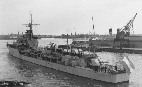
D805 Piet Hein, ex HMS Serapis, WW2 S class destroyer

So, I walked the dogs, thought a little and made a decision.

We start over. Completely.

D805 part III.

I keep on bumping into small irritators and I really must bury these gremlins.
- I don’t like the hull shape: it’s just not right bow and stern. Too flat. I’d say it’s 85% right. Not good enough, especially as I really love those sweeping lines.
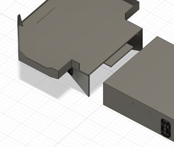
- I don’t like the deckhouses: I’m going to do those in resin. So will have to wrestle detail (simple) vs flat surfaces (hard).
- And the bridge … requires a different cut to make it printable. A mix of surfaces, details and space.

And even before I start the work, I feel renewed energy. So I made the right decision. Sometimes you really must stop repairing and take a few steps back.

Oh boy.

But I’m smiling.
Wow, that’s what we called a ‘RE-DO’! But the right decision, Marco. You would have looked at it every time ……..
Regards, Peter
 
Funny thing that once you take a step back, you suddenly see all kinds of little mistakes and forgotten items. I guess that was also why I somehow felt distanced from the ongoing design. In the meantime I spent a good afternoon creating a new bridge and deckhouse and saw that I made a really strange cut to make it printable. There is a perfect spot where the side of the deckhouse slopes inward. Even if I miss "a bit", that will always fit. No clue why I missed that at first go.

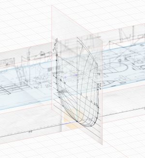
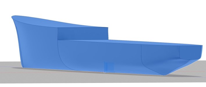
I started with the new hull this afternoon as well and saw where I went wrong. The drawings are a bit ... let's say a mixed bunch of a top view by one and a frontal view by someone else. My plan is to follow ONE logic and create virtual ribs that I will then virtually plank. So the horizontals will be a result of the verticals. A quick sketch showed me a much better slope in the bow section.

Onward!

Screenshot 2025-03-03 at 14.25.45.jpg
 
I started with the new hull this afternoon as well and saw where I went wrong. The drawings are a bit ... let's say a mixed bunch of a top view by one and a frontal view by someone else. My plan is to follow ONE logic and create virtual ribs that I will then virtually plank. So the horizontals will be a result of the verticals. A quick sketch showed me a much better slope in the bow section.
Back in the days we used a function surface analysis, where we could check curvature, tangency, surface radii and a myriad of other complex stuff I forgot the meaning of. I think I asked @Peter Voogt a while ago on his Balder build log, but I'm not sure if Fusion has that particular capability. To me that function was very helpful to ensure the quality of the generated surfaces.
 
Thanks for the supporting thought!

There actually is a virtual tool in Fusion. I’m sure engineers will have a go with that. And I use a so called “comb” when I think an edge ends too abruptly.

But my issue is rather more aesthetic. I simply didn’t like the (lack of) curvature in the bow section. These destroyers had a so called “Atlantic bow”, while my ended up having almost no slope.
 
But my issue is rather more aesthetic. I simply didn’t like the (lack of) curvature in the bow section. These destroyers had a so called “Atlantic bow”, while my ended up having almost no slope.
The abive raises some questions/remarks:
1. So at least two different versions were defined: an "Atlantic" bow and a "normal" bow?
2. If @1 is correct, I assume there would have to have been two sets of drawing, one for each bow version.
3. Do the drawings you have at hand lack the required bow definition or are the surfaces you generated too strongly "attached" to the rest of the hull definition?

Unfortunately your surface definitions are the root of all evil or the route to succes. Imperfections in the surfaces will stick out like a sore thumb.

I must admit that I'm very impressed by your perseverance; throwing out quite some work and start all over again; kudos!
 
I'm sure that there are more knowledgeable people in the forum, but:
1) the "Atlantic bow" had more flare and was common for the Royal Navy (and the German navy at that). It helped with the rough seas and lessen water over decks. But that went at cost of (some) speed and/or fuel cost. When you look at e.g. the US Navy destroyers, the had more "sharp" bows, helping with speed and fuel consumption. That was necessary, as they operated in the Pacific.
2) No, that's me not being perfectly clear: there is one drawing of this specific ship, but the top view differs from the station view. The top view creates a slimmer ship, whilst the actual curvature can be found in the station views. So I have to first draw these and create my own top view. I need that top view in at least two layers to create so called 'guides" that "push" my loft along a specific path (iso along what Fusion thinks is the shortest way).
3) See point two. I think that the creator, who made the plans in 1984, did not think in 3D. So each view looks correct, but does not necessarily match one on one with the other views. And when I look at images, I see differences as well.

And I agree that the hull line must be correct. If that is off, the whole ship will be offish. And starting over is actually easier than trying to repair. And if you look back, you'll find out this is actually version 3. The first one was in 1/96 scale and well on its way to the finishing line, when mistakes in the printing (my lessons learned) resulted in sticky resin goo dripping all over the model.

When you look at the image - D805 setting sail for "the East" - , you will see the typical curved line of the flared bow I am trying to create.

Screenshot 2024-11-25 at 15.42.23.jpeg
 
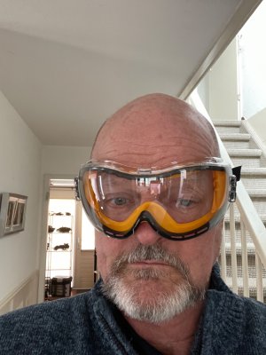
Things are slowing down again ... I had new lenses implanted last Thursday and although all is fine, it's not yet at a level that I can work in Fusion or worse, in my work shed. But even after a few days things are picking up. It will probably take a week or two before my sight is up to par and I'll have to wear goggles when I'm in the works shed for at least a month. Oh well. Life without glasses is great.

It gives me some time to think about the hull lines.

Luckily I don't have to sleep with those goggles on ROTF:cool:

IMG_6110.jpeg
 
Things are slowing down again ... I had new lenses implanted last Thursday and although all is fine, it's not yet at a level that I can work in Fusion or worse, in my work shed. But even after a few days things are picking up. It will probably take a week or two before my sight is up to par and I'll have to wear goggles when I'm in the works shed for at least a month. Oh well. Life without glasses is great.

It gives me some time to think about the hull lines.

Luckily I don't have to sleep with those goggles on ROTF:cool:

View attachment 507405
LOL ROTFROTFROTFROTFROTFROTF
 
Things are slowing down again ... I had new lenses implanted last Thursday and although all is fine, it's not yet at a level that I can work in Fusion or worse, in my work shed. But even after a few days things are picking up. It will probably take a week or two before my sight is up to par and I'll have to wear goggles when I'm in the works shed for at least a month. Oh well. Life without glasses is great.

It gives me some time to think about the hull lines.

Luckily I don't have to sleep with those goggles on ROTF:cool:

View attachment 507405
Hopefully the recovery goes quick and well, Marco.
Regards, Peter
 
Hi Marco.
I have been away for a week or so,(Cheltenham), and am just catching up. Wow! I hope the eye operation has gone well and you are back in harness soon.

Best of luck Jack.
 
It's quite interesting to see that with some time away from the drawings, you realise there are several inconsistencies in the originals. I had already noticed (but forgotten, so I lost another few hours on redoing what could've been done correctly first time around) that the three dimensions are not in the same scale. But that hull line that was a tad off kept nagging, so I dug up some more information. And suddenly I saw that the general station view with all the ribs was not only in a different scale (I think somewhere around 1/85), but over time was also not correct length x width. It must be a result of copying, then compressing, then cutting up to paste all together again and print at 1/100 (about).

A lot of text to explain that the sweep of the hull did not follow the horizontal logic. Truly debilitating is the fact that over time some lines were not straight anymore. Hasty reprints over some 45 years. Oh well.

I did a lot measuring and trying to bring things together in three dimensions, but wasn't able to get that station view correct. Either the width was correct and the waterline level was off, or I got that correct and the width jumped. So I stepped away from that and decided to call two dimension correct and adapt the ribs to fit as a third dimension. I can still use the general line of each rib, but will have to tinker a little to make it fit. In the end there is a certain logic and beauty in the overall hull line, so I'm sure I'll get that right.

You probably wouldn't notice this as much when building the hull from wood. Cutting each rib from paper, tracing on and then sawing from wood, etc. would hide the few millimeters here and there. But that's not how Fusion works. All three dimensions must connect at specific points, otherwise the loft is not possible. Or you are unable to use guides to push and pull the machine created best effort loft to the required true shape.

The good thing is I'm on my way again, am learning and now really understand the hull in detail. And with all the lessons learned I can move forward swiftly.


Screenshot 2025-03-19 at 16.06.48.jpg
 
And half an hour later ... the stern is taking shape. And yes, I know the bow section is the hardest. But the logic works!
View attachment 508439
It’s good to read that you found what was wrong and found your solution, Marco. Each time a bit offscale and the fault increases. And most of the copiers are not making a 100% 1:1 copy. This has been established empirically several times in our CSI office.
Regards, Peter
 
In the end it will be on my shelf, bookcase or whatever and I have to be the one to be happy with it :) . And I am aware of the pitfall of forever ongoing changes, as I come from an industry that required a solid "stop engineering, it is sufficient". We had a good measuring stick: acceptance by customer.

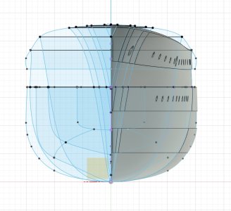
The new hull shape is much better and I will go with it for further detailing. The curves are as I want them to be. On with the next phase: plating, portholes and such. Lots of work, lots of fun.
Screenshot 2025-03-20 at 11.42.15.jpg
 
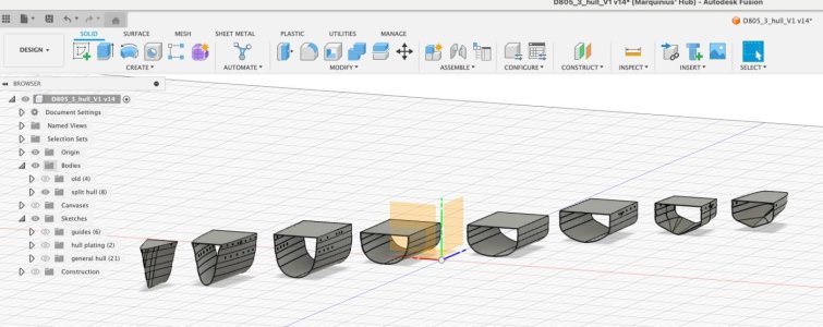
Working with so many lines and faces requires some organisation. But I guess it is like when you are fully engaged on your workbench and tools start getting scattered all over the top. So I will have to clean up a little after this phase. Group stuff and clean away anything that was only required for lofting (but NOT delete as that would have immediate effect on the lofted body).

But it's a fun picture ...

Screenshot 2025-03-20 at 15.04.50.jpg
 
Back
Top