DE 7 PROVINCIËN (1665) 1:50

I have chosen for building this ship as my father left me the book "De 7 Provinciën" by G.C. Dik. A book that comes with a set of plans (1:77). Years later I decided to actually build this model.
I wanted the model to be a bit larger than it would be on a scale of 1:77, envisioning a completed model in our living room. We have double doors entering this room with on both sides about 1,6 / 1,7 meter free wall, What a sight it would be to have one or even better to have a model on each side of the entrance of our living room. A fine scale to build this model would be about 1:48-1:50 making it a model of roughly 1.30 meter over all.
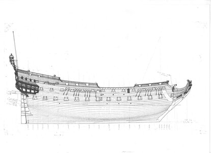
More info on this ship/model was searched for and found amongst other things on the website of the now deceased Otte Blom, who made an elaborate study of this ship and his drawings/plans can be found on internet. I looked around on several forums and found a building log by Dražen Carić, whose method appealed to me and for a first build (it has been over 40 years since I built a model) it appeared to me to be a good role model to get me started.
In the meantime I have collected several books to get deeper into the matter of 17th/18th century ship building and rigging. My latest and much appreciated acquisition "The Art of Ship Modeling" by Bernard Frolich (ancre.fr).

.. to be continued ..
If you look at a newer kit company called Kolderstock, a 1/77 scale kit of der Zeven Provencien is available. I have heard that it is an excellent kit!

Bill
 
Thank you all for the nice comments and likes, much appreciated.

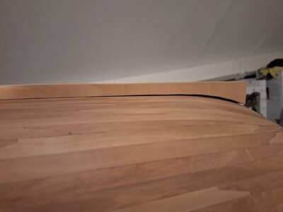
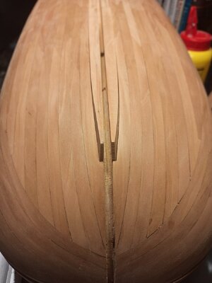
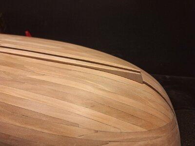
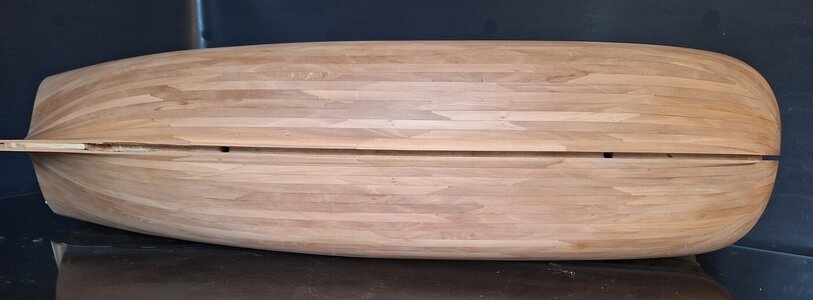
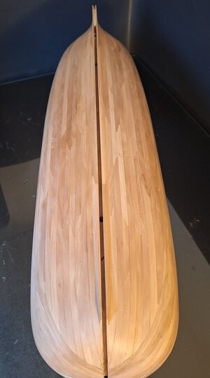
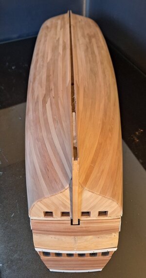
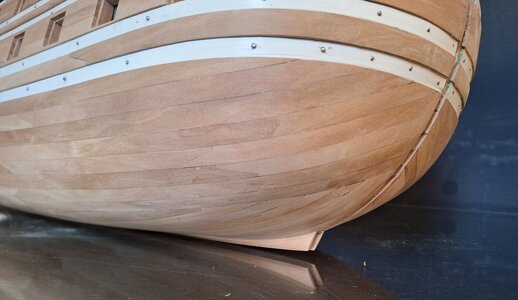
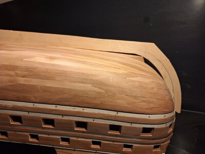
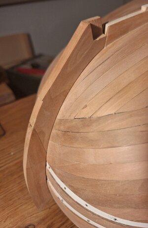
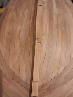
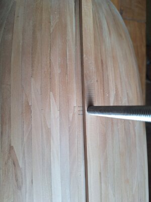
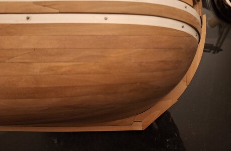
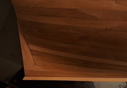
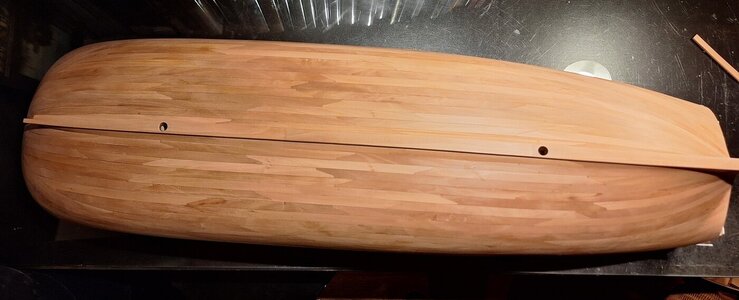
Finally the last row of planks, the garboard strake, has been installed.

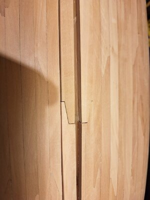
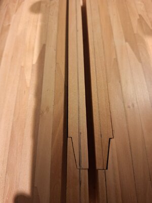
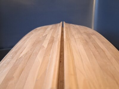
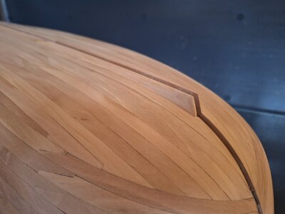
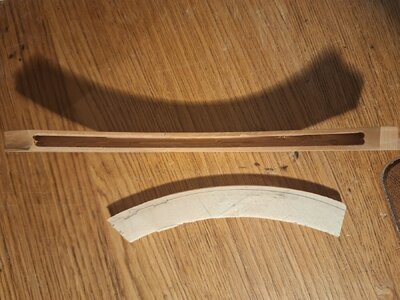
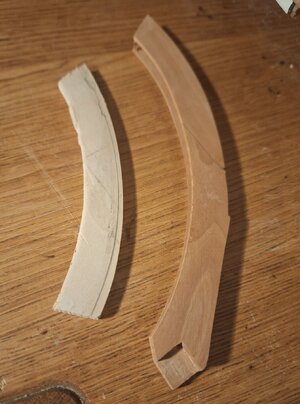
The front planks were shaped out of 2 pieces of wood, not bent, but shaped to fit the curvature of the hull and tapered towards the front.

20240203_180520_resized.jpg

20240204_173017_resized.jpg

20240204_173030_resized.jpg

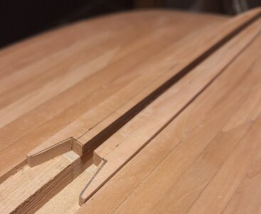
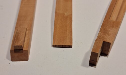
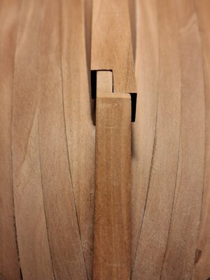
And of course provided with scarphed joints.

20240204_173909_resized.jpg

20240204_193429_resized.jpg

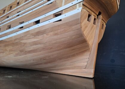
The planks used are somewhat thicker than the hull planking to realize the slope of the garboard strake into the keel. the pencil line is the line representing the total width of the keel bar. The slope of the garboard strake is realized by means of tapering the corner towards the pencil line.

20240207_195341_resized.jpg

20240218_144110_resized.jpg

20240218_143641_resized.jpg

Total view:

20240218_143501_resized.jpg

20240218_143950_resized.jpg

20240218_144015_resized.jpg

20240218_143221_resized.jpg

20240218_143349_resized.jpg
 
Thank you all for the nice comments and likes, much appreciated.

Finally the last row of planks, the garboard strake, has been installed.

The front planks were shaped out of 2 pieces of wood, not bent, but shaped to fit the curvature of the hull and tapered towards the front.

View attachment 428758

View attachment 428759

View attachment 428760

And of course provided with scarphed joints.

View attachment 428761

View attachment 428762

The planks used are somewhat thicker than the hull planking to realize the slope of the garboard strake into the keel. the pencil line is the line representing the total width of the keel bar. The slope of the garboard strake is realized by means of tapering the corner towards the pencil line.

View attachment 428763

View attachment 428770

View attachment 428767

Total view:

View attachment 428766

View attachment 428768

View attachment 428769

View attachment 428764

View attachment 428765
That looks very nice, Herman.
Regards, Peter
 
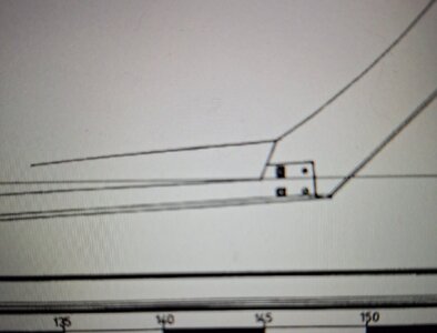
Okay, Blom. Yes he ends there a bit strange.
It might be a bit strange but you see something similar on the "Hohenzollern" model of the Dutch twodecker.

post-1930-0-17922900-1487440532.jpg

It maybe looks now a bit too pronounced (more protruding as per the drawings of O.Blom than as per the Hohenzollern model) but I think it will look more natural as soon as the keel and bow are installed.
 
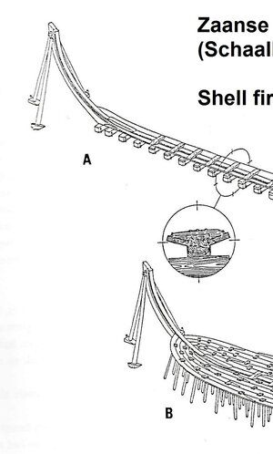
Indeed there are drawings they show it your way, even more extreme. The first 2 rows of planking following this way to. This is a drawing of the HZ I believe, not sure.

010.jpg

I followed the line plan of the HZ in combination with the drawings of Hoving and there is the "zandstrook" in a more flowing way to the "voorsteven"

schaalbouwxx.jpg

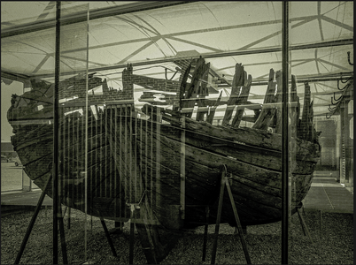
The Pinas Samuel in Den Helder is the wreckage. Looks like the drawings of Hoving. Maybe someone got a better picture of the front.
Naamloos.png

We will see when the "stevens" and the keel is installed on your ship. You used the drawing of Blom and in that case you keep to that. Nice work.
 
Thank you all for the nice comments and likes, much appreciated.

Finally the last row of planks, the garboard strake, has been installed.

The front planks were shaped out of 2 pieces of wood, not bent, but shaped to fit the curvature of the hull and tapered towards the front.

View attachment 428758

View attachment 428759

View attachment 428760

And of course provided with scarphed joints.

View attachment 428761

View attachment 428762

The planks used are somewhat thicker than the hull planking to realize the slope of the garboard strake into the keel. the pencil line is the line representing the total width of the keel bar. The slope of the garboard strake is realized by means of tapering the corner towards the pencil line.

View attachment 428763

View attachment 428770

View attachment 428767

Total view:

View attachment 428766

View attachment 428768

View attachment 428769

View attachment 428764

View attachment 428765
Good morning Herman. Way to go. You owned this. Cheers Grant
 
The Pinas Samuel in Den Helder is the wreckage. Looks like the drawings of Hoving. Maybe someone got a better picture of the front.
View attachment 429009

We will see when the "stevens" and the keel is installed on your ship. You used the drawing of Blom and in that case you keep to that. Nice work.
If it is interesting for your, I took some pictures during my holiday last year.
 
I have been working on the keel and the stem post that must match the front part of the keel.
First I inserted the plywood into the slot in the hull and marked it with a pencil to get the correct form for the stempost.

20240220_194134_resized.jpg

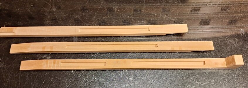
The three parts for the keel were made and provided with slots.

20240220_194312_resized.jpg

The aft, middle and front part of the keel:

20240305_195853_resized.jpg

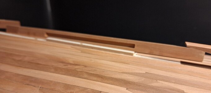
The plywood was inserted into the hull and reduced to protrude just a little to fit into the sluts of the keel.

20240221_194139_resized.jpg

Same procedure for the stempost.

20240302_195936_resized.jpg

20240302_200010_resized.jpg

20240302_200119_resized.jpg

Now matching the stempost and the keel

20240302_200244_resized.jpg

20240305_200030_resized.jpg

Two holes were made in the keel for the stands.

20240303_163133_resized.jpg

And the parts of the keel were glued to the model.

20240308_200436_resized.jpg

20240308_200508_resized.jpg

20240308_195934_resized.jpg

The stempost has not yet been glued to the model. I keep the stempost removable as long as I am working on different parts of the bow.
 
Last edited:
Back
Top