DocBlake's HMS Blandford Cross Section Build - 1/32 Scale - [COMPLETED BUILD]

I spent the last couple of days prepping and installing the sheer rail with it's supports. Again, made of pear, stained black. I don't have a mill, so to make assembly easier and more sturdy, I beefed up the sheer rail supports a bit compared to Mike's plans. This is OK, because the supports aren't even shown on the NMM plans or some contemporary models, but are on others. In any case, I think the rails turned out OK. The gun ports are a little taller than they would be a little further forward on the ship. This is due to the rising rails moving aft, and is shown on the plans.

There is a little groove plowed into the waist rail as a decorative trim (see arrow)View attachment 112155View attachment 112156View attachment 112157View attachment 112158. I'm considering painting this. Gold, or blue perhaps. Any thoughts?
I think gold would be too 'glaring' bright at this scale, as would light blue, and dark blue would be lost. Frankly, I would leave it as it is!

Ted
 
I think you're right, Ted. I fit a little strip of holly in that groove to see how it would look and I nearly had to put sunglasses on to cut the glare!! :D I tested some blue on a scrap of the rail I had and it did get "lost" there. Nothing might be best in that groove.
 
Dave, a question about the bolts in the frames, when you drilled the holes for the bolts, did you drill all the way through the entire frame so that the bolt appears/seen from both sides? , if I use brass thread 8mm instead of black wooden nails, will it be totally wrong ?, I will start making bolts in all frames now and I want it to be as correct as possible, I will try to mount the bolts as you have done. Thanks.-
.
 
Hi Knut!
I think you mean 0.8mm for the brass! That's 1 scale inch in diameter and about right. Since there is very little bevel to the frames after fairing, you could drill all the way through and be OK. I prefer to drill a separate hole on each side so they can be aligned best with the futtock joints. It's your call. My way is more work!
 
Thanks Dave, I think I go for 8mm brass bolts for the frames and do as you say you make the holes one side at a time.
Then it will also be much easier to get all the bolts placed correctly and evenly on both sides.
I'm still struggling to make wooden nails because of the wrong / bad draw plate, so I want to make all the bolts of brass.
Will also have to get another draw plate, I will not give up.
.
 
Knut: You really don't need a drawplate!! I assume you can purchase common toothpicks where you are. What I do is break off the ends of toothpicks and soak them in a bath of black dye overnight and then let them dry out. Drill your appropriate sized holes. Depending on what size drill you use to drill the simulated bolts, the toothpick tips fill the holes because they are tapered. Dip the tip of the toothpick in CA glue and push it into the hole and let dry. Snip off the toothpicks and sand. If the toothpicks sit in the dye long enough, they will be black throughout, with no "white" center. Works like a charm!
 
Thanks for the tip Dave, I think you talked about this technique once in a while, I'll do and try with toothpicks you talk about, today I measured and marked all the frames, now ready to drill all the holes.
Today I buy toothpicks and do as you tell.
The bolts you made in the keel, are they thicker than the bolts in the frames ?.
I really appreciate your help and your good building log, where I learn a lot just from what the pictures show.
Greeting-
 
I believe the bolts in the keel are thicker, Knut. I don't remember how much!

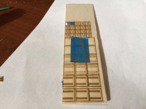
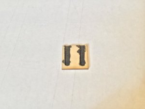
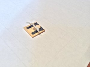
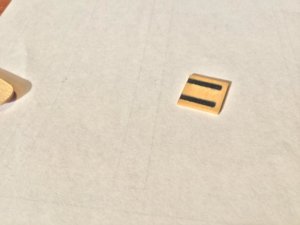
I'm beginning to work on the final details on the exterior of the model. There are 6 sweep port covers and one ballast port cover per side. When Mike designed the model, the idea was to keep the framing simple, so understandably the sweep ports and ballast ports were not framed in. In the original ship, the port covers would have sat flush with the outboard planking. In the model, they will be glued onto the planking. The plans call for 1/16" stock for these parts. I'm using boxwood so I thought I could go thinner - I used 1/32" thick boxwood. A soft wood like basswood wouldn't hold up at 1/32". I also need a way to add those horseshoe shaped hinges to the sweep port lids. I talked to my good friend Mike Shanks, and he offered to cut the parts out of 1/32' boxwood and etch the hinges for me! Then it was a simple matter to paint the hinges. Mike left masking tape on the good surface of the boxwood so there is no laser scorch on the good face, and it masks the wood where the hinges are, so all I had to do was slop on the paint and let it dry. Once dry, peel off the masking tape, and nice clean hinges result. Here are some pictures. Thanks, Mike!laser1.jpglaser2.jpglaser3.jpglaser4.jpglaser5.jpglaser6.jpg
 
Thanks for the tip Dave, question - the little hatches you show in the pictures, cut and fold them into the hull like the cannon hatches ?.
In the drawings in the book about Blandford, it looks like all the hatches go in one with hull / planking.
 
I believe the bolts in the keel are thicker, Knut. I don't remember how much!

I'm beginning to work on the final details on the exterior of the model. There are 6 sweep port covers and one ballast port cover per side. When Mike designed the model, the idea was to keep the framing simple, so understandably the sweep ports and ballast ports were not framed in. In the original ship, the port covers would have sat flush with the outboard planking. In the model, they will be glued onto the planking. The plans call for 1/16" stock for these parts. I'm using boxwood so I thought I could go thinner - I used 1/32" thick boxwood. A soft wood like basswood wouldn't hold up at 1/32". I also need a way to add those horseshoe shaped hinges to the sweep port lids. I talked to my good friend Mike Shanks, and he offered to cut the parts out of 1/32' boxwood and etch the hinges for me! Then it was a simple matter to paint the hinges. Mike left masking tape on the good surface of the boxwood so there is no laser scorch on the good face, and it masks the wood where the hinges are, so all I had to do was slop on the paint and let it dry. Once dry, peel off the masking tape, and nice clean hinges result. Here are some pictures. Thanks, Mike!View attachment 112971View attachment 112972View attachment 112973View attachment 112974View attachment 112975View attachment 112976
An interesting technique, and I like the idea of the masking tape to stop scorching! I'm wondering whether it might be worth putting a coat of sanding sealer on the timber before applying the black paint - it might stop the very slight bleed of paint that is showing in some pictures?
Ted
 
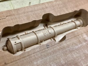
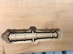
What's all this about?? Is it possible? How was this made? :cool:
Just WOW, Mike! obviously, if you made it, - it is possible. How was this made? My big guess would be CNC given the fact it is a block of wood or? For wood it is very smooth and even grain, then it kinda plastic??? But honestly - WOW! this cannon looks amazing detail. I am wondering what on the opposite side (the dark side of the moon)! I can not wait for you to reveal the secret.
 
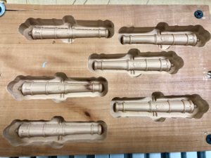
How about 6 of them? They are indeed CNC machined, 2-sided, full 3D, in Swiss Pear. It took me many, many hours to get them just right. Let's wait and see what Doc does with them after he returns from vacation.

IMG_1737.JPG

Here is the back side of the first one including it's profile cutout.
IMG_1738.JPG
 
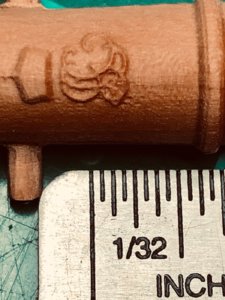
The King George I monograph was especially difficult. I traced it from a piece of art work and then rendered it in 3D with Vectric Aspire. It is carved with a 0.5mm tapered bit and stands 0.015" proud of the cannon surface. Enjoy.

IMG_1741.JPG
 
Back
Top