H.M.S. Victory by Caldercraft - Build Log

An hour here, an hour there!

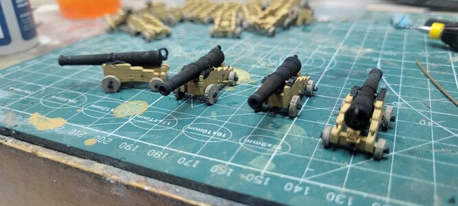
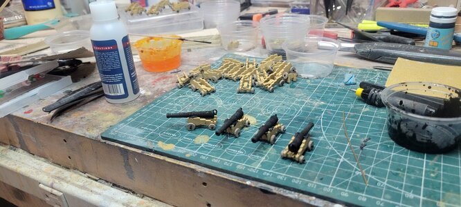
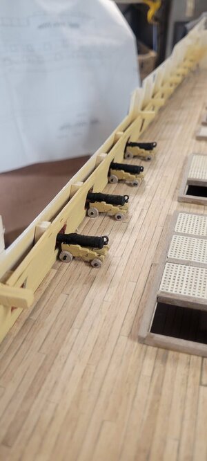
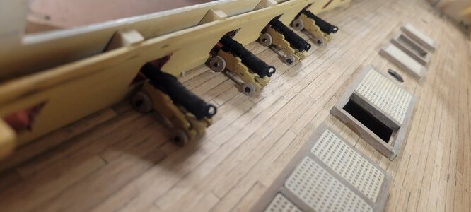
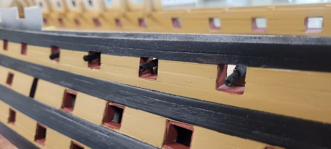
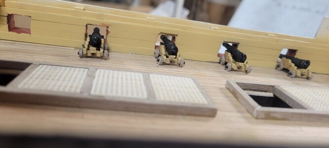
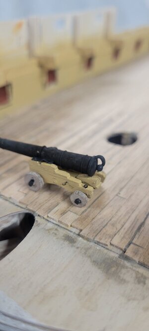
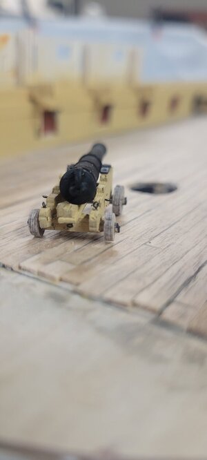
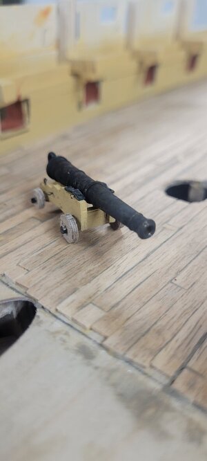
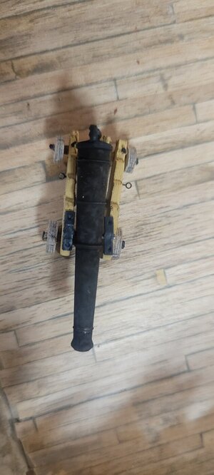
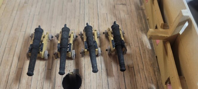
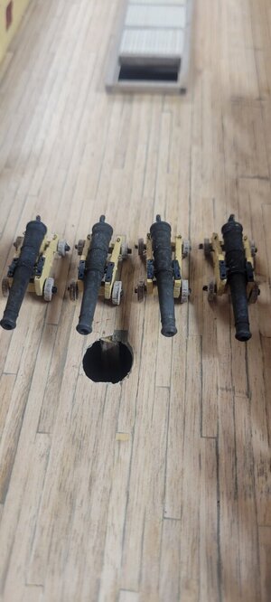
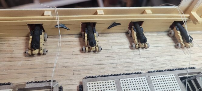
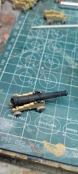
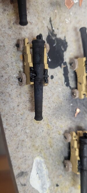
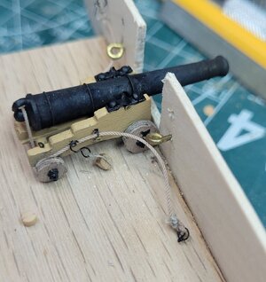
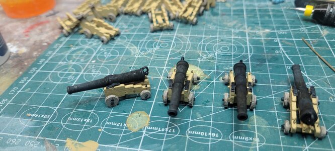
I blackened the cannons and all of the various bits that are attached to the cannon bases. It's a love hate result.
I think you have to polish the finished result with a clean cloth, but doing so will rub off some of the black, which will require you to dip them again.

Now pictures, as always will enhance the reality these are miniatures (built by a rookie) and will enhance my flaws.
But from farther away, they look fine.

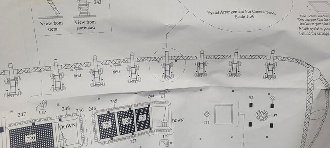
Drilling the holes for the various eyelets is tough. .5mm bits are very thin and if you are not careful, you will break them, I think I started with 5 or 6 of them and they are all gone!!!

Also, the directions require a .7mm hole for the bolts that hold the trunnions in place. It was almost impossible to do this with any precision.
I have a drill press and suppose I could have rigged that up and secured each cannon base in place....I didn't bother.

My thinking is that once painted, they blend in. Once I am done creating the 10 showcase cannons I might consider cutting the heads off the pins that were meant to hold the trunnions in place and just glue them in the holes for the aesthetics of it all!

I did have to touch up the cannon breeches because the blackening agent doesn't work on CA glue, but I knew that was going to happen.
To be honest, for those that want to go with a paint option, the dried result looks great and I would guess that painting the cannons and ensuring they are drip free will look just fine!

The forward eyelets are there to hold a ring that the breeching rope runs through as it goes from the bulkhead wall to the cannon, around the back and back through a ring on the other side on its way to the other side and bulkhead. I have a way to make rings, just not sure yet what size wire to use. The wire I used to make the breeching loops is just too thick. I think I have some very thin brass wire. I'll keep you posted.

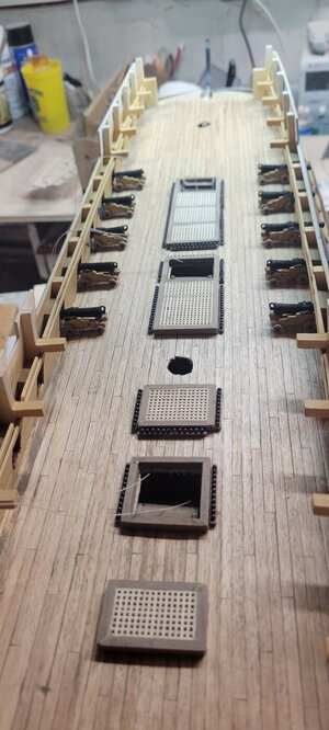
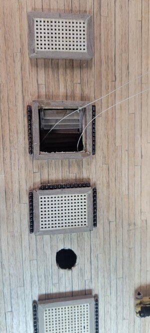
I also installed the 3 crooked ladders I made in addition to adding the lower stanchions for the rope railings. That was a bit tough to do because of the angle of the stairs in relation to the upright angle needed for the stanchion. Also, trying to guesstimate how much thread to leave for the finished railings was tough. Hopefully I guessed right!

Oh yes, the manual asks for .25mm thread for the rope railings. Once blackened or even painted, there is NO WAY to get a thread that thick through the stanchion holes. That is where I broke my last .25mm drill trying. So I am using the .1mm thread....at least for these railings that are a but lower.

Perhaps I will see what I can do to the stanchions for the next deck BEFORE I remove them from the sprue.
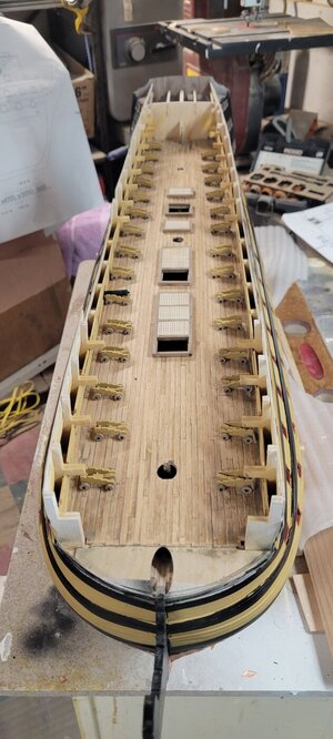
20240629_162826.jpg

20240630_182938.jpg

20240630_182944.jpg

20240630_182947.jpg

20240630_183036.jpg

20240630_183047.jpg

20240630_183100.jpg

20240630_183116.jpg

20240701_114737.jpg

20240701_114745.jpg

20240701_114755.jpg

20240701_114807.jpg

20240701_114830.jpg

20240701_114848.jpg

20240709_144555.jpg

20240709_144601.jpg

20240709_144605.jpg

20240709_144608.jpg

20240709_144613.jpg
 
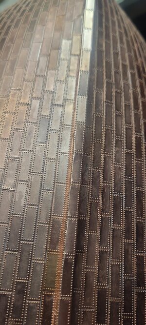
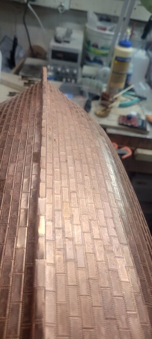
While doing that, I wanted to finish the copper plating on the keel base.
Because of the width of the wooden keel base along with the copper plating on each side, it is just a bit thinner than a copper plate.
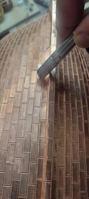
Had I installed the bottom plates FIRST, I could have easily used my PE bender to bend just a bit on each side.

But once the side plates are installed, there was no way for me to get that thin a piece of the plate under the bender.
So I installed the plates on the keel and once dried, I used the burled end of one of my exacto knives to roll the ends down. I popped a few and had to redo them, but if you are careful you can get them to square off. This part of the boat is buried under any stand you'll select and the copper plates work together to create a pretty cohesive look that hide any imperfections of installation.

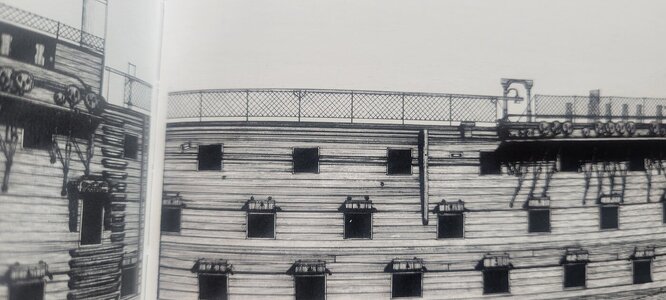
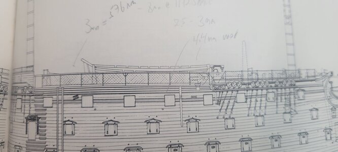
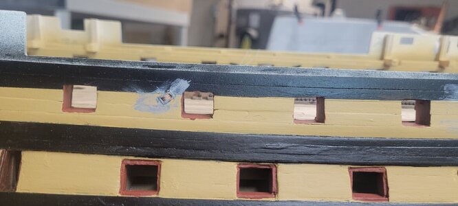
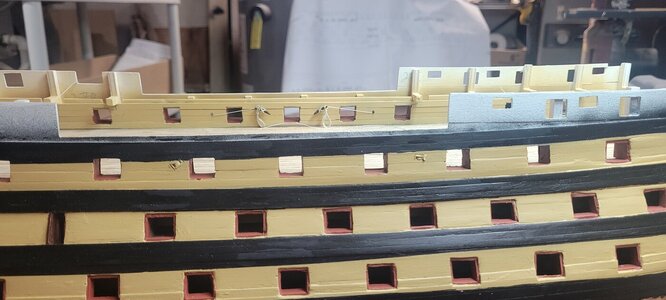
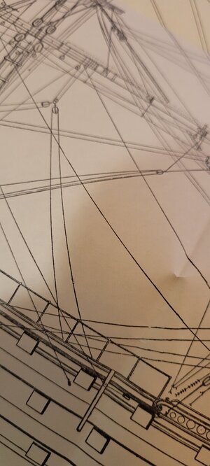
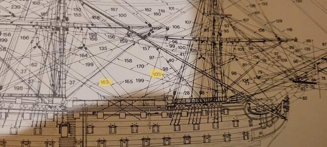
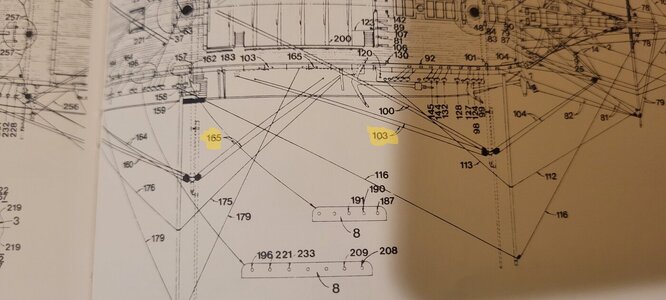
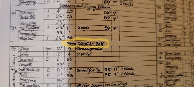
On the books I have, there are 4 locations on the side hull for a set of single sheaves and double sheaves. I believe they hold running rigging lines for the some of the main course sails.

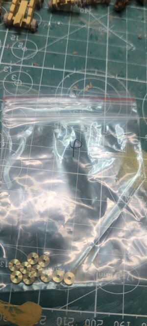
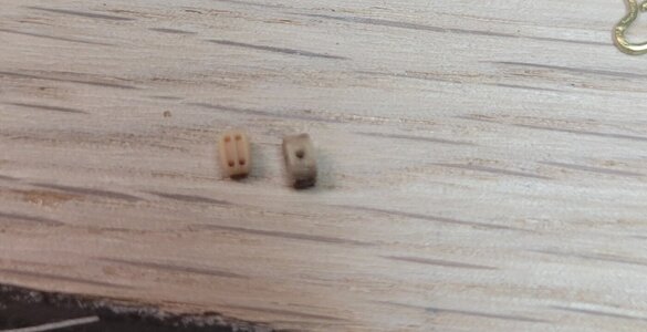
Using some math, I think that 4mm sheaves would do the trick. I bought some 4mm brass and wooden sheaves for a choice.
I built little boxes for each and the double wooden sheaves are a bit thinner and I like them better than the double brass.

However, I used the brass sheaves for the single set up.

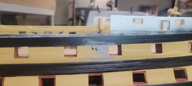
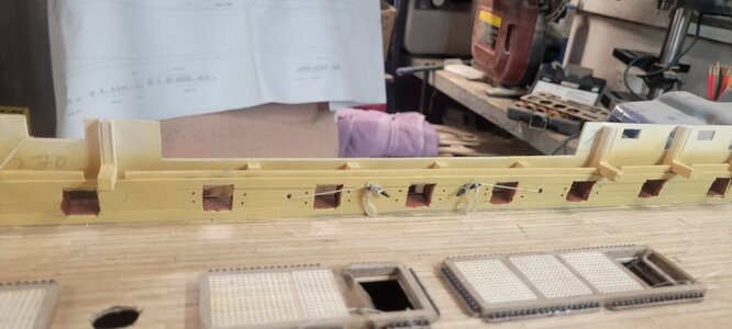
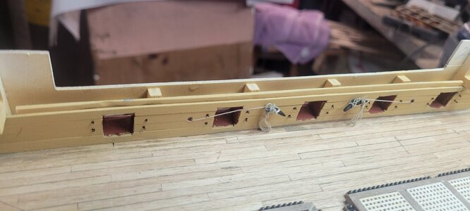
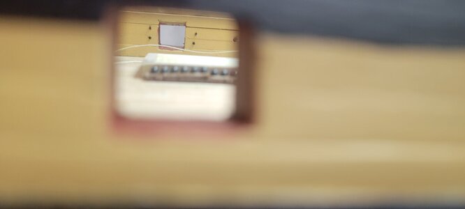
Once done, I drilled out the locations where I think they should be and installed them. They are ok and I will have to do some work to clean them out a bit.

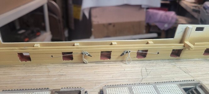
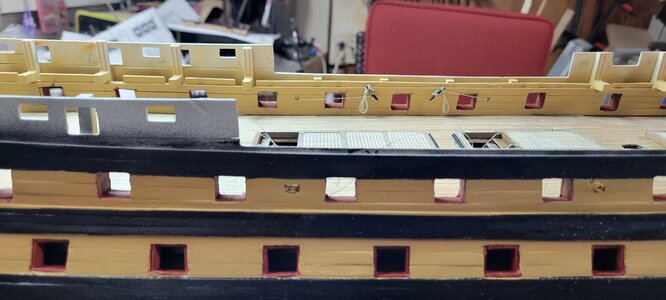
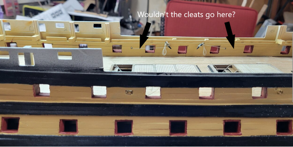
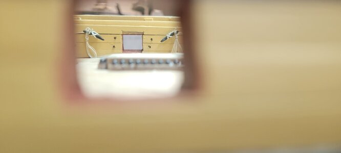
Now, there should be identical sheaves on the inside bulkhead walls, but I opted to just drill a hole. Once done, I created some rope shanks for the cleats that are installed on the upper deck. They are a but too long, but I think they add a little realism that you will barely see!!!

These sheets might be in the way of the cannons and I tried to find a pic of how they would actually be run, but as the current ship doesn't have the masts installed those sheets are no longer in place.

Thanks!

20240711_120322.jpg

20240711_120327.jpg

20240711_123211.jpg

20240711_123536.jpg

20240711_123638.jpg

20240711_123704.jpg

20240711_140633.jpg

20240711_140636.jpg

20240711_155644.jpg

20240711_155650.jpg

20240711_155712.jpg
 
While doing that, I wanted to finish the copper plating on the keel base.

Because of the width of the wooden keel base along with the copper plating on each side, it is just a bit thinner than a copper plate.
Had I installed the bottom plates FIRST, I could have easily used my PE bender to bend just a bit on each side.

But once the side plates are installed, there was no way for me to get that thin a piece of the plate under the bender.
So I installed the plates on the keel and once dried, I used the burled end of one of my exacto knives to roll the ends down. I popped a few and had to redo them, but if you are careful you can get them to square off. This part of the boat is buried under any stand you'll select and the copper plates work together to create a pretty cohesive look that hide any imperfections of installation.

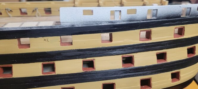
On the books I have, there are 4 locations on the side hull for a set of single sheaves and double sheaves. I believe they hold running rigging lines for the some of the main course sails.

Using some math, I think that 4mm sheaves would do the trick. I bought some 4mm brass and wooden sheaves for a choice.
I built little boxes for each and the double wooden sheaves are a bit thinner and I like them better than the double brass.

However, I used the brass sheaves for the single set up.

Once done, I drilled out the locations where I think they should be and installed them. They are ok and I will have to do some work to clean them out a bit.

Now, there should be identical sheaves on the inside bulkhead walls, but I opted to just drill a hole. Once done, I created some rope shanks for the cleats that are installed on the upper deck. They are a but too long, but I think they add a little realism that you will barely see!!!

These sheets might be in the way of the cannons and I tried to find a pic of how they would actually be run, but as the current ship doesn't have the masts installed those sheets are no longer in place.

Thanks!

View attachment 458670

View attachment 458671

View attachment 458672

View attachment 458673

View attachment 458674

View attachment 458675

View attachment 458676

View attachment 458677

View attachment 458678

View attachment 458679

View attachment 458680
They actually had lines running across the gun ports to belay on the cleats? Doesn't make sense to me.
 
They actually had lines running across the gun ports to belay on the cleats? Doesn't make sense to me.
I am not 100% sure of this, pics of the running rigging show lines (which look to come from the clews of the lower main courses) down into the sheaves on the hull side. Then there are other pics of the interior walls on the upper deck with identical sheaves. These seem to be very close to the cleats and I see no other way to secure those lines other than across open gun ports.

However, most running rigging would be on the top decks of a ship, not sure why any running rigging would be on a lower deck forcing someone to have to run down for adjustments or to be assigned to wait there while sailing? So it is very possible I have misunderstood the role of those sheaves!!!!
 
Assuming the sheaves are in the correct locations...
View attachment 459181
It would be a good idea to seek out photos of the Victory for these locations to confirm where things go. Can any of our Victory builders please provide that evidence?
Hi Kurt....I was doing other work on computer when I saw your post and had to run downstairs to check!!!

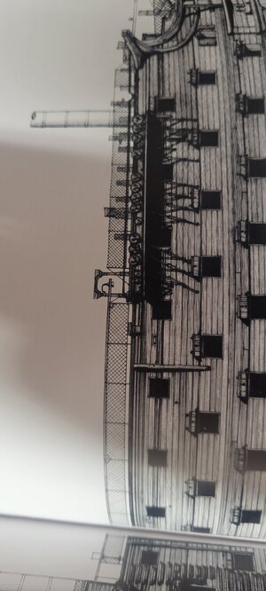
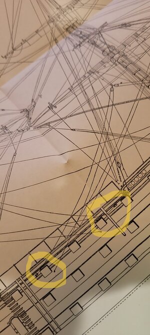
So your thoughts make complete sense. But the plans call for these cleats (just looking at the most forward cleat) to be mounted between the 5th and 6th gun port, but the sheave is between the 4th and 5th window.

There is also an iso view of the interior showing the location of the cleats....

But I think your positioning makes more sense.

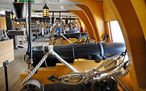
It's hard to find current pictures of this deck, there is so much 'museum clutter' for tours and to provide as much information as possible that some of the this type of detail is lost.

While I cant change the sheaves, I can certainly alter the interior if needed!!!!!

20240714_124915.jpg

20240714_125031.jpg

20240714_125117.jpg

20240714_125125.jpg
 
Hi Kurt....I was doing other work on computer when I saw your post and had to run downstairs to check!!!

So your thoughts make complete sense. But the plans call for these cleats (just looking at the most forward cleat) to be mounted between the 5th and 6th gun port, but the sheave is between the 4th and 5th window.

There is also an iso view of the interior showing the location of the cleats....

But I think your positioning makes more sense.

It's hard to find current pictures of this deck, there is so much 'museum clutter' for tours and to provide as much information as possible that some of the this type of detail is lost.

While I cant change the sheaves, I can certainly alter the interior if needed!!!!!

View attachment 459182

View attachment 459183

View attachment 459184

View attachment 459185
When something doesn't make sense, don't trust the model plans without verifying the feature using other sources of information. Plan are OFTEN wrong,(and John McKay is occasionally also). Those sheaves appear to be located in places for the fore course brace lines and main tack lines. Seek out a rigging diagram and verify what the lines for these sheaves do and where they are belayed. It should be easy, the ship still exists!
 
Last edited:
While doing that, I wanted to finish the copper plating on the keel base.

Because of the width of the wooden keel base along with the copper plating on each side, it is just a bit thinner than a copper plate.
Had I installed the bottom plates FIRST, I could have easily used my PE bender to bend just a bit on each side.

But once the side plates are installed, there was no way for me to get that thin a piece of the plate under the bender.
So I installed the plates on the keel and once dried, I used the burled end of one of my exacto knives to roll the ends down. I popped a few and had to redo them, but if you are careful you can get them to square off. This part of the boat is buried under any stand you'll select and the copper plates work together to create a pretty cohesive look that hide any imperfections of installation.

On the books I have, there are 4 locations on the side hull for a set of single sheaves and double sheaves. I believe they hold running rigging lines for the some of the main course sails.

Using some math, I think that 4mm sheaves would do the trick. I bought some 4mm brass and wooden sheaves for a choice.
I built little boxes for each and the double wooden sheaves are a bit thinner and I like them better than the double brass.

However, I used the brass sheaves for the single set up.

Once done, I drilled out the locations where I think they should be and installed them. They are ok and I will have to do some work to clean them out a bit.

Now, there should be identical sheaves on the inside bulkhead walls, but I opted to just drill a hole. Once done, I created some rope shanks for the cleats that are installed on the upper deck. They are a but too long, but I think they add a little realism that you will barely see!!!

These sheets might be in the way of the cannons and I tried to find a pic of how they would actually be run, but as the current ship doesn't have the masts installed those sheets are no longer in place.

Thanks!

View attachment 458670

View attachment 458671

View attachment 458672

View attachment 458673

View attachment 458674

View attachment 458675

View attachment 458676

View attachment 458677

View attachment 458678

View attachment 458679

View attachment 458680
Good morning. Wow, plenty of cannons to make…This is a complex ship and I agree with Kurt as often the kit plans don’t always make sense in reality. Once the upper deck is on these details are not all together visible so depending on your choice I personally would stress to much. Unfortunately the sheet line from the sheave accross the gun port will be from the outside. There are some completed Caldercraft Victory’s on the web and maybe these can give you another reference. The one I referred to was the build by Gil Middleton- very well made. Cheers Grant
 
Not sure why I am obsessed with these minor and in the end almost invisible sheeting blocks that are installed in the hull.


Going through some of the other sources I have, you can see that the block at the fore of the ship runs backwards to the main mast through a block and then back to a secure point on the hull.

The rear sheave does just the opposite.

Well, just some more pics!!!

20240715_180228.jpg

20240715_180236.jpg

20240715_182925.jpg

20240715_182955.jpg

20240715_183042.jpg

20240715_183050.jpg

20240715_183119.jpg

20240715_183151.jpg
 
Next, I have been working on rigging the 10 cannons that will be visible.
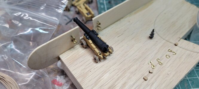
I had already drilled the 4 holes for securing rings on the inner bulwark walls.
That was tough, my dremmel tool's chuck is too big for a very small drill bit, so I had to drill each by hand. Not a fan of that!
...I ordered a little battery powered dremmel style tool and it is coming today for the rest of my project. I also order 20 or so teeny tiny drill bits.

I installed the rings, but after doing some testing and thinking, that is a mistake.
Best to drill the holes, rig up the cannons with their proper rigging ropes and the rings attached and then glue those rings into place.

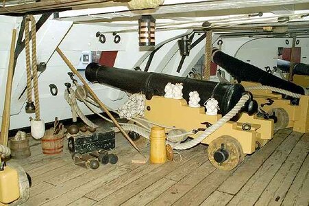
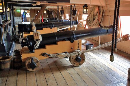
All the pictures, both live shots of the ship and blue print pics of the cannons show that the outhaul tackle lines are all attached to both the inner wall and the base of the cannon with hooks.

Oh!!! I also cut the heads of some of the little nails and glued them into the trunnions and painted them. They seem fine.

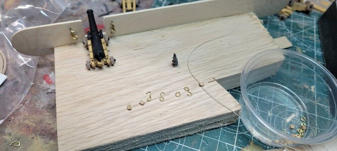
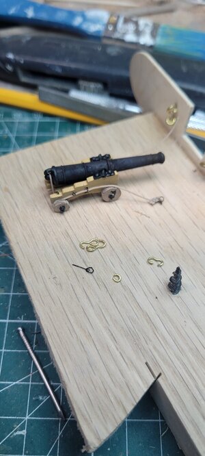
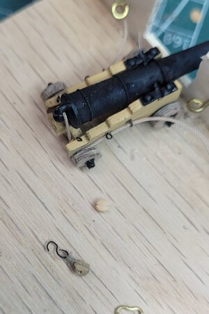
Trying to create a hook that scales well has been very tough. I have a spool of .6mm brass wire, but that is too thick as you can see. I can bend it and the shape it, but they seem just too big. In the end, it may not be as important on this deck, but the upper cannons will be visible and I'm hoping my work and practice below decks will pay dividends where it counts!

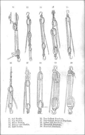
Also, all the diagrams call for a single block at the back and a double block in front for each outhaul.
This kit only requires 2 single blocks. The single blocks are 2mm and I found some 2.5mm double block, which I ordered.

I have been experimenting on tying off the single blocks and one of my premade hooks with .1mm line. It is very tough and requires 3 hands and that is even using a little holder with alligator clips to hold the hook part! I did one, but the hook is just HUGE!!!!!

Now I am thinking that since I am not going to be using all the rings for the other 20 cannons, so I am going to try bending one of those into a hook and see how it looks on a block. That may be as close as I can come with the materials I have. I know I have stranded marine wire, but my guess is that is no thinner than the .6mm brass I have. (I am talking about photo etch part #480)

I will dive back into it and let you know!

20240717_134749.jpg

20240717_140522.jpg

20240717_142559.jpg

20240717_151149.jpg

20240717_151155.jpg

20240717_151220.jpg

20240717_161723.jpg

20240717_161727.jpg
 
Also, all the diagrams call for a single block at the back and a double block in front for each outhaul.
This kit only requires 2 single blocks. The single blocks are 2mm and I found some 2.5mm double block, which I ordered.
According to Adrian Caruana in The History of English Sea Ordnance only 32 pounders and above would have a single and double block for the running out tackle and train tackle. All other calibers would have two single blocks for each tackle.
I don’t think these are blocks but the leading end of the sheet connects to the hull
James Lees gives the following description on page 77 of The Masting and Rigging of English Ships of War. "The standing part was seized or hitched to an eyebolt in the ship's side. The running part was rove through the sheet block fastened to the clue of the sail, led aft through the sheave in the bulwarks and secured to the clearts or kevels on the inside of the bulwarks."

Hope this helps
Allan
 
invisible sheeting blocks that are installed in the hull.
Good morning. The rigging of the Victory is vast but makes for a brilliant model. I don’t think these are blocks but the leading end of the sheet which is attached to the hull with a metal eyebolt. The running end run through a sheave in the hull to a cleat on the inside. Cheers Grant
 
Good morning. The rigging of the Victory is vast but makes for a brilliant model. I don’t think these are blocks but the leading end of the sheet which is attached to the hull with a metal eyebolt. The running end run through a sheave in the hull to a cleat on the inside. Cheers Grant
Apologies sent this twice.
 
According to Adrian Caruana in The History of English Sea Ordnance only 32 pounders and above would have a single and double block for the running out tackle and train tackle. All other calibers would have two single blocks for each tackle.

James Lees gives the following description on page 77 of The Masting and Rigging of English Ships of War. "The standing part was seized or hitched to an eyebolt in the ship's side. The running part was rove through the sheet block fastened to the clue of the sail, led aft through the sheave in the bulwarks and secured to the clearts or kevels on the inside of the bulwarks."

Hope this helps
Allan
Hi Allan;

I believe that if I do it correctly in the end, the rigging will be as you quote. The diagrams I posted show what you wrote, the standing end is seized or attached to the hull and the running side does got to a block, back down, through the hullside sheaves to the interior of the ship to be secured on a cleat.

Much appreciated!

Also, I can't as much spec on a 32lb cannon, but a 30lb would weigh around 6600lbs. All of the pictures I have of cannons on the lower decks of the actual ship seem to show a single/double block setup? I attached some pics, but they may be hard to zoom into.

I was actually excited about that comment though, but I will look some more before I decide what to do. I think the double blocks may come today and I will try one using the PE parts as hooks.

Thanks so much for taking the time!
Chris

Cannon - Lower Deck.jpg

Cannon 32 Pounder.jpg

Lower Deck - Cannon (2).jpg
 
All of the pictures I have of cannons on the lower decks of the actual ship seem to show a single/double block setup?
Yes, there is a double block at the eye on the bulkhead and a single at the carriage on the running out tackle. Smaller caliber than 32 pounders would have two singles. Caruana was the expert of experts but note that there is very little that is absolute when it comes to rigging.
Cheers
Allan
 
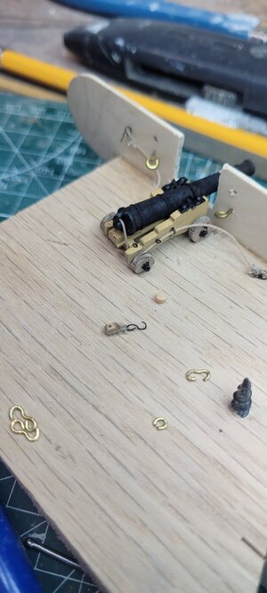
The pics below are a very fast and sloppy attempt at trying to create smaller hooks for the cannon outhauls.
My daughter and grand-daughter are in town and during her nap, I went down to take a stab at what I'll be looking at with a few hours to dedicate.

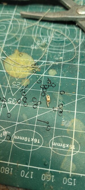
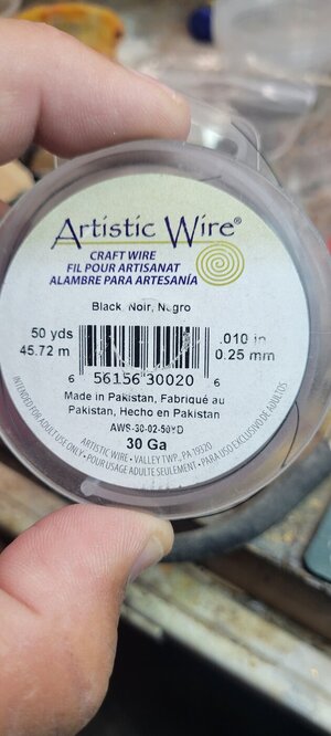
The 30ga wire seems to be a perfect size to create rings and hooks. At that thickness, or lack thereof, they are NOT going to be sturdy, but I think they will scale very well. I also bought black wire, which is nice.

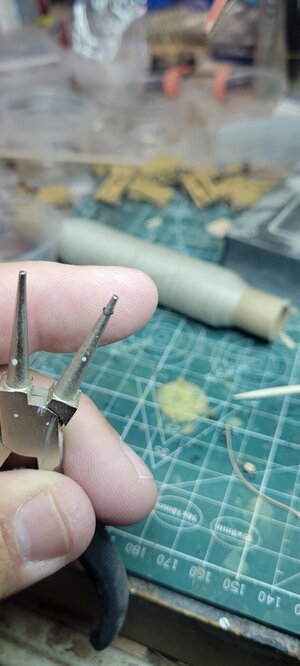
I know there is a pic of a ringlet on some round nose pliers, but I wrapped about 20 or so coils on a finish nail and then used my cutters to cut into the spiral and make teeny tiny rings. They need to be shaped a bit and once in place a dab of CA glue will keep them from separating.

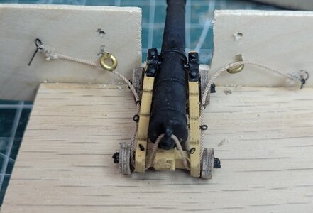
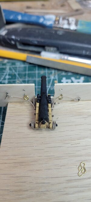
My practice cannon already has the breach line in place, future cannons will have the ring in place to run the breach line through along side the cannon base.
Using PE part#480, I was able to add a ring. I then tried to tie off the breech line through the ring. This is my first time trying to do some rigging. It is tough and there is a learning curve needed to make my fat, shaky fingers work.

Also, full size cannons actually show that the breaching line is knotted to the ring attached to the bulwark wall and the bitter end is then whipped in place.
I tried that on the starboard side and it just creates a big ugly blobby mess.

On the port side, I just pinched the breeching line and then tied it off with .1mm line. I then added a second tie off about 1mm or so below it.
My problem is that cutting the excess thread isn't perfect. I thought I had a good set of small surgical scissors, but the very tips do not cut very well at all. I have a pair of like a Wescott type and they cut very well and very close, but they have a very blunt nose for this type of close in work and I just know if I am not careful, I am going to cut a piece of rigging some day....guarantee!!!!

I also received the 2.5mm double blocks. They are worlds apart from the kit blocks. I almost want to purchase more of the these and the single blocks for the top deck cannons.

You can see my work table is just a clutter of little parts and tools. I plan of putting everything away and creating a work space (in a little bit too, because I keep dropping the little parts when they PING away!!!) and taking a stab at the next cannon.

But I think this may work!

20240723_125049.jpg

20240723_125057.jpg

20240723_130659.jpg

20240723_131702.jpg

20240723_132550.jpg

20240723_132601.jpg

20240723_132817.jpg

20240723_134506.jpg

20240723_134531.jpg

20240723_134543.jpg

Boy's Manual Of Seamanship And Gunnery - Purchases.jpg
 
Nice, I like your ring making method. I will use this method in the future, cause I too have heard the sound of "PLING" when working with small metal parts. Thanks for the info.
 
Well....after 40 years of work, I retired 2 years ago and have been trying to find things to do. As a teenager, I certainly worked on plastic models, with all their glue stings and poorly fitting parts and horrific paint jobs. I remember getting a small Cutty Sark wooden model, with poor instructions and parts that were only printed to wood sheets. Everything had to be cut out and even the hull was a solid block of wood that had to be shaped and sanded....never came close to finishing.

Last year I took on a plastic model, Trumpeter's Titanic. It was a massive undertaking and took just about a year to finish. I had to learn how to handle photo etch, a paint gun, the use of CA glue and manipulating teeny, tiny parts. I took most of last summer off in the build as I own a sailboat in upstate NY, USA and that took priority, but I finished her last November or so. Is she a show room piece? Lol, no, but I am very proud of how she looks.

I have fairly good wood working skills and can problem solve a lot of things with wood. I love sailing and have always wanted to buy one of those pre-made wooden ships for my office. The ones that cost about $500-$700 USD. Instead, I decided, why not try to build one!!!!

I know this kit is VERY hard and having never even tried to build a wooden model or the subsequent issues and tasks concerning rigging, I just wanted to take a stab at it.

So I found a kit in stock in the UK through Arrow Models. I ordered her and within about 2 or 3 weeks it arrived in the USA. Arrow did a great job and while I was a bit nervous working with an overseas company where I could find little feedback, they were tops! Great communication and great customer service.

There are a number of builder logs for the HMS Victory and a few YouTube video logs that I am using. I thought I would add a log that is from a person with absolutely NO experience with this type of kit and certainly a kit that requires a high degree of skill or expertise or as is my hope....just the patience and perseverance to gut it through!

I've posted a few Titanic pics in this post, I promise going forward it will be all Victory all the time. I just want to see how the posting process works and I will start adding right away. As of Feb 21, 2024 I am on the first planking task, about 5 planks up. So.....I'll see you at the finish line and thank you!
ChrisView attachment 433093
Hallo @team118
we wish you all the BEST and a HAPPY BIRTHDAY
Birthday-Cake
 
Back
Top