


So as I mentioned a did things a little differently for these replacements.
It turns out I was a little over enthusiastic about how many planks I had thinned down to 2.5mm, most of them are actually at 3.0mm and I don't check which were which. This messed with my replacements a little bit, but more on that later.
This time, after cutting out the new ribs I used a lightboard to trace the outline of the ribs on the back of their pages. I realized later I could've just printed two copies and glued one on backwards and use that to cut them, but oh well.

Using the two sided method I feel like the making of the ribs went much faster but not much more accurate than the ones I had made up previously.


I decided to remake rib W and the half ribs 4/6/7/8.
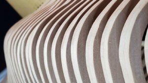
I also did some more test fitting and found that I really could've remade half the ribs to make them look better. And in effort to not get stuck at this stage I decided to just start gluing. Time to move on!
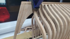
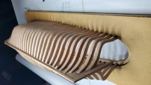
1. I put in rib A and rib W in place and glued them.

2. I started from A and began gluing down from the bow. I fit the each rib into the keel, tighten the grip, then tighten the grip where the rib touches the jig for optimal fit. Not all ribs are the same length and not all ribs have the same depth at the part where they meet the keel, so I felt this method would give me the most consistency.

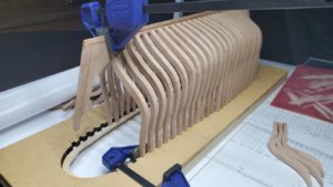
3. We're off to the races. Glue, glue, glue.

I'll glue in all the full ribs, then I'll revisit the half ribs. Not all the new ones are completed and I may need to make a few more, but I'm moving forward.
It turns out I was a little over enthusiastic about how many planks I had thinned down to 2.5mm, most of them are actually at 3.0mm and I don't check which were which. This messed with my replacements a little bit, but more on that later.
This time, after cutting out the new ribs I used a lightboard to trace the outline of the ribs on the back of their pages. I realized later I could've just printed two copies and glued one on backwards and use that to cut them, but oh well.
Using the two sided method I feel like the making of the ribs went much faster but not much more accurate than the ones I had made up previously.
I decided to remake rib W and the half ribs 4/6/7/8.
I also did some more test fitting and found that I really could've remade half the ribs to make them look better. And in effort to not get stuck at this stage I decided to just start gluing. Time to move on!
1. I put in rib A and rib W in place and glued them.
2. I started from A and began gluing down from the bow. I fit the each rib into the keel, tighten the grip, then tighten the grip where the rib touches the jig for optimal fit. Not all ribs are the same length and not all ribs have the same depth at the part where they meet the keel, so I felt this method would give me the most consistency.
3. We're off to the races. Glue, glue, glue.
I'll glue in all the full ribs, then I'll revisit the half ribs. Not all the new ones are completed and I may need to make a few more, but I'm moving forward.


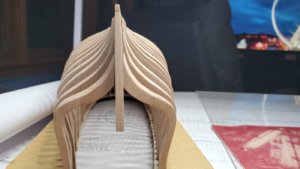

 , so putting in all the can't frames went rather smoothly. The bracing of the frames for drying got kind of elaborate at times, but with a little shaving and finishing everything worked out. In the end I redid half the cant frames in the bow.


.jpg")


