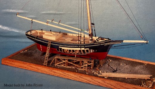
HM Armed Cutter Alert (1777) - Vanguard Models - 1/64

Metalwork - Pumps and Gratings

There are 75 days left in the year and it's now clear to me that I won't be starting my next project on New Year's Day. In fact I'm so mindful (living in the here and now, man), that all future plans have been erased and I don't even know what the next project will be yet. I'm just aiming to enjoy a little boat building somewhere in the day. And today was fun, fun, fun as I occupied myself with two of my favourite things - corrosive chemicals and fire.
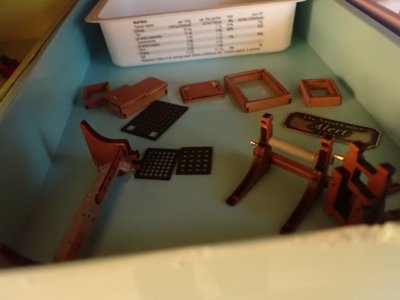
PA170001.JPG

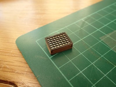
The chemical was antiquing fluid. I have no idea what it is but it blackened these hatches and the nameplate in seconds with one application. I polished the nameplate afterwards, thinking of brass nameplates sometimes found on doctors doors where the brass has been polished so often that the background plate also begins to shine.

The Fire was the best bit.
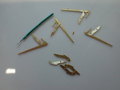
PA170002.JPG

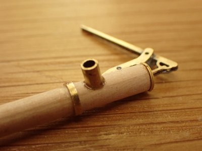
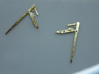
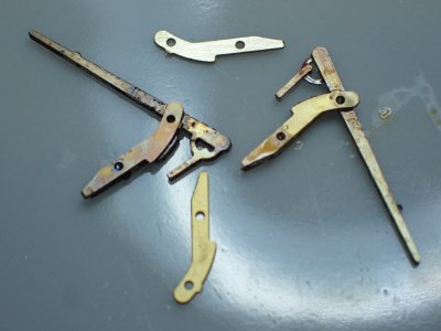
These are the parts of the elm tree bilge pump upper mechanisms. The centre parts, the handles came with two spares. I guess this is due to their extreme fragility. It seemed sensible to anticipate disaster and use two pieces soldered together. With the outside 'cheeks' of the pump soldered to the outside of the two center parts the pumps would be a good sturdy sandwich of brass and lead and perhaps they won't get broken at all.
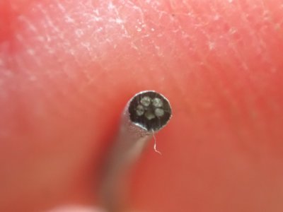
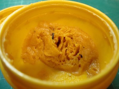
PA170004.JPG PA170003.JPG

My solder comes with flux built in but that's not enough. Before that can melt and flow, I will already have applied heat to the brass, causing oxidation which will prevent the solder sticking. Flux needs to be applied to the brass first. I've had this snotty potful of flux for 40 years now and don't expect ever to use it up.
PA170006.JPG

There's two of the centre elements polished clean with a glass fibre contact cleaning pen and fluxed on their mating surfaces only. We can use the oxidation of the other side of the pieces to keep solder away from places we don't want it. It went very well although I haven't done any soldering for a year or more. I find that it's like riding a bike, uncomfortable and dangerous, but easy to remember.
PA170007.JPG

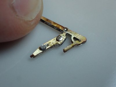
This is the two centre sections soldered together having a cheek piece applied. The mating areas have been cleaned once more. I cut some slices from my solder and stuck them into the flux. There are two here though for the larger centre section joints I used four. I don't use much as it will flow very well when melted and I don't want any overflow. (That's the corner of my fingernail, top left, for scale.)

This is the good stuff, real proper LEAD solder which again I've had for decades. It flows infinitely better than whatever rubbish they have to make the lead-free junk out of.
PA170011.JPG

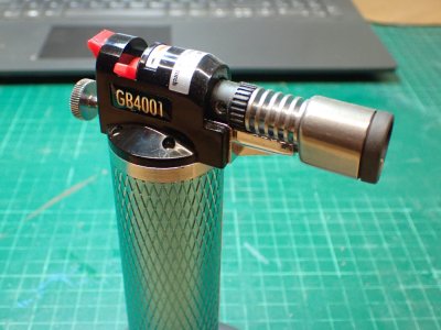
If I was using a soldering iron, I'd have to find a way to hold the parts together while my aged and trembling hands brought the iron into contact. Instead, whenever I can I use a soldering torch. It is so much easier than an iron and since the flame is only on the job for such a short time, fractions of a second, it can even be used for soldering strops around blocks with no damage to the wood. I'll show you that later in the build.
PA170008.JPG

This shows the first cheeks in place with the final layer of the sandwich about to be soldered on the other side.
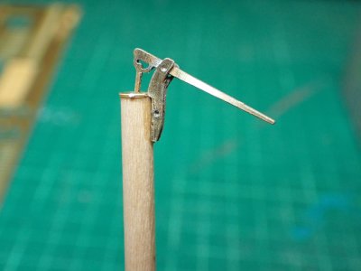
PA170010.JPG

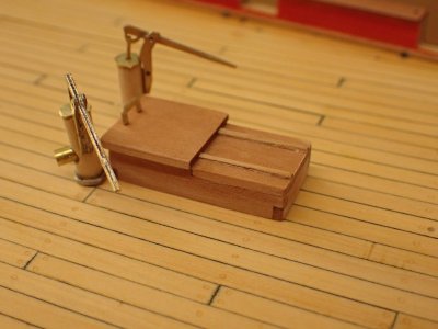
And there it is, cleaned up and superglued to the top of its elm tree. They actually used the whole trunk of the tree, bored out and fitted with a two valve mechanism like a stirrup pump, to lift water from the bilges to the deck and then over the side. Elm was favoured for the job for the same reasons it was used for keels. It was straight, strong and very water resistant.

Next update should show the rough tree rails in place. What a wonderful name that is!
 
Last edited:
Pumps - Again

I made a start on the rough tree rail and other things attached to the bulwarks but became distracted by the pumps.

I established the locations on the deck from plans in the AotS book and drilled holes. I've lost faith in the kit plans which are of course, as simplified as the kit itself. When the pumps were in the holes they looked as though there was something missing. Not many items pierce the deck without some sort of seal, a skirting board of sorts, and a pump- a big wet thing, surely would be sealed against the deck to prevent it's water running back inside? I decided to make a sealing ring of some kind.

At this point I hadn't looked very hard at my reference book. I'm not a scratch-builder and despite making several models like this, I'm not very experienced at using plans. I must tell you, until recently, they made little sense to me at all. Recent study of books and buildlogs on model building have made a lot of things much clearer and I'm now beginning to learn the skill of reading a reference plan PROPERLY. That means looking at every line and working out what it means in three dimensions. This skill is so weak and new to me that I just forgot to look at the drawings of the pumps at all at this stage in (last night's) proceedings. I just improvised.

PA180002.JPG


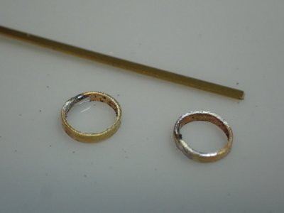
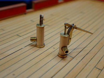
I used a brass strip saved from a photo-etch fret, bent it into a circle with some jeweller's pliers, and quickly and easily soldered it into a ring that would be a tight fit on one of the pumps. The diameter of the dowel is 4mm. Seeing the rings enlarged like this is a terrible shock - I thought they were a lot tidier than that! Under paint, they will look better, I hope. The second ring was neither quick nor easy and I needed three attempts to make one that was Goldilocks, neither too big not too small.

PA190003.JPG

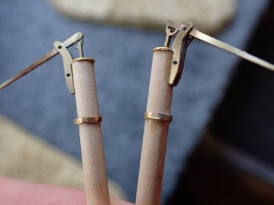
On the pumps they look fine and I glued them to the dowels while the pumps were resting on the lower deck, 30mm down, leaving the correct 10.5mm sticking up.

PA190004.JPG

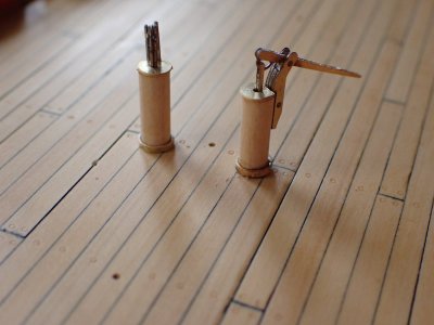
I think that's more credible with the rings than without and if I use enough thick paint It will pass. I patted myself on the back and looked smug for a while. Belatedly, it occured to me to look at the plans in AotS Alert.

PA190005.JPG

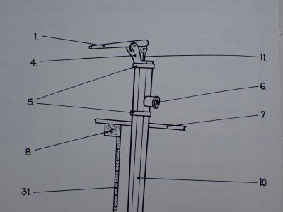
Oh dear. The dowel could have been made octagonal in section. It DID have a ring around it but not actually down on the deck so my imaginary improvisation wasn't far off. But look at #6, a big fat outlet pipe which changes the appearance of the whole thing. It was too late to change the dowel profile or the ring but I had to fit an outlet. I was annoyed with myself for failing to use my reference properly - it was right there next to me! But that was this morning. It's evening now and I'm thinking that The Strange Affair of the Modeller Who Didn't Refer to His Reference, is a short story that will stick in my mind forever. Another lesson learned, another step on the road to Pof and maybe one day, scratchbuilding.

PA190006.JPG

I Araldited a short piece of brass tube into a hole drilled into the dowel. I did not incorporate a flange and I set the outlet on with a noticeable downward tilt, despite the reference. My admittedly inconsistent way of thinking is that it's OK for me to build my model in a way that pleases me but only after finding out (if possible) what it should have been like. To be honest there's a little bit of "but I don't know how to make the flange anyway" involved in the decision. Heck, nobody's perfect.

PA190007.JPG

I have a feeling that over the coming years as my plan reading skills develop and I learn how better to realise the plans in wood and brass, I'll lean more in the direction of accuracy. I believe this to be the case because as I look at those pumps I am still thinking of ways that I could have done those outlet pipe flanges, dammit!
 
Deck Improvement


View attachment 477739


Guns, bitts, companionways, hatches - there's a mounting list of things that will impede access to the deck itself in the coming weeks. It's important that I'm completely happy with that deck before I stick anything down. Today then, I made a tiny improvement, I think. Bearing in mind that it's not quite finished yet, can you see the difference?

That's right, it now has treenails. Actually, many more than three! :D

View attachment 477738

Here's a close up.

Whether or not to make treenails on a 1/64 model is a matter of taste, in my view. There's a strong argument against in the fact that they are more or less invisible close up and from 128 feet away (scaled up from looking at my model from two feet off) totally invisible. Yet am I to be enslaved by the evil mistress Accuracy?

I'd rather be seduced by Accuracy's nicer twin, Beauty. I decided that my deck would be slightly more beautiful, or at least would appeal to Beauty's second cousin Interest if I had a bash at suggesting deck beams and other underlying structure. And that's my reason for simulating the treenails that held the deck planks down. I'm an old engineer as well as an old romantic. ;)

View attachment 477737

I made a tool by fitting a paintbrush handle to an old hypodermic needle I found in the park. No' not really. It's a blunt ended hollow needle for applying glue with a syringe. I sharpened it on fine wet and dry paper so that it would act as a cookie cutter. In use I press it onto the shellac'ed deck and move the handle in a circle which cuts through the varnish and impresses a circle on the planks. The needle isn't glued into the handle because over time it fills up with debris that needs to be cleared by pushing a fine wire through it.

View attachment 477736

Then, to develop the effect into visibility, I applied a thinned coat of Button Polish (dark shellac) This either penetrates the cracked layer underneath or just fills in the circle, I can't tell without a microscope.

The final step, which is not yet completed is to rub away the rest of the dark shellac with 0000 wire/steel wool. I put too much button polish on so it's a long job.

The deck is slightly more yellow at the moment but since it wasn't oak planking but the cheap softwood, Deal, I don't think that's a problem. It might be a little darker at the edges and in places across the deck but again, I think a pristine white surface is inappropriate here. If they had holystoned it, they would have been through to the hold in a month!

~~~~~~~~~~~~~~~~~~~~~~~~

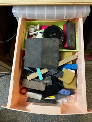
I did one more thing today which will move matters along - I sorted out the mess in my Alert's cardboard box. It was full of scraps of wood, various paints, empty frets (never make empty frets, my Dad used to say), unread notes, copper plates etc etc etc . Now it only contains the things I actually need. It was a pleasure to tidy that lot up and find out how little wood there is yet to use. It was a caution to find packet after packet of blocks and deadeyes and rather a lot of string...
I tried the same method today. I took a tip from a gel ballpoint pen and made it imitate nails. There are pros and cons. Plus, it's quick and easy. The downside is that even under oil, you can't always see this imitation. You can see it clearly from a certain angle, but you can't see it at all from another angle. I'll try bitumen coating on the new tests. Maybe he'll show those dents from the handle.
 
Smithy you never fail to impress and more importantly, inspire me.
Brilliant mate, loving the awesome attention to detail, an inbuilt passion (curse)

TSC Thumbsup :cool:

The trick seems to be accepting my inconsistencies. I’ll spend two days on the pumps and then dash through something when I’m not in the mood. That’s ok with me. It’s only a problem if I say it is. Ha!
 
Musings on ‘Super-detailing

I’ve been thinking about those pumps and about a handrail and interior bulkhead that @The Ships Cat added to his Endeavour. It’s reminded me how much difference a little super detailing makes. When I was building aircraft I’d always add seatbelts, a pilots helmet and maps in the cockpits. I’d open up some panels and make avionics black boxes inside, maybe make an engine. And then there would be a bit of weathering, peeling paint and oil stains. It all helped make my model mine, you know, but mostly it added ‘human interest’ showing where the little imaginary people interact with the machine.

I’ve made a lot of big changes from the kit spec to Alert but I find I’ve neglected the small but effective details. I could have had steps leading down the companionways or left the main hatch off to show the stowed cables or opened the bread room hatch. As it is, with all the hatches closed there’s not even a clear sense of human scale.

It’s too late for those internal things on this build but that handrail has reminded me about all this stuff and prompted the improvements to my pumps (and the proper research that led to them). Is it fanciful of me to think that the outlet pipes make it easier to imagine a pair of tiny sailors on each handle, pumping for their lives, with water gushing over the decks?

I’ve been so concerned with getting the basic carpentry right that adding ‘human interest’ details has suffered. I think I’ll revisit some of the sub-assemblies I thought were finished and see where I can make their use by people a bit clearer.
 
Hi Smithy, I've been "off air" for sometime and only just started reading your build thread and am finding it very interesting. Some great tips to be had, thanks for sharing with us.
 
Hi Smithy, I've been "off air" for sometime and only just started reading your build thread and am finding it very interesting. Some great tips to be had, thanks for sharing with us.

Welcome back, ancient one, and welcome aboard! I’m glad you find my scribbling interesting. Smiles.

(The emoticons on my phone don’t work so I write them in words.)
 
Rough Tree Rail (etc)


PA200002.JPG

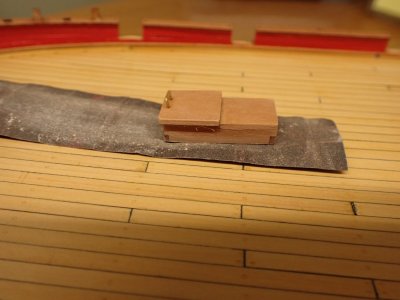
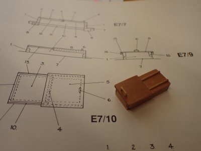
I went back to those companionways and hatches and compared mine with the AotS drawings. The after companionway needed its wide overhanging eaves sanding back and a curve sanded into its bottom. The photo shows a handy way to do this - hold a piece of sandpaper on the deck and rub the part on it. The deck itself cuts the correct curve in the part.

PA200003.JPG

Here's one of those inconsistencies of mine. The plans do not show runners for the sliding hatch but I think that adding them tells a story to the landlubbers who will be admiring this model (he hopes) when it's done.

PA200004.JPG

It looks a lot better without the gingerbread cottage roof. I've also adjusted the angle of the forward and aft faces of all of these deckhouses. They weren't perpendicular to the deck but to the horizon.

PA200005.JPG

The Captain's private companionway and skylight looks infinitely better with 'glass' in the windows. It was a piece of clear acetate from a meat pie box.

PA200006.JPG

These bits will hold the bowsprit in that square hole.

PA200007.JPG

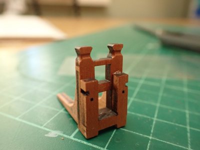
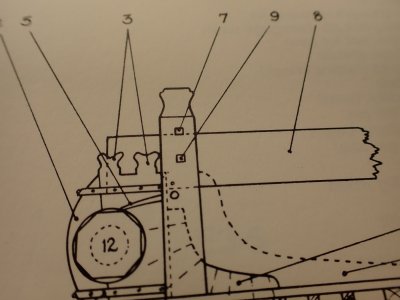
But the top beam is wrong. Part 7 is an iron bar, not a wooden beam. I've removed the beam and will drill for the pin when I've built the bowsprit. Part 9 is the bowsprit fid and I'll incorporate that too, though I won't make it functional.

PA200009.JPG

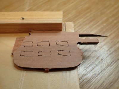
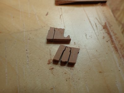
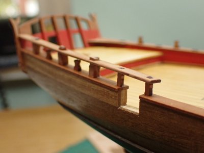
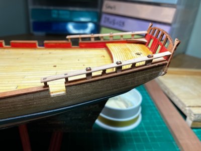
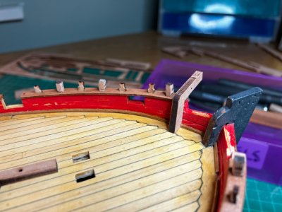
At last, onto the rough tree rail. The small parts in the thick pear fret were very difficult to cut out with a knife so a saw was needed.

PA200010.JPG

These pieces didn't fit well and by the time I'd made them fit they were a little indistinct in shape.

PA200012.JPG

The six parts were also difficult to line up. Eventually I glued the various stanchions into the rail and let them set a little. Once they stopped falling out but were still bendy, I could glue them into the cap rail as you see. I only did one side today as I have a slight cold and feel very sorry for myself (no-one else will, so why not?) and deserved a nap.

PA200011.JPG

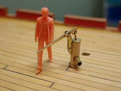
And finally, I've received some figures to help me grasp the sizes of everything. I'm not used to 1/64 scale the way I am with 1/48 or 1/35 and the little guy is really useful to me. Those pumps are huge!

So that's it from me for the day, many tiny pieces of work, but it's still progress, still satisfying despite the ague.
 
Back
Top