HMS Alert [1777] 1:48 POF by serikoff. (Two hulls: skeleton and fully rigged)

But they look so good, you should be happy. :) I would bet seeing this great array of photos and how well these frames are "shaping up" is giving a lot of members a goal to shoot for.
Allan
Absolutely! This process makes frame construction almost flawless. Note, I said almost. ROTF You're doing a fantastic job Serikoff!
 
Very nice work and a very clever kit design.

The original plan was to build this kit twice. I assume you are only working on one set of frames at a time?
Yes, the kit is really very good. You can achieve good results. Yes, I want to build two hulls, but not identical ones. I want to build one as a skeleton (from the kit), and then scan it and carve it from one piece of wood, so that later I can sheathe it with slats and make the deck stuffing and install the mast and sails. So in fact, I kind of make two hulls, but in turn, continuing to build the second one after the first from the same place. I hope I explained it clearly, otherwise I hope the translator will translate everything correctly))


Absolutely! This process makes frame construction almost flawless. Note, I said almost. ROTF You're doing a fantastic job Serikoff!
Thank you for your words)) There is always something to strive for and always room to grow)))
 
Moving on at a fairly good pace. I didn't count, but I definitely made more than half of the solid frames. When I finish, I will show you how to grind such horseshoe-shaped frames so as not to damage them. In the meantime, a couple of life hacks when working with templates.

The most obvious, but not always everyone does this (which leads to deformation when glued or glued to the steps in the glue seam). This is a fixation of glued fragments. The simplest method is to put the template on a perfectly flat surface, and put the load on the frames. In my case, these are dumbbell pancakes.

Alert 146.jpg

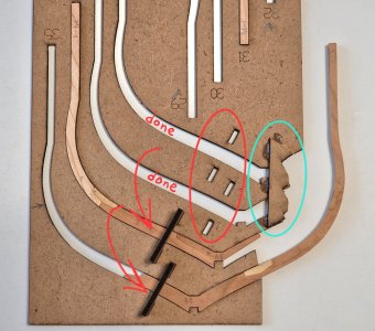
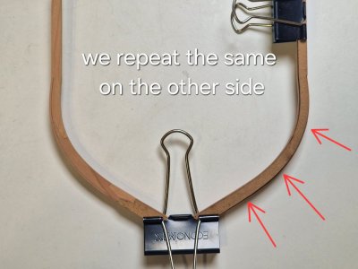
The second point is the clamps to maintain the correct (original) pattern geometry. So, there are only 9 of these latches. And if you glue the second parts of the frames, then only a maximum of 2 frames can be glued at a time. And in order not to wait until the glue dries and assemble on several templates at once (I do on 3-4 at once), these latches are not enough. Therefore, it is possible to glue ready-made fragments as they are manufactured and no longer use latches in this zone, but use them on new templates.

Alert 147.jpg

As shown in the photo below: in the green oval there are already permanently glued fragments, and then in this area no latches are needed (shown by the red oval), and the latches can be used further (shown by the arrows). And those latches that are free - use on a new template.

Alert 148.jpg

At this pace, I will soon finish gluing all the frames and you can start contouring them after grinding...

Ship-1
 
A little update and a couple of thoughts...

To date, it remains to glue another 8 halves of frames, i.e. in fact 10% of all 41 solid frames. Then grinding everyone and you can start contouring those that are needed, there are about half of all 77 of them. But it still feels that I am already at the finish of the first chapter...

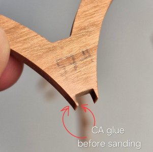
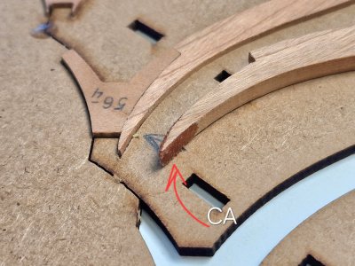
And another small life hack... so that very small edges of the workpiece do not break off (especially if it is on wood fiber), you can glue with cyanocrine that cist that can be chipped during processing.

Alert 149.jpg

Below in the photo is a part before processing glued CA and the same after processing.

Alert 150.jpg

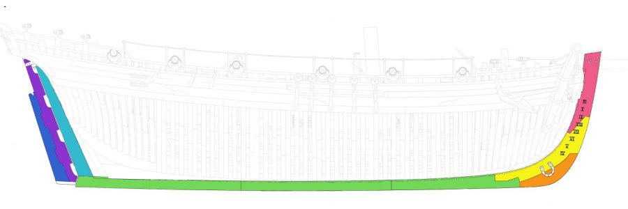
Today I also decided about wood for the keel frame for the second building, and for replacement in this one. After 1.5 months, I hope the blanks will be sawn into dies and 9 parts of the keel frame will already be cut out on them (the only thing is that I connect the bottom 3 parts and make the joint an imitation, so in fact 7 parts). And that most likely I will have already completed all the frames by this time and will collect the slipway and may even begin to collect the keel. You also need to think over the stand mount... in a word, work is in full swing...

Alert 151 Радуга.jpg

The parts that are highlighted in rainbow colors are the ones that I will redo for the set and the same second set will be for the second case. By the way, I will try to have the Latin numbers on the keel - this time. And the second is the thickening of the keel in its front upper part from 5 mm to 6-6.5 mm, as indicated in the anatomy and which is not in the kit.

Ship-1
 
1.6. Grinding

Hooray!... I finished gluing the one-piece frames together. There are 41 of them and a total of 65 frames that had to be glued together. And this stage is over. I finished it 2 days earlier than expected. Now it remains to grind them.

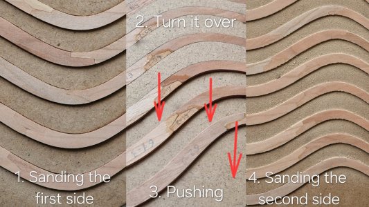
Frames that were halves I already showed how I polished out. Everything is simple there. In a stacked template, everything is first ground on one side. Turn, push and grind on the other side.

Alert 152.jpg

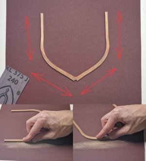
It is impossible to do this with solid frames, since they can only be side by side with halves at the same time. Therefore, the grinding method is as follows: on a sheet of sandpaper 240, we grind along the fibers, as indicated in the photo. Yes, this is long (although not very), it is not very convenient (but this is very)), but all surfaces are flat and there is no risk of damaging the frame.

Alert 153.jpg

And this is the result...

Alert 154.jpg

Left - before and right - after grinding. I think I will cope with 35 remaining ones in a day and then a more interesting procedure - contouring...

Ship-1
 
Really nice prgress. I will use the same technic for my Fly, but it takes a lot of time to prepare all the drawings and CNC files for milling.
Yes, I can imagine. But still, it takes much longer to do everything manually, without a set or without CNC cutting. When you cut out each part on a saw, process it, grind it... I take my hat off to those who do everything manually, but for me it takes too long. CNC is simply the only way out. And the better and more accurately the cutting is done, the easier and faster the process goes, but I really like it))
 
Good morning Sergey,
very neat work and a great description of your approach.

I'm also toying with the idea of getting a CNC milling machine to make certain tasks easier, but I think I'll continue to build my frames the traditional way in the future. I don't think building the frames by hand takes any longer. I need about 45 minutes per double frame. The hull construction of Le Rochefort took about two months.
 
1.6. Grinding

Hooray!... I finished gluing the one-piece frames together. There are 41 of them and a total of 65 frames that had to be glued together. And this stage is over. I finished it 2 days earlier than expected. Now it remains to grind them.

Frames that were halves I already showed how I polished out. Everything is simple there. In a stacked template, everything is first ground on one side. Turn, push and grind on the other side.

View attachment 511734

It is impossible to do this with solid frames, since they can only be side by side with halves at the same time. Therefore, the grinding method is as follows: on a sheet of sandpaper 240, we grind along the fibers, as indicated in the photo. Yes, this is long (although not very), it is not very convenient (but this is very)), but all surfaces are flat and there is no risk of damaging the frame.

View attachment 511735

And this is the result...

View attachment 511736

Left - before and right - after grinding. I think I will cope with 35 remaining ones in a day and then a more interesting procedure - contouring...

Ship-1
Good morning Sergey. Spot on :D And a cool process. Thanks for sharing this. Cheers Grant
 
Good morning Sergey,
very neat work and a great description of your approach.

I'm also toying with the idea of getting a CNC milling machine to make certain tasks easier, but I think I'll continue to build my frames the traditional way in the future. I don't think building the frames by hand takes any longer. I need about 45 minutes per double frame. The hull construction of Le Rochefort took about two months.
Wow, you have a fast pace. Yes, you are right, there is a charm in doing everything yourself or at least with CNC. But unfortunately I have neither the time nor the place to do it. I jokingly call my hobby "shipyard on a small knee" )))) because most of it happens)))

Good morning Sergey. Spot on :D And a cool process. Thanks for sharing this. Cheers Grant
Thank you for appreciating and for your comment. Glad to hear that I am doing something useful)))
 
1.7. Shaping – Refining the frames to achieve the correct geometry.

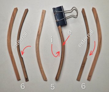
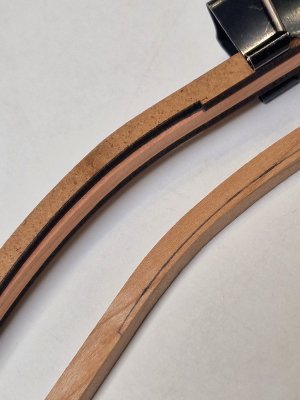
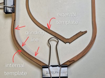
To make it easier to bring the front and rear frames into the correct geometry, you need to give the most suitable shape. To do this, the set includes not only templates for gluing, but also templates for drawing lines along which grinding will take place.

Alert 155.jpg

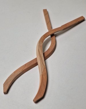
In the photo above, the 5th and 6th pairs of frames with their templates. There is an internal and external template. We must not forget that we do not make the same halves, but mirror ones! I.e. left half of the frame - mirror right!

Alert 156.jpg

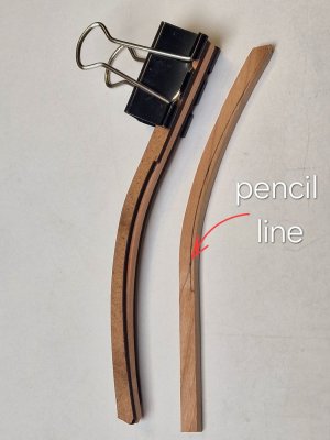
We lay the frame between two templates, fix it with clips and draw a line with a pencil.

Alert 157.jpg

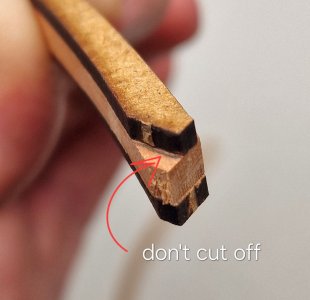
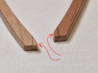
One moment... by patterns you need to cut the tips along certain lines, but I will not do this, but only draw these lines.

Alert 158.jpg

And I will cut it when I adjust the frame under the body. So I will definitely not cut off too much and the connection will be tight. I saw this mistake from other masters that after the cut they had gaps in the joints.

Alert 159.jpg

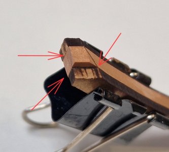
The second point - I extended the length of the grinding zone by about 4 mm.

Alert 160.jpg

In some frames, the cut point falls exactly at the end of the grinding zone. And in this place there may be processing defects, chips or grooves from the abrasive. Therefore, I raised the level a little so that the cut falls on a flat polished surface.

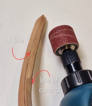
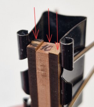
To limit the grinding zone, I made a wedge-shaped notch with a knife.

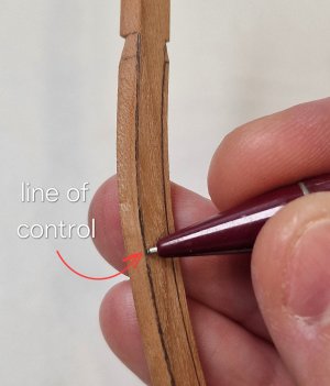
And so we have a grinding line, a notch on the edge, and now I draw a control line.

Alert 161.jpg

And now between these two lines I am grinding the frame, you can say cutting the angle. I do it with a portable engraver with such a nozzle.

Alert 162.jpg

I recommend looking at such an angle that the working plane of the abrasive nozzle is parallel to these two lines.

Alert 163.jpg

You need to try so that the grinder does not grind these lines, but only the wood (angle) between them. The control line is very important, since when working you clearly see the grinding boundary and do not remove too much!

Well, after I finish finishing the surface with a file. This is not necessary, since after assembly there will still be a general grinding of the case, but I still remove the rough scratch from the grinder and check the correctness of the geometry.

Alert 164.jpg

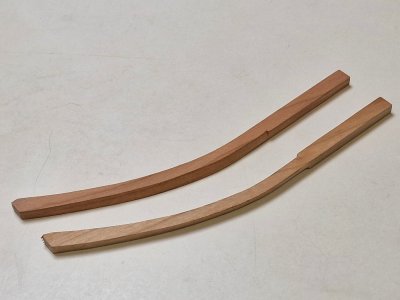
As a result, absolutely symmetrical halves of frames are obtained.

Alert 165.jpg
Alert 166.jpg
Alert 167.jpg

These frames (4th, 5th, and 6th) without lock joints, but! According to the anatomy and even according to the manufacturer's instructions, they should be with them. But I understand that this element has been simplified. I did not want to add locking joints to these frames (this is long and not so easy), but I will make imitation of these joints using a simple method. The silhouette of the lock joint is cut with a knife to a shallow depth, polished and after covering with oil, the lines stand out and become like an adhesive seam.

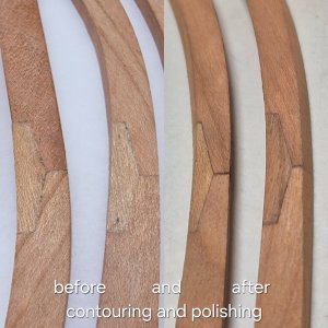
Well, this is how real locking joints look before and after contouring and grinding.

Alert 168.jpg

Another point. Some patterns are not the same length as the frames themselves...

Alert 169.jpg

... therefore, these need to be positioned at the bottom edge in the corners, and see that the side contours coincide and if there is a line for cutting the tip too, so that everything matches there.

Alert 170.jpg

Well, if there are any doubts about the accuracy of the positioning of the templates, it is better not to completely grind such frames, leaving excess for the formation of the profile after assembly. This will save you from geometry failures.

With solid frames, everything is almost the same, but for convenience I follow the following protocol.

Alert 171.jpg

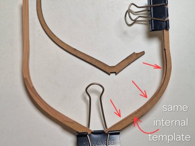
First I apply an internal template, on one side, I draw a line...
... then I turn the same template over and draw an inner line on it on the other side of the frame.

Alert 172.jpg

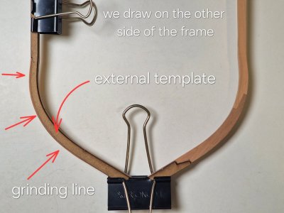
Then I turn over the frame and take the outer template and draw the outer lines...

Alert 173.jpg

First, on the one hand, I turn over the template and draw the outer line on the other side of the frame.

Alert 174.jpg

So it will be more difficult to get confused where to apply what.

All other stages are exactly the same as with halves. I have already done the front frames, the rear ones remain, and then you can start creating imitation bolts in the places of lock joints.

Ship-1
 
You can congratulate me, I have finally completed the preparation of all 85 sets of frames (and toptimbers).

Alert 176.jpg

In some places it was monotonous and 100 times repeated, but the way I did it for the first time - I really liked it! I finished contouring and the frames are completely ready to be fixed to the keel... but! According to my plan, I still have to wait for the imitation of bolts in the joints of the parts of the frames.

And here I have a dilemma. Let's just say that I am very lazy, and I do not like to do something that will practically not be visible. Everything that is inside the case (provided that I will not cut it, but I will not sheathe it with slats either) practically after laying the deck beams will not be visible so as to make bolts inside. I don't have that much time, and I don't have that much desire either.... but outside... they will somehow be missed if they are not made. Drilling and inserting brass wire is definitely not for me. Yes, this is correct, beautiful and I take my hat off to those who do this, but again, there is no time or desire for this.

1.8. Simulating bolts that join the frame parts.

And I have a little option on how to do something similar to imitating bolts, but faster, and I'm interested in your opinion. I conducted small tests coating with tung oil on small fragments of frames. At the joints, I pierced the holes with a regular needle (diameter + - 0.4 mm), at the places where the bolts should be approximately. The puncture was done to a depth of + - 1 mm. And then he polished this place a little with fine sandpaper, filling this puncture with dust from grinding. And then he wiped it with a cloth, blew it and covered it with tung oil. The oil penetrated the injection site and visualized it. And the dust that remained inside the puncture did not make the injection hollow, and the oil sealed it. By the way, I tried to close the injection site with glue, but even without it, the result was exactly the same as with it, so I removed the extra action. The result is this.

Alert 177.jpg

The photo does not convey the view that I see, but it is already clear that the dots are different from the frames, they will be simply visible without a hole in general view. Their location is only visual so far. And I remind you that the thickness of the frame is less than 4 mm! By the way, this is approximately what wood looks like without and under tung oil.

Alert 178.jpg

To be honest, I expected a little more from cherries. I understand that this is not a pear, but there is a small ripple that wears a little. I'm not even talking about the fact that there are a lot of different colors in the set and in general I already expect a traffic light on the model))) But for a skeleton it is even good, the details are separated one from the other and there is something in this. The second body will be made of pear. It is a pity that teak oil did not show itself as I wanted, but before applying the oil I will definitely make probes and give another chance to teak oil, if not, I will cover it, as I thought it would. Regarding bitumen, this issue will be resolved only after the same probes.

Well, what do you think about imitation bolts.
- to do,
- do, but only outside,
- not to do at all.

Well, when to do it? Now, while all the frames are in disassembly? Or already on the model, which is more logical, since after the main grinding you can walk with a needle, do everything and then finally polish it together with imitation (punctures). But more inclined to the second option...

Ship-1
 
Last edited:
A really good imitation, although I think they're too light for an imitation of iron nails. As for when you can do it, I think it's best when it's fully assembled, perhaps to maintain a certain symmetry. However, since I haven't built an English ship yet, I could be wrong about the approach. But that will become clear at some point.
 
A really good imitation, although I think they're too light for an imitation of iron nails. As for when you can do it, I think it's best when it's fully assembled, perhaps to maintain a certain symmetry. However, since I haven't built an English ship yet, I could be wrong about the approach. But that will become clear at some point.
You are right about symmetry. I think that on the finished case it will do more correctly. And it's hard to say about the size of the bolts. A puncture diameter of 0.4 mm is the same as in brass wire that was inserted into the holes. On the contrary, I thought that the points were not so noticeable, although the question is interesting, thank you, there is something to think about)))
 
You can congratulate me, I have finally completed the preparation of all 85 sets of frames (and toptimbers).
Congratulation, mon ami!

Well, what do you think about imitation bolts.
- to do,
- do, but only outside,
- not to do at all.
I am with Tobias, for the iron nails they are still somewhat bright. I use the brass wire on my Alert, it should oxidize in some time (years from now).
 
Congratulation, mon ami!


I am with Tobias, for the iron nails they are still somewhat bright. I use the brass wire on my Alert, it should oxidize in some time (years from now).
Thank you very much. I constantly look at your assembly (it's a pity that your pause was delayed, it's time to get back to building). For me, this is one of the best tutorials. At first, I also thought about doing it like you, but it's too long and complicated. For me, a simpler option is a way out of the situation. Yes, I understand that the punctures are a little more noticeable than the copper wire, but I think the bolts would also be noticeable, considering that they are black)) In a couple of days I will start working on the keel and I was just studying your thread)))
 
At the end of the chapter on frames, I want to add two more points.

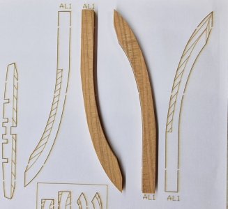
The first moment concerns the first three pairs of frames. According to the set instructions, they should be processed using special template stickers. Which is convenient on the one hand, but I do not recommend doing it right away.

Alert 179.jpg
Alert 180.jpg

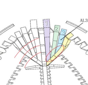
An accurate template is good, but you don't have to blindly rely on it alone. After all, we do not collect Lego, and the details are not standard and may change slightly, which accumulates errors and as a result, gaps and inconsistencies will appear without individual adjustments. Therefore, I postponed this step until the assembly of this node.

Alert 181.jpg

In this case, I can more predictably adjust the connections that are shown in the oval. And I will try to convey the bends of the case inside as much as possible (shown by red arcs), since in this place it will then be problematic to grind and correct the geometry, especially if there are holes and holes.


The second point concerns the next 3 pairs of frames (4,5,6).

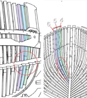
As shown in the drawing below...

Alert 182.jpg

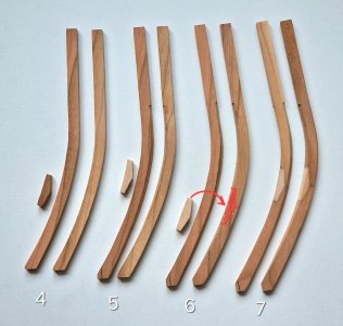
... The 4th, 5th and 6th pair of frames also have connections (i.e. do not consist of one fragment). This has already been implemented since the 7th pair. But interestingly, not only in the anatomy of this ship, these frames were prefabricated, but in the instructions for this kit, they also consist of 3 fragments (as shown in the image above). But for some reason, the manufacturer has simplified this knot, which can be corrected.

Alert 183.jpg

Anyone who wants to repeat the real connection (as on the 7th pair) on all solid frames (4,5,6) (necessarily before contouring) can cut out a fragment (as shown on the 6th frame) and then paste the connecting fragment there. Yes - this is an extra action, for a long time, but it will be right, but!

Someone who is as lazy as I am can do an imitation of this compound as follows.

Oh yes! A very important point. I did not just arrange the connecting fragments in these specific places. Because (as shown in the drawing above) - these connections are located in certain places (as if in a checkerboard pattern). And in order to know exactly where their place is, it is better to do them at the moment of assembling the case. Assemble dry frames from the 7th and further and then applying the front frames to outline where the connections will be (as shown in the drawing above in the red circle).

So, how to simulate connections on the frames:

Alert 184.jpg

First you need to attach the connector patch template and fix it...

Alert 185.jpg

... then make the outline of this pattern with the blade. The thickness of the section and its depth are very important here. First, try to do it but the probe, below you will understand why.

Alert 186.jpg

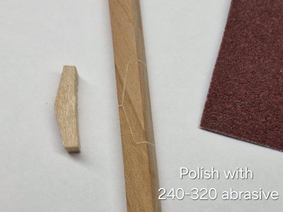
Then you need to lightly polish with sandpaper 240-320.

Well, here is the result after coating with tung oil:

Alert 187.jpg

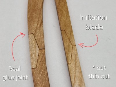
And this is why you need to make probes of depth and width of the cut. Since with a large cut, it is visualized more than the glue seam and will be more noticeable, but...

Alert 188.jpg

... if you choose the right depth and width of the section, you can completely achieve perfect similarity with the glue seam. But, there is also a consistency here. At the end of the post I will mention it, but for now I will tell you about the final version of imitation of bolts.

1.8. Bolt imitation (version 2.0)))

The first version with "punctures" for imitating bolts is a fairly fast and convenient way, but it has a slight disadvantage - punctures are a little more saturated than I would like and I will now show the second option, which I settled on.

Alert 189.jpg

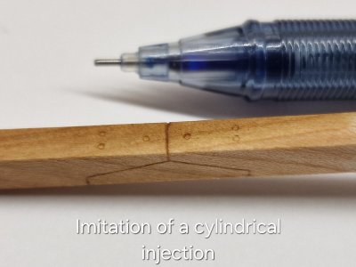
It's still the same tool I used to make simulated nails on Victory's deck. Conventional helium pen. Three balls on very small sandpaper (1000-1500) until the ball falls out. And here's a ready-made cylindrical tool. To make such a round dent (injection), you need to lean the handle against the tree and gently press the top of the handle 360 degrees (the angle of inclination is small, up to 20 degrees). Or by pressing and twisting the handle around the axis. Depending on the density of the tree in different ways. The only thing is that the depth must be small otherwise either the tree will remain inside the handle, or the dent will be very saturated in color.

Alert 190.jpg

I understand that this is not exactly an imitation of bolts, but most likely an imitation of pins, but I really like it. This is a quick and convenient way. And these punctures do not stand out as much, but they are also noticeable enough to create additional accents.

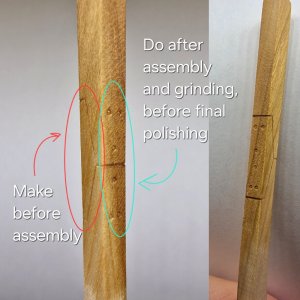
And as promised, I tell you in what order you need to do what:

Alert 191.jpg

The red oval shows the place to be made before assembly. Since these are interframe surfaces and after assembly they will no longer be accessible.

But what is shown by the green oval is that the surface (like the inner one) will be ground after assembly, and therefore imitation must be done after final grinding. Well, after imitation, you can already finally polish these places 320 with sandpaper very neatly and slightly.
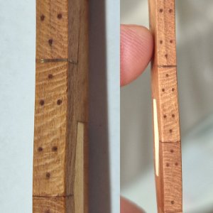
Live, imitation bolts and connections look like in the last photo on the right. There is a relief and here about polishing, I still think, you may immediately need to cover with oil so that this relief is not sealed with dust from polishing.

Well, how do you like this result?

All, now, officially we can say that this is the end of the first part)))

Ship-1

 
At the end of the chapter on frames, I want to add two more points.

The first moment concerns the first three pairs of frames. According to the set instructions, they should be processed using special template stickers. Which is convenient on the one hand, but I do not recommend doing it right away.

View attachment 513195
View attachment 513196

An accurate template is good, but you don't have to blindly rely on it alone. After all, we do not collect Lego, and the details are not standard and may change slightly, which accumulates errors and as a result, gaps and inconsistencies will appear without individual adjustments. Therefore, I postponed this step until the assembly of this node.

View attachment 513197

In this case, I can more predictably adjust the connections that are shown in the oval. And I will try to convey the bends of the case inside as much as possible (shown by red arcs), since in this place it will then be problematic to grind and correct the geometry, especially if there are holes and holes.


The second point concerns the next 3 pairs of frames (4,5,6).

As shown in the drawing below...

View attachment 513198

... The 4th, 5th and 6th pair of frames also have connections (i.e. do not consist of one fragment). This has already been implemented since the 7th pair. But interestingly, not only in the anatomy of this ship, these frames were prefabricated, but in the instructions for this kit, they also consist of 3 fragments (as shown in the image above). But for some reason, the manufacturer has simplified this knot, which can be corrected.

View attachment 513200

Anyone who wants to repeat the real connection (as on the 7th pair) on all solid frames (4,5,6) (necessarily before contouring) can cut out a fragment (as shown on the 6th frame) and then paste the connecting fragment there. Yes - this is an extra action, for a long time, but it will be right, but!

Someone who is as lazy as I am can do an imitation of this compound as follows.

Oh yes! A very important point. I did not just arrange the connecting fragments in these specific places. Because (as shown in the drawing above) - these connections are located in certain places (as if in a checkerboard pattern). And in order to know exactly where their place is, it is better to do them at the moment of assembling the case. Assemble dry frames from the 7th and further and then applying the front frames to outline where the connections will be (as shown in the drawing above in the red circle).

So, how to simulate connections on the frames:

View attachment 513206

First you need to attach the connector patch template and fix it...

View attachment 513208

... then make the outline of this pattern with the blade. The thickness of the section and its depth are very important here. First, try to do it but the probe, below you will understand why.

View attachment 513209

Then you need to lightly polish with sandpaper 240-320.

Well, here is the result after coating with tung oil:

View attachment 513214

And this is why you need to make probes of depth and width of the cut. Since with a large cut, it is visualized more than the glue seam and will be more noticeable, but...

View attachment 513217

... if you choose the right depth and width of the section, you can completely achieve perfect similarity with the glue seam. But, there is also a consistency here. At the end of the post I will mention it, but for now I will tell you about the final version of imitation of bolts.

1.8. Bolt imitation (version 2.0)))

The first version with "punctures" for imitating bolts is a fairly fast and convenient way, but it has a slight disadvantage - punctures are a little more saturated than I would like and I will now show the second option, which I settled on.

View attachment 513218

It's still the same tool I used to make simulated nails on Victory's deck. Conventional helium pen. Three balls on very small sandpaper (1000-1500) until the ball falls out. And here's a ready-made cylindrical tool. To make such a round dent (injection), you need to lean the handle against the tree and gently press the top of the handle 360 degrees (the angle of inclination is small, up to 20 degrees). Or by pressing and twisting the handle around the axis. Depending on the density of the tree in different ways. The only thing is that the depth must be small otherwise either the tree will remain inside the handle, or the dent will be very saturated in color.

View attachment 513224

I understand that this is not exactly an imitation of bolts, but most likely an imitation of pins, but I really like it. This is a quick and convenient way. And these punctures do not stand out as much, but they are also noticeable enough to create additional accents.

And as promised, I tell you in what order you need to do what:

View attachment 513226

The red oval shows the place to be made before assembly. Since these are interframe surfaces and after assembly they will no longer be accessible.

But what is shown by the green oval is that the surface (like the inner one) will be ground after assembly, and therefore imitation must be done after final grinding. Well, after imitation, you can already finally polish these places 320 with sandpaper very neatly and slightly.
Live, imitation bolts and connections look like in the last photo on the right. There is a relief and here about polishing, I still think, you may immediately need to cover with oil so that this relief is not sealed with dust from polishing.

Well, how do you like this result?

All, now, officially we can say that this is the end of the first part)))

Ship-1

Hi Sergey. I made the imitations on the frames the same way. In mind that they hard to see when the frames are installed.
But nothing beats 'real imitations', so drilling and filling. The biggest factor is time. ……..
Regards, Peter
 
Back
Top