• LUCZORAMA SHIPWRECK SCAVENGER HUNT GIVEAWAY. 4 Weeks of Fun • 1 Legendary Prize ((OcCre’s Fram Ship)) • Global Crew Welcome!
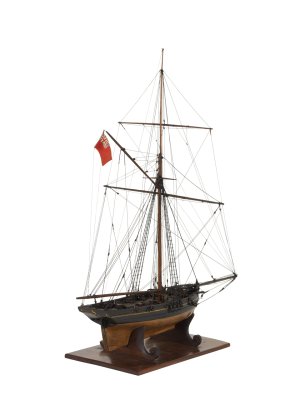
    **VIEW THREAD HERE**

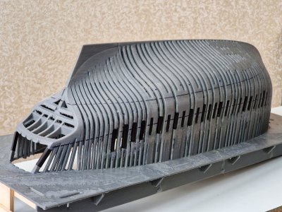
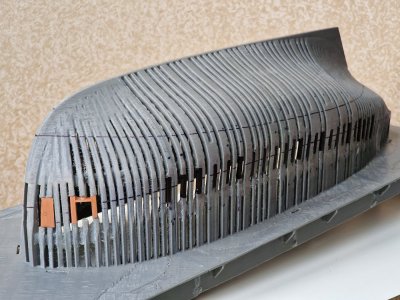
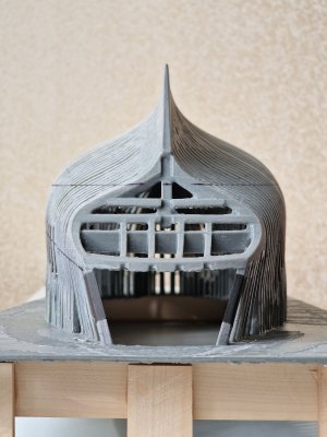
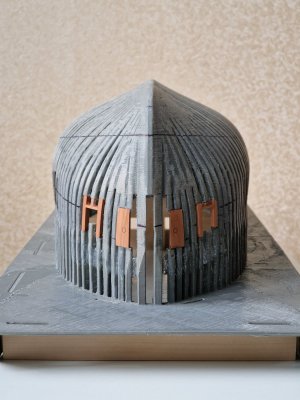
HMS Alert [1777] 1:48 POF by serikoff. (Two hulls: skeleton and fully rigged)

the steering wheel will have a rounding on the leading edge.

Hi Sergey
Assuming you mean the rudder, it's interesting that the leading edge, or bearding, was a separate piece and the bevel changed over time, at least on British ships. I have no idea what it was prior to 1650, but according to Goodwin it was only 30 degrees from 1650 to 1720, after which it was 45 degrees. This angled (not rounded) piece of elm or fir went from the keel to the point where the sternpost terminated at the top. A piece with similar angles was fayed to the after edge of the sternpost. Some builders like the use of a different species of wood even on a model to show it more clearly. Were there exceptions on these angles?? I would not be surprised if there were, as there seem to be exceptions on nearly everything before the use of computer controlled manufacturing . Looking at a chart of dimensions for the pintles and gudgeons given on page 130 of The Construction and Fitting of English Ships of War, it appears the gap between the rudder bearding and matching piece on the stern post is about an inch.
Allan
 
Many kit companies would benefit from a thorough study of your build log photos when designing their instruction manuals. :)
Allan
Judging by the forum, Trident listened to modelers and made changes and amendments, although this is a very rare occurrence. I will say more, many manufacturers really do not like it when someone deviates from their instructions and does it their own way. But thanks for the compliment. I am doing it for myself, that is why I want to implement this kit as best as possible.

Hey Sergey,

once again really well explained and also implemented. I can understand you. I wouldn't have left the gap like that either. It would always have bothered me. Well done.

Best regards

Günther Ship-1
Although the kit is quite good, it also has many omissions, inaccuracies and simplifications. But that's why we are modelers, to fix all this. ;)

Hi Sergey
Assuming you mean the rudder, it's interesting that the leading edge, or bearding, was a separate piece and the bevel changed over time, at least on British ships. I have no idea what it was prior to 1650, but according to Goodwin it was only 30 degrees from 1650 to 1720, after which it was 45 degrees. This angled (not rounded) piece of elm or fir went from the keel to the point where the sternpost terminated at the top. A piece with similar angles was fayed to the after edge of the sternpost. Some builders like the use of a different species of wood even on a model to show it more clearly. Were there exceptions on these angles?? I would not be surprised if there were, as there seem to be exceptions on nearly everything before the use of computer controlled manufacturing . Looking at a chart of dimensions for the pintles and gudgeons given on page 130 of The Construction and Fitting of English Ships of War, it appears the gap between the rudder bearding and matching piece on the stern post is about an inch.
Allan
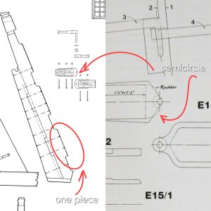
I also asked myself this question, but the anatomy of the Victory and Alert clearly shows that the leading edge of the Alert was not separate from the rudder, but one piece. In the picture on the left. But unfortunately, except for the top view of the hinges, there is no section of the rudder itself. But on the Victory you can see that the rudder was rounded, not beveled. But the hinges were just beveled, like the sternpost. In my case, I implemented this closer to the rounding, but with a small protrusion in the middle. Here, I will most likely do the same. At this scale, it will not be clearly visible and can be interpreted both as rounding and as beveled. To guess for sure.:cool:

20250711_223100.jpg


And again a little poetry in the feed...

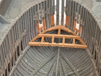
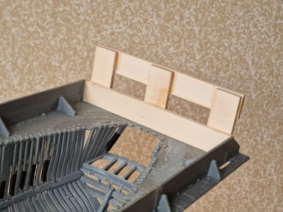
I have been racking my brains for several weeks now on how to implement the railing posts. It is very difficult to explain what exactly I want, but even before yesterday I wanted to pause Alert and return to Victory, since I had reached a dead end. But today I spent about 5 hours doing calculations and finally came up with an idea with posts (toptimbers). On Monday I hope to be able to start implementing these ideas.

20250711_215231.jpg

I will first try to do everything on the second hull and then decide whether to repeat on the first (although maybe I will do it as per the instructions with some adjustments).

But still, it was painful when a solution does not come, or a difficult solution comes, the implementation of which is difficult, and when today the epiphany came - I felt relieved.

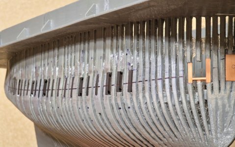
And a few more words about the strength and accuracy of the plastic hull, as a basis for the rough hull. In terms of strength, it is simply like a stone. Rigid and very stable, that is, it will not warp from moisture and the СA glue will not be able to come off it ... well, and precision. For clarity, I put the deck from the first hull into the second and it fit like a glove. Of course, I did not doubt it, but it is still nice to see it.

20250711_173332.jpg
 
Last edited:
Thanks Sergey. The Alert was small so a rudder without a separate bearding piece makes sense, but I would be surprised if it was not a separate piece on Victory. Even on a smaller ship (74 gun of 1780) the contract describes separate pieces.
To be well made, the Pieces tabled to each other, and all but the Main and Bearding Pieces, to be Fir.
It could be both styles were used on different ships. Looking further at some contemporary cutter drawings the forward edge of the rudder/rother is shaded to appear to be rounded as you show. The drawing above in post #422 on the right looks a lot like the one by Goodwin except Goodwin does not show a rounded rudder. In a contract that I found for a 10 gun cutter bearding is called out on the rudder but it does not describe the shape or if there is a separate bearding strip. (The contract is from 1810, well after Alert so may not be at all applicable.) Again, I would be surprised if there were not variations from yard to yard on how they made and shaped the bearding. No matter, I love your build :)
Allan
 
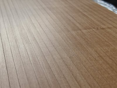
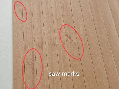
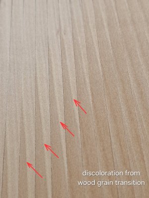
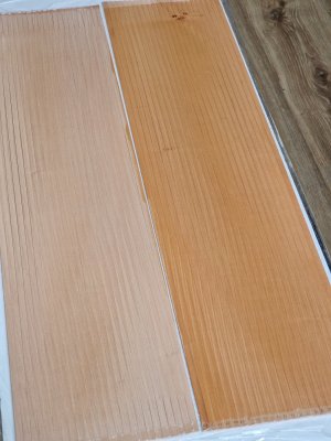
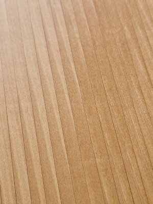
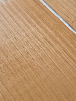
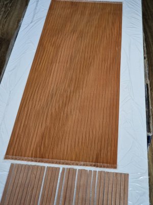
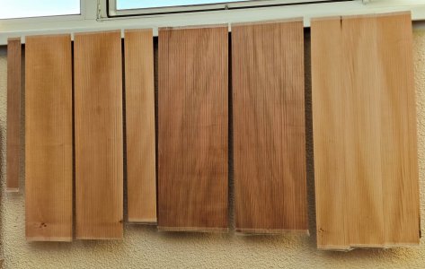
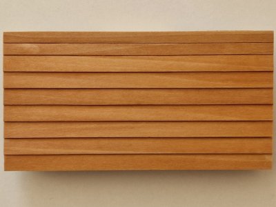
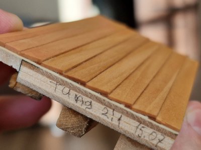
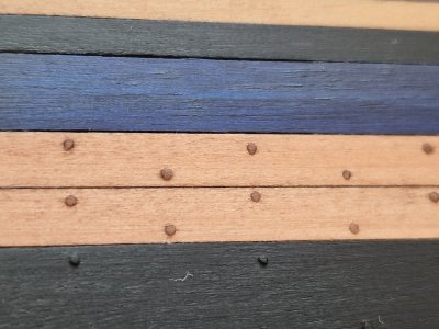
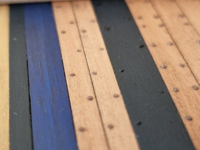
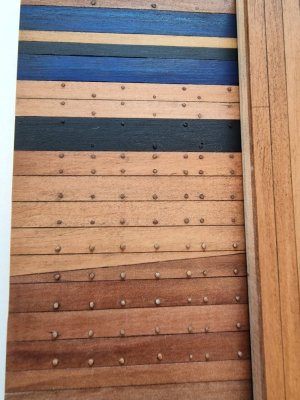
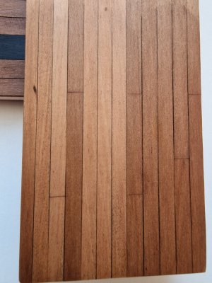
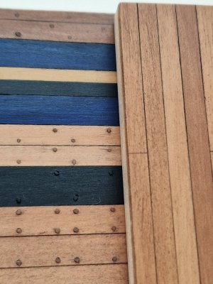
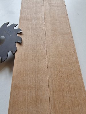
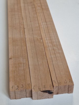
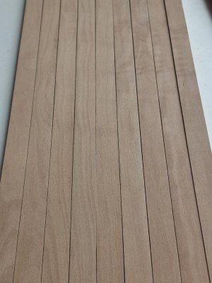
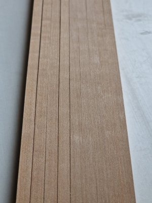
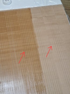
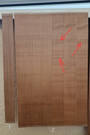
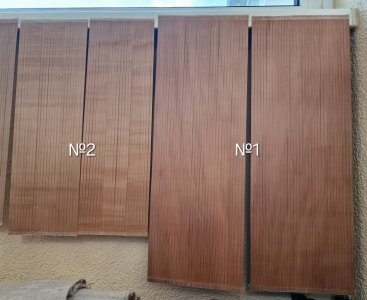
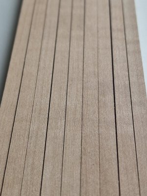
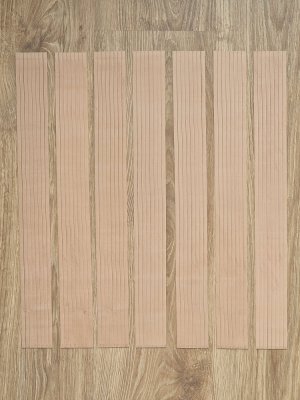
Today I was processing the material for the second building Alert. This is a pear of several shades. And the downside is that I could never find a pear of uniform color. In terms of wood layers, it differs significantly at the transition points. I will talk about this later and show tests.

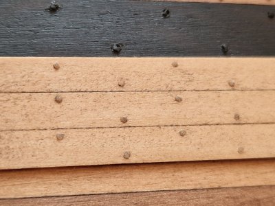
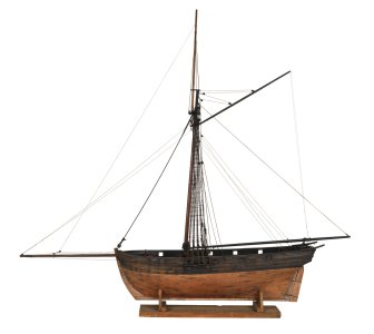
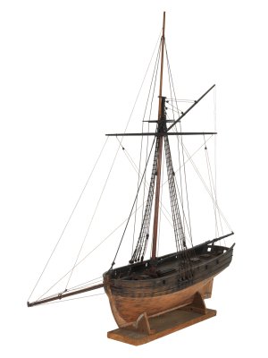
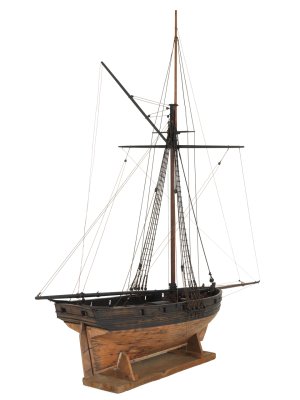
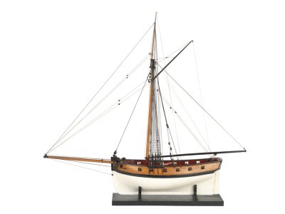
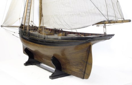
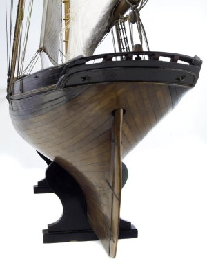
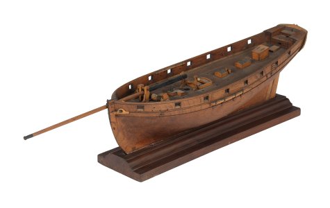
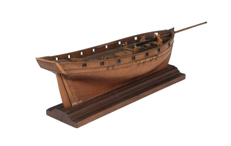
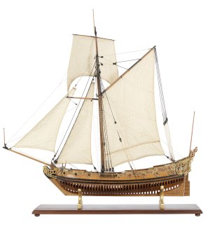
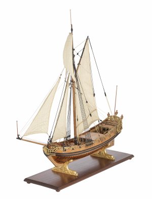
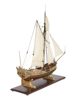
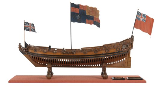
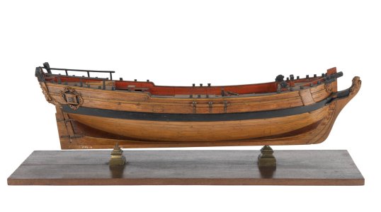
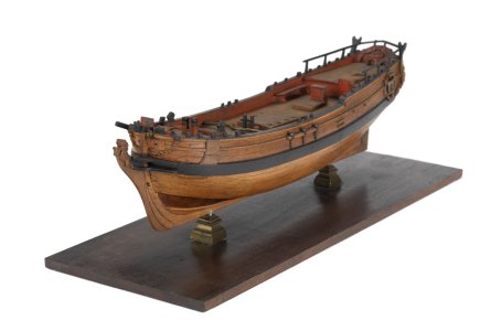
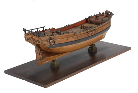
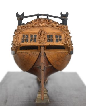
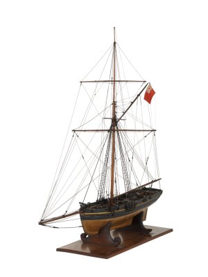
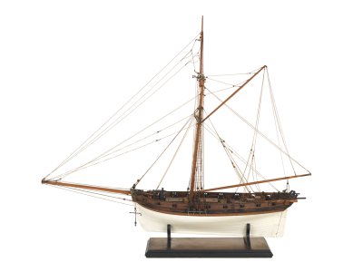
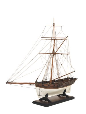
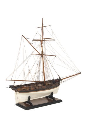
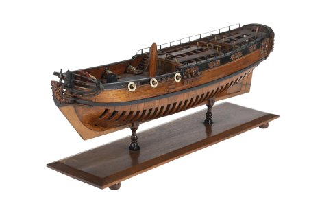
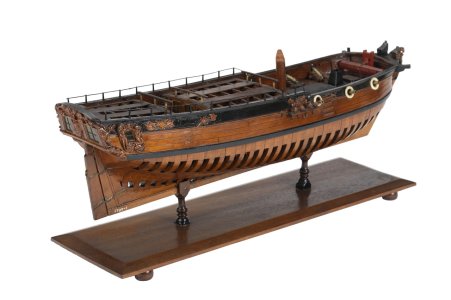
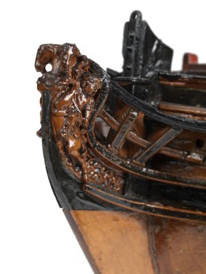
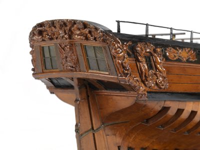
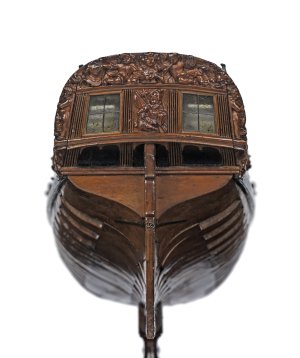
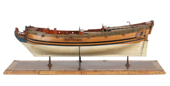
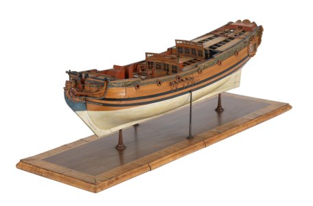
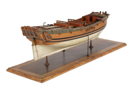
But in parallel, I look through museum specimens to understand how much I shaded this pear with bitumen. Since bitumen can partially hide, or rather camouflage the transitions of pear shades.
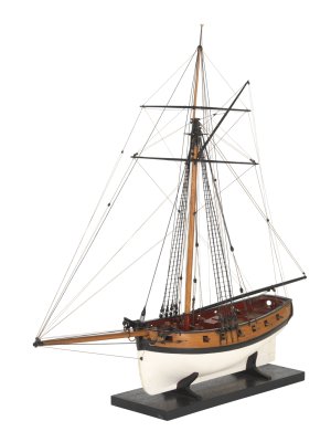
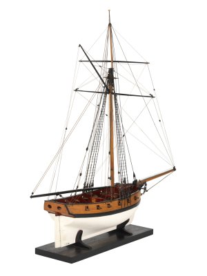
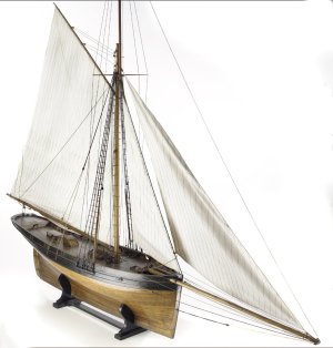
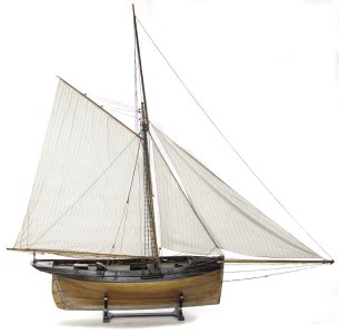
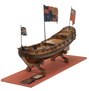
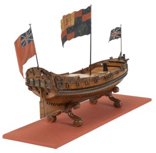
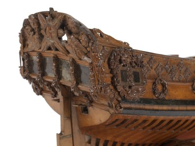
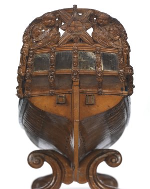
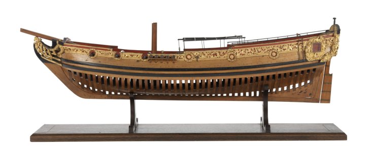
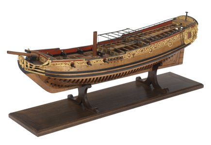
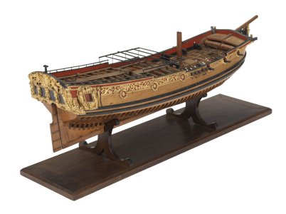
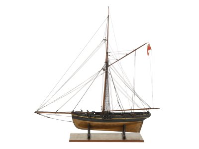
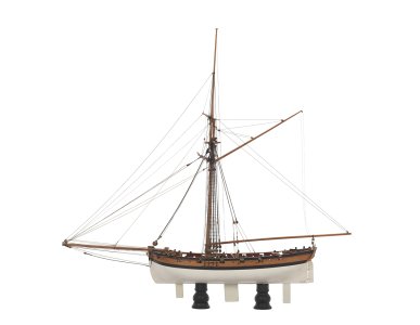
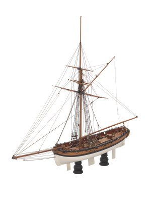
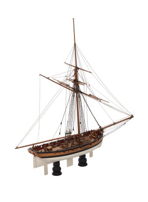
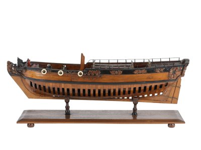
And so I reviewed the entire website of the Greenwich Museum... all 130 pages, 24 exhibits each (by the way, here is a link to GoogleDrive, where I saved all those models that I liked the most, only 470 photos of different ships, different ranks from boats to sailing battleships)...
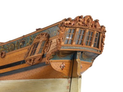
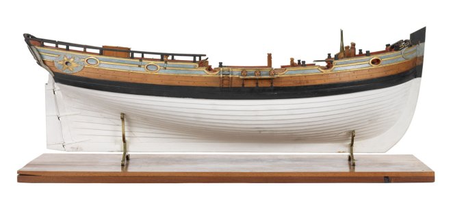
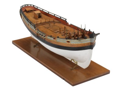
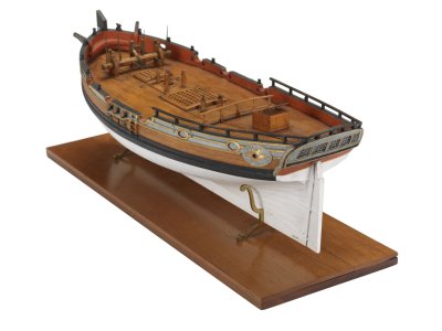
And in two posts I will share models (small ships, cutters) that will be references for me in further visualization of my model. Plus, in the photo you can see the elements of decor, rigging and so on.

1/2


Internet_20250707_011204_5.jpg

Internet_20250707_011204_6.jpg

Internet_20250707_011204_7.jpg

Internet_20250709_014540_2.jpeg

Internet_20250709_014540_3.jpeg

Internet_20250709_014540_4.jpeg

Internet_20250709_015903_1.jpeg

Internet_20250709_015903_2.jpeg

Internet_20250709_015903_3.jpeg

Internet_20250709_015903_4.jpeg

Internet_20250709_214505_1.jpeg

Internet_20250709_214505_2.jpeg

Internet_20250709_214505_3.jpeg

Internet_20250710_000122_1.jpeg

Internet_20250710_000122_2.jpeg

Internet_20250710_000122_3.jpeg

Internet_20250710_152824_1.jpeg

Internet_20250710_152824_2.jpeg

Internet_20250710_152824_3.jpeg

Internet_20250710_152824_4.jpeg

Internet_20250710_152824_5.jpeg

...

Internet_20250709_012524_1.jpeg

Internet_20250709_012524_2.jpeg

Internet_20250709_012524_3.jpeg

Internet_20250709_012524_4.jpeg
 
Please help me understand - are you using actual bitumen - like as in roofing cement and asphalt, or a paint color called "bitumen"?
I use bitumen to simulate the aging effect, this one.
Screenshot_20241106_195137_Samsung Internet.jpg
I'll show you the test results later.


THANK YOU VERY MUCH FOR SHARING ALL THESE BEAUTIFUL PHOTOS. Did you find these doing a search on the RMG Collections website (https://www.rmg.co.uk/collections) or in some other way?
Thanks again!
Allan
Yes, that's right, from this site. Afterwards I gave a link to download 470 photos of models that I liked.
 
Last edited:
Bitumen of Judea appears to be something not easily available in the US. There are acrylic paints the color of bitumen, but that's all they are - paints. All the sources I could find were European.
 
Bitumen of Judea appears to be something not easily available in the US. There are acrylic paints the color of bitumen, but that's all they are - paints. All the sources I could find were European.
That's right, Russ. Its sale is controlled here in the US (you know...everything now causes cancer). Some places won't even ship to the US. I found this place: https://www.napkinshop.co.uk/shop/d...art-liquid-patina-30ml-bitumen-for-antiquing/

It's based on the real thing but has added solvents for use in decoupage. I used it to tint rigging ropes on my Vasa. You can cut it with turpentine or mineral spirits - just don't spill it on your hardwood floors ROTF.

If I recall the cost to ship was predictably offensive. I bought a bunch and then sold off the extras to other modelers just to help pass the test of common sense.

Sorry for the diversion, Sergey!
I don't know about the Judea patina, but the one that I use Idea Patina 710 in Ukraine is available without problems, $5-7. I didn't use another, then I can't say anything about others. And about this, soon there will be the first tests, but not final. You need to be able to work with bitumen. And it's hard. I will try very hard, but I really hope that my results will be good.
 
Today I thought that I would show the first experiments and work on preparing pears for cladding, but no...
Today, the whole day made miscalculations and devices for applying KWL (waterline) on the ship.
To be honest, it's very tiring. It's one thing to do everything according to the instructions from the kit, and the second is to calculate and reinvent the wheel... well ok.

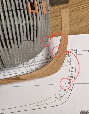
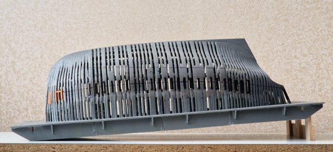
So, to apply a waterline, you need to know the two starting points, front and back. In front, starting from the drawings, I transferred it using a temporary keel...

Alert 1064.jpg

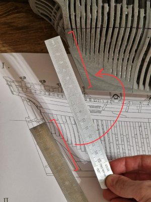
At the back, I just measured with a ruler in a straight line between two points.

Alert 1065.jpg

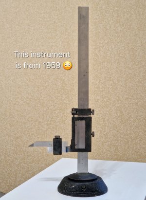
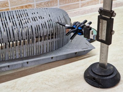
Then I had to create a frame to fix the angle of inclination of the case. To do this, I used this tool...

Alert 1066.jpg

... who is more years old than my father... This is "Stangenreismas" made in the country in which I was born and which no longer exists (praise to the gods). I bought it for $25.
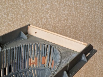
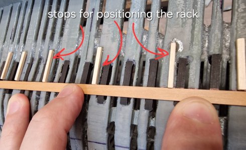
So, using this tool, I lifted the back of the case so that the points of the waterline at the back and front were at the same height. To do this, I glued wooden slats on the front...

Alert 1067.jpg

... first one rack, as a base, and the second glued to it when the front of the ship was exactly at the desired height. I just passively put this rail on the table and it fixed the desired height.

I propped up the back with dumbbell pancakes and similarly glued the base rail, and then 3 supports to it and passively the bottom rail, fixing the height.

Alert 1068.jpg

There is not much beauty in this, but it accurately and reliably holds the desired angle.

Alert 1069.jpg

When everything was ready, I attached a marker to the device and drew a waterline.

Alert 1070.jpg

This is not the final application of KWL, but rather an introductory one, since when lining with slats, the waterline will be cut out with a scalpel, but more on this later.

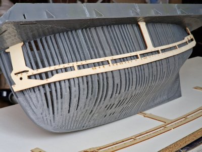
Well, so... overall, I'm pleased. I noticed that the conductor, to transfer the cut line of the hull - not symmetrical. I thought the waterline was not applied correctly. But I checked and could not understand why my eye was not satisfied.. But it turns out that the lines from the conductors on the right and left are not the same everywhere...

THEREFORE, the recommendation to all those who will assemble this model is to use one conductor on both sides! You just need to redraw the notes on the back. And if you make everything with one conductor, then the lines on the two sides will be the same. (I'm talking about this conductor, photo below, I have already shown it before).

Alert 912.jpg

Well, here is the result of today... modest, but it just took a lot of time... and all in order to achieve symmetry.

Alert 1071.jpg

Alert 1072.jpg

Alert 1073.jpg

Alert 1074.jpg

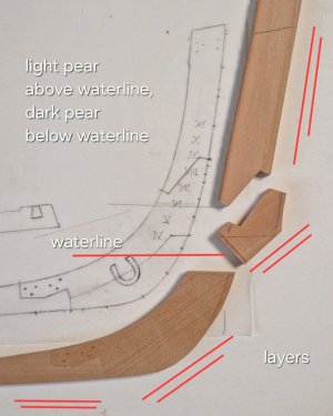
Then I will still try to show you my experiments with oil, bitumen and preparation of rails for cladding, and I will start making a keel for the second case... it will be two-tone at the waterline, like an afterstock and a rudder.

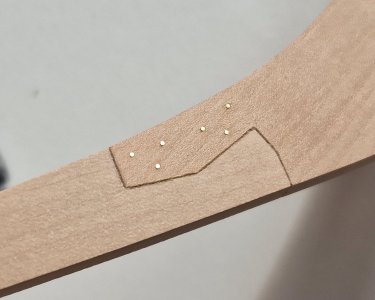
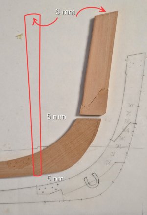
I refused black (above, above the waterline on the keel and steering wheel). There will be two colors, the same as the skin. Above - a light pear, below - dark. Why gave up black... Firstly, I don't really like it and the Latin numbers of the ship's draft will not be visible on black. Plus, the top of the keel, where the main post is fixed, will be for the national team, but more on that later...
 
Last edited:
Today I thought that I would show the first experiments and work on preparing pears for cladding, but no...
Today, the whole day made miscalculations and devices for applying KWL (waterline) on the ship.
To be honest, it's very tiring. It's one thing to do everything according to the instructions from the kit, and the second is to calculate and reinvent the wheel... well ok.

So, to apply a waterline, you need to know the two starting points, front and back. In front, starting from the drawings, I transferred it using a temporary keel...

View attachment 532433

At the back, I just measured with a ruler in a straight line between two points.

View attachment 532434

Then I had to create a frame to fix the angle of inclination of the case. To do this, I used this tool...

View attachment 532435

... who is more years old than my father... This is "Stangenreismas" made in the country in which I was born and which no longer exists (praise to the gods). I bought it for $25.
So, using this tool, I lifted the back of the case so that the points of the waterline at the back and front were at the same height. To do this, I glued wooden slats on the front...

View attachment 532445

... first one rack, as a base, and the second glued to it when the front of the ship was exactly at the desired height. I just passively put this rail on the table and it fixed the desired height.

I propped up the back with dumbbell pancakes and similarly glued the base rail, and then 3 supports to it and passively the bottom rail, fixing the height.

View attachment 532446

There is not much beauty in this, but it accurately and reliably holds the desired angle.

View attachment 532447

When everything was ready, I attached a marker to the device and drew a waterline.

View attachment 532448

This is not the final application of KWL, but rather an introductory one, since when lining with slats, the waterline will be cut out with a scalpel, but more on this later.

Well, so... overall, I'm pleased. I noticed that the conductor, to transfer the cut line of the hull - not symmetrical. I thought the waterline was not applied correctly. But I checked and could not understand why my eye was not satisfied.. But it turns out that the lines from the conductors on the right and left are not the same everywhere...

THEREFORE, the recommendation to all those who will assemble this model is to use one conductor on both sides! You just need to redraw the notes on the back. And if you make everything with one conductor, then the lines on the two sides will be the same. (I'm talking about this conductor, photo below, I have already shown it before).

View attachment 532449

Well, here is the result of today... modest, but it just took a lot of time... and all in order to achieve symmetry.

View attachment 532451

View attachment 532452

View attachment 532453

View attachment 532454

Then I will still try to show you my experiments with oil, bitumen and preparation of rails for cladding, and I will start making a keel for the second case... it will be two-tone at the waterline, like an afterstock and a rudder.

I refused black (above, above the waterline on the keel and steering wheel). There will be two colors, the same as the skin. Above - a light pear, below - dark. Why gave up black... Firstly, I don't really like it and the Latin numbers of the ship's draft will not be visible on black. Plus, the top of the keel, where the main post is fixed, will be for the national team, but more on that later...
I have to restrain myself from attacking this beautiful, flat waterline with a Japanese saw...;)
Nicely laid out, Sergey.:)
Regards, Peter
 
Back
Top