Thank you. Yes, I agree, it should look great under the final layer of oil. The main thing is to nail it well. And don't forget about the bitumen. I hope the bitumen will bring the appearance closer to the museum style.Great work! will look great when oiling is finished!
-

Win a Free Custom Engraved Brass Coin!!!
As a way to introduce our brass coins to the community, we will raffle off a free coin during the month of August. Follow link ABOVE for instructions for entering.
-

PRE-ORDER SHIPS IN SCALE TODAY!
The beloved Ships in Scale Magazine is back and charting a new course for 2026!
Discover new skills, new techniques, and new inspirations in every issue.
NOTE THAT OUR FIRST ISSUE WILL BE JAN/FEB 2026
- Home
- Forums
- Ships of Scale Group Builds and Projects
- HMS Alert 1777 1:48 PoF Group Build
- HMS Alert 1777 1:48 Group Build Logs
You are using an out of date browser. It may not display this or other websites correctly.
You should upgrade or use an alternative browser.
You should upgrade or use an alternative browser.
HMS Alert [1777] 1:48 POF by serikoff. (Two hulls: skeleton and fully rigged)
Today I switched from hull planking to preparing deck material.
Things were really bad with that! Spoiler alert: they were! ...but I think I solved it (but I'm not sure).
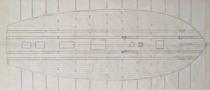
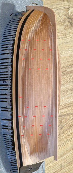
So, first things first. Initially, I wanted to make the deck out of two colors of pear wood. The main color is a light pear wood, like the one on the hull above the waterline, and in the locations shown in the photo below, four pear wood slats in a darker color. Here's a diagram of their positions (the diagram is still in progress).
I previously showed samples with oil and bitumen coating here: Bitum
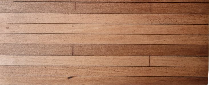
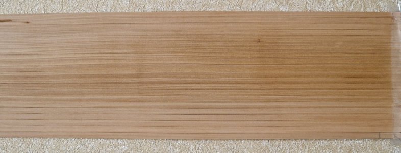
... but I ran into a problem: all my light pear turned out to be striped and I barely had enough for the hull above the waterline, and the one I had prepared for the deck all went into the trash... This is what it looked like:
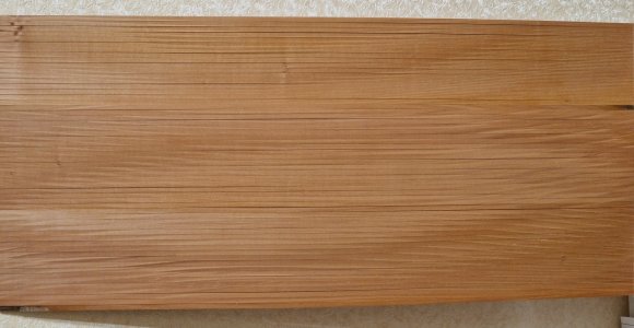
I spent months searching... and words can't describe the level of despair... when every time you order, you see something that's categorically not right for you... And it's not that I'm overly picky, but I think you can see that the pear is striped...
I waited and hoped for a long time... and recently a colleague sent me another pear sample, and it also turned out to be striped...
I even created a forum thread asking for help finding a pear, and many people tried to help. Even a kind man from Poland responded... and believe it or not, he sent me samples: pear, apple, white hornbeam, and even ebony!
His name is @-Waldemar- , and I only paid for the shipping, but he simply gave me the materials. In return, he asked me to tell him honestly about these samples, as he, too, was interested in whether anything would work for me and what I could use each sample for even if it didn't.
This is what the package looked like:
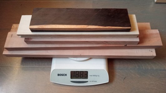
So, I'm fulfilling the request. First, I'd like to thank the kind man again for his responsiveness and say that I really enjoyed trying out all the different types of wood.
Unfortunately, these samples weren't the right color for this particular ship, but! That doesn't mean it was all in vain.
1. I'd never tried apple wood (though I wanted to) and realized it wasn't quite right for me, so this gift saved me from a potential purchase.
2. The pear turned out to be too dark for the deck, but! I use it for other parts, and I liked its dark chocolate color. So, I'm happy with this pear, although unfortunately it didn't solve the deck issue.
3. I really liked the ebony (I've never seen it in real life). But I'd already started making black hornbeam sections on the hull, and they turned out to have slightly different grain, and the black hornbeam actually looks darker. But for some tasks, ebony is very suitable and much better than other woods! I'll talk more about this later, but I'm very happy that I now have it.
4. And the most interesting thing is that I also really wanted light (white) hornbeam! I really liked the grain and color and even considered making a deck out of it... but frankly, in the "museum model" concept (which is the style I want to make this model in), white hornbeam doesn't fit the color palette... But I think you'll also appreciate these hornbeam deck samples...
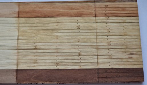
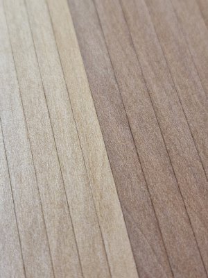
By the way, in the photo: on top is apple (spotted). Below is pear (it turned out very dark, but I like the color). And two shades of white hornbeam. From the middle, the warmer color is higher, and the cooler color is lower (there were two patches in the samples).
Below I'll show how I tried to create deck samples; maybe someone will find it useful. Again, I really liked it, but unfortunately it doesn't fit the concept of my model.
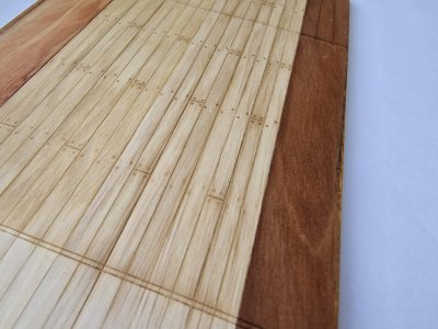
I didn't really like the imitation nailing, but with real dowels it looks very nice.
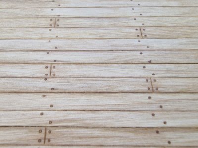
Surprisingly, I liked the hornbeam dowels (on the right, darker) less...
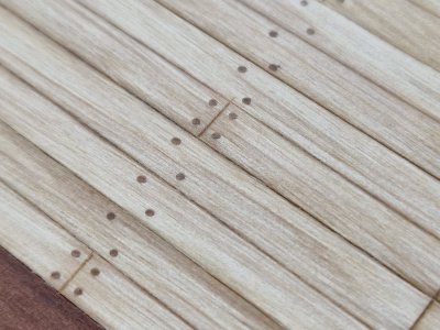
But the ones made from birch toothpicks (they're a bit lighter) look better, in my opinion. See the photo below.
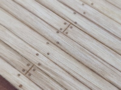
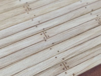
And as they say – here's the result! What I finally arrived at.
I decided (partly due to a lack of alternatives) to use the pear I originally intended to use for the deck's weight boards. Now, it will fill all the space except for the four weight boards (which I'll be making from a different pear).
Here's a spoiler of what the deck will likely look like (without visualizing the weight boards yet, more on that later). For now, I've scattered the boards randomly to test this method. In the original, each board will be matched to its proper place (as on the hull), so that the overall tone is as pure as possible, without streaks or spots.
I coated the sample with Danish oil to prevent the punching bag from darkening as much as with Tung oil.
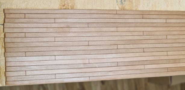
I coated the bottom 6 boards twice with Danish oil, and you can see a slight sheen. I did this to test how both coatings would work under the bitumen.
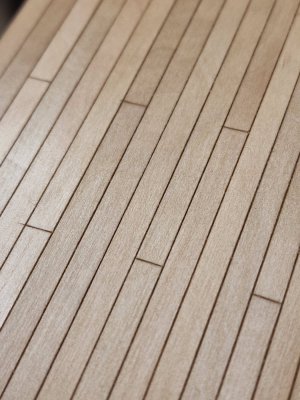
The macro clearly shows the grain and uniformity of the wood, which is exactly what I was looking for and had been searching for for so long. Yes, I would have liked it a little lighter, but on the other hand, maybe it would be even better this way...
Now, about the layout.
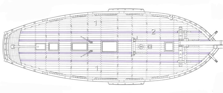
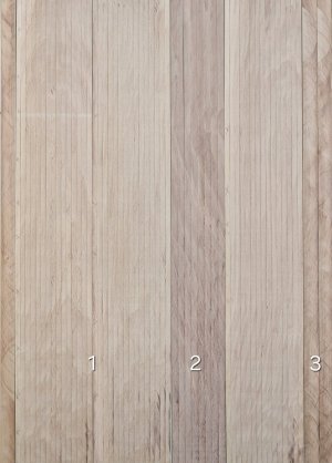
The main deck (1) will be one color of pear (pictured below). The power boards (2) will be a different color. The perimeter boards (3) will be the same color as (1), but they will be made from wide blanks so they can be cut to the desired shape.
After sanding...
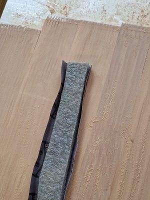
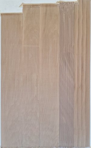
... I covered the entire surface with undiluted Danish oil, using a small piece of paper towel to apply a thin layer and then wiping it dry almost immediately.
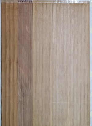
Once the wood had emerged, it was possible to see which fragments would be rejected...
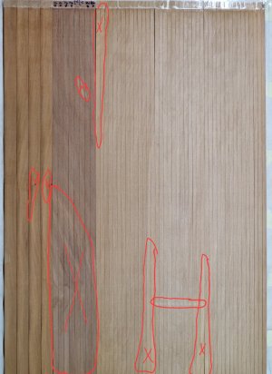
...due to defects, color differences, and other issues. Unfortunately, the darker blanks (which will be used for the deck planks) are only good for half their length. So I'll have to make them prefabricated, assembling the planks on the deck. That's why I cut 8 of these planks instead of 4. Here's how the pear-colored main deck plank and the deck planks will coordinate:
And then, after the oil has dried, I'll calibrate the deck planks for width (they're wider than needed here). Then I'll sort out all the defective parts and assemble all the suitable planks into one finished deck plank to see how it will look on the model. And if I'm satisfied with everything, I can breathe a sigh of relief and continue working on the hull. Meanwhile, the deck will await its fate.
I understand that this topic isn't as interesting as the finished photos of the models, but the importance of this process is invaluable. And to achieve the expected, attractive result, you need to put in the effort and check everything many times. I also don't like all these tests, samples, and experiments, and it annoys me that it takes so much time... but how can this protect me from failure? It convinces me to do more and more of the same tests, samples, and experiments.

Things were really bad with that! Spoiler alert: they were! ...but I think I solved it (but I'm not sure).
So, first things first. Initially, I wanted to make the deck out of two colors of pear wood. The main color is a light pear wood, like the one on the hull above the waterline, and in the locations shown in the photo below, four pear wood slats in a darker color. Here's a diagram of their positions (the diagram is still in progress).

I previously showed samples with oil and bitumen coating here: Bitum

... but I ran into a problem: all my light pear turned out to be striped and I barely had enough for the hull above the waterline, and the one I had prepared for the deck all went into the trash... This is what it looked like:

I spent months searching... and words can't describe the level of despair... when every time you order, you see something that's categorically not right for you... And it's not that I'm overly picky, but I think you can see that the pear is striped...
I waited and hoped for a long time... and recently a colleague sent me another pear sample, and it also turned out to be striped...

I even created a forum thread asking for help finding a pear, and many people tried to help. Even a kind man from Poland responded... and believe it or not, he sent me samples: pear, apple, white hornbeam, and even ebony!
His name is @-Waldemar- , and I only paid for the shipping, but he simply gave me the materials. In return, he asked me to tell him honestly about these samples, as he, too, was interested in whether anything would work for me and what I could use each sample for even if it didn't.
This is what the package looked like:

So, I'm fulfilling the request. First, I'd like to thank the kind man again for his responsiveness and say that I really enjoyed trying out all the different types of wood.
Unfortunately, these samples weren't the right color for this particular ship, but! That doesn't mean it was all in vain.
1. I'd never tried apple wood (though I wanted to) and realized it wasn't quite right for me, so this gift saved me from a potential purchase.
2. The pear turned out to be too dark for the deck, but! I use it for other parts, and I liked its dark chocolate color. So, I'm happy with this pear, although unfortunately it didn't solve the deck issue.
3. I really liked the ebony (I've never seen it in real life). But I'd already started making black hornbeam sections on the hull, and they turned out to have slightly different grain, and the black hornbeam actually looks darker. But for some tasks, ebony is very suitable and much better than other woods! I'll talk more about this later, but I'm very happy that I now have it.
4. And the most interesting thing is that I also really wanted light (white) hornbeam! I really liked the grain and color and even considered making a deck out of it... but frankly, in the "museum model" concept (which is the style I want to make this model in), white hornbeam doesn't fit the color palette... But I think you'll also appreciate these hornbeam deck samples...

By the way, in the photo: on top is apple (spotted). Below is pear (it turned out very dark, but I like the color). And two shades of white hornbeam. From the middle, the warmer color is higher, and the cooler color is lower (there were two patches in the samples).
Below I'll show how I tried to create deck samples; maybe someone will find it useful. Again, I really liked it, but unfortunately it doesn't fit the concept of my model.

I didn't really like the imitation nailing, but with real dowels it looks very nice.

Surprisingly, I liked the hornbeam dowels (on the right, darker) less...

But the ones made from birch toothpicks (they're a bit lighter) look better, in my opinion. See the photo below.


And as they say – here's the result! What I finally arrived at.
I decided (partly due to a lack of alternatives) to use the pear I originally intended to use for the deck's weight boards. Now, it will fill all the space except for the four weight boards (which I'll be making from a different pear).
Here's a spoiler of what the deck will likely look like (without visualizing the weight boards yet, more on that later). For now, I've scattered the boards randomly to test this method. In the original, each board will be matched to its proper place (as on the hull), so that the overall tone is as pure as possible, without streaks or spots.
I coated the sample with Danish oil to prevent the punching bag from darkening as much as with Tung oil.

I coated the bottom 6 boards twice with Danish oil, and you can see a slight sheen. I did this to test how both coatings would work under the bitumen.

The macro clearly shows the grain and uniformity of the wood, which is exactly what I was looking for and had been searching for for so long. Yes, I would have liked it a little lighter, but on the other hand, maybe it would be even better this way...
Now, about the layout.

The main deck (1) will be one color of pear (pictured below). The power boards (2) will be a different color. The perimeter boards (3) will be the same color as (1), but they will be made from wide blanks so they can be cut to the desired shape.

After sanding...


... I covered the entire surface with undiluted Danish oil, using a small piece of paper towel to apply a thin layer and then wiping it dry almost immediately.

Once the wood had emerged, it was possible to see which fragments would be rejected...

...due to defects, color differences, and other issues. Unfortunately, the darker blanks (which will be used for the deck planks) are only good for half their length. So I'll have to make them prefabricated, assembling the planks on the deck. That's why I cut 8 of these planks instead of 4. Here's how the pear-colored main deck plank and the deck planks will coordinate:

And then, after the oil has dried, I'll calibrate the deck planks for width (they're wider than needed here). Then I'll sort out all the defective parts and assemble all the suitable planks into one finished deck plank to see how it will look on the model. And if I'm satisfied with everything, I can breathe a sigh of relief and continue working on the hull. Meanwhile, the deck will await its fate.
I understand that this topic isn't as interesting as the finished photos of the models, but the importance of this process is invaluable. And to achieve the expected, attractive result, you need to put in the effort and check everything many times. I also don't like all these tests, samples, and experiments, and it annoys me that it takes so much time... but how can this protect me from failure? It convinces me to do more and more of the same tests, samples, and experiments.
Last edited:
Thank you very much for sharing some of the testing you do prior to selecting materials for your project. Even though you don't think it's as interesting as the pictures of construction, I found it interesting and your explanation valuable. 
Thank you again for sharing !
Thank you again for sharing !
- Joined
- Sep 10, 2024
- Messages
- 1,022
- Points
- 393

I understand that this topic isn't as interesting as the finished photos of the models, but the importance of this process is invaluable.
On the contrary, the depth to which you go into detail is fascinating as well as inspiring. As you have already shown, the outcome will be well worth the trouble!
I do have one question, however, and I believe it may be a translation or slang issue. What exactly do you mean by "punching bag"? In the USA it is...;

... but somehow I can't visualize that on your ship!

Thank you! I'm so glad you found this information interesting. As they say, "the devil is in the details," so it's important to work on all those little details. Today, the results of all your efforts will be revealed...Thank you very much for sharing some of the testing you do prior to selecting materials for your project. Even though you don't think it's as interesting as the pictures of construction, I found it interesting and your explanation valuable.
Thank you again for sharing !
Definitely! It's very difficult to find good non-bamboo toothpicks. Bamboo toothpicks leave a porous end that looks out of place, so it's best not to use bamboo toothpicks, which I think you already know.Toothpicks made of wood are a very scarce and unavailable commodity. European Union wants to kill off modelers. These bamboo ones are everywhere
Thank you very much. I'll continue to post my experiments. And regarding the translation... yes, sometimes there are translation difficulties, and the translator misspelled something that I can't always verify.On the contrary, the depth to which you go into detail is fascinating as well as inspiring. As you have already shown, the outcome will be well worth the trouble!
I do have one question, however, and I believe it may be a translation or slang issue. What exactly do you mean by "punching bag"? In the USA it is...;
View attachment 549035
... but somehow I can't visualize that on your ship!
Our word "pear" is spelled and pronounced the same and can refer to both the fruit (a type of wood) and a punching bag. That's why the translator translated the second version.

I'll edit it now))
A big advantage of Danish oil is that it dries very quickly and doesn't stink like tung oil or, especially, linseed oil. It's a shame that tung oil darkens wood much better, so I can't use Danish oil everywhere. So, after it dried, I selected the best boards from the prepared ones and assembled a deck from them (for now, just as a sample).
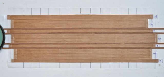
I then cut out the deck profile on paper and covered it to create a visualization of the future deck.
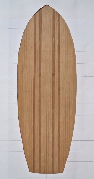
The boards within the section will shift slightly (front to back) and be slightly mixed to avoid a repeatable pattern when sawing. But important! The boards will not rotate (clockwise or counterclockwise). All will face exactly the same direction to avoid shimmering (this is when a single-grain board can have a different color at different angles than one rotated 180 degrees, and even a slightly different sheen, which is not what I want). Looking ahead, I temporarily rotated the dark power boards 180 degrees for ease of installation. In the last photos, the front four dark boards appear darker at a certain angle, even though they are the same section, rotated 180 degrees. I've already written about why the dark boards aren't solid; I simply didn't have a long enough section, so I had to join them.
This is what the macro looks like. Unfortunately, it's cloudy right now, so depending on the distance, the photos turn out completely different colors. But in person, the color is very beautiful.
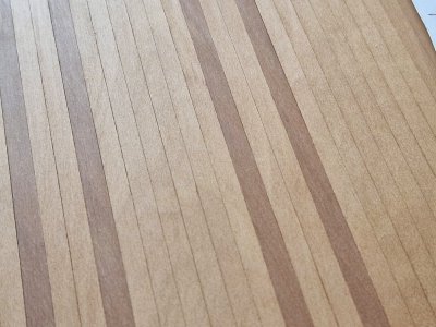
And this is what a comparison of different pear colors looks like (two on the sides and two on the deck).
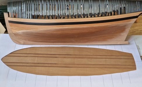
By the way, in the future at least 3-4 other pear colors will be used on this ship...
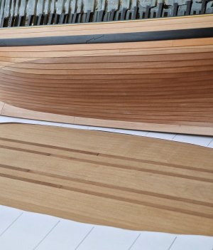
...well, that seems to be the end of the deck issue, and I'm continuing to work on the hull. All the best!

I then cut out the deck profile on paper and covered it to create a visualization of the future deck.

The boards within the section will shift slightly (front to back) and be slightly mixed to avoid a repeatable pattern when sawing. But important! The boards will not rotate (clockwise or counterclockwise). All will face exactly the same direction to avoid shimmering (this is when a single-grain board can have a different color at different angles than one rotated 180 degrees, and even a slightly different sheen, which is not what I want). Looking ahead, I temporarily rotated the dark power boards 180 degrees for ease of installation. In the last photos, the front four dark boards appear darker at a certain angle, even though they are the same section, rotated 180 degrees. I've already written about why the dark boards aren't solid; I simply didn't have a long enough section, so I had to join them.
This is what the macro looks like. Unfortunately, it's cloudy right now, so depending on the distance, the photos turn out completely different colors. But in person, the color is very beautiful.

And this is what a comparison of different pear colors looks like (two on the sides and two on the deck).

By the way, in the future at least 3-4 other pear colors will be used on this ship...

...well, that seems to be the end of the deck issue, and I'm continuing to work on the hull. All the best!
- Joined
- Sep 10, 2024
- Messages
- 1,022
- Points
- 393

The boards will not rotate (clockwise or counterclockwise). All will face exactly the same direction to avoid shimmering (this is when a single-grain board can have a different color at different angles than one rotated 180 degrees, and even a slightly different sheen, which is not what I want)
The technical term for this is "chatoyance". In the furniture industry, we just call it "flip" and is something we have to pay close attention to when selecting veneer plates for pieces, especially table tops. Sometimes plates are alternated intentionally to enhance the appearance, as in a starburst pattern on a round table, but other times it is a distraction and we have to be careful to orient the plates correctly. This is something most modelers don't think about, so my hat is off to you!
Oh, interesting! I'll find out what that's called. Yes, you're right. Sometimes modelers deliberately rotate the boards and alternate them to achieve the maximum effect of color diversity. But sometimes this is appropriate, and sometimes it results in excessive zebra patterns.The technical term for this is "chatoyance". In the furniture industry, we just call it "flip" and is something we have to pay close attention to when selecting veneer plates for pieces, especially table tops. Sometimes plates are alternated intentionally to enhance the appearance, as in a starburst pattern on a round table, but other times it is a distraction and we have to be careful to orient the plates correctly. This is something most modelers don't think about, so my hat is off to you!
So, I've sorted out the deck for now, now let's move on to the hull. First, scrape off any remaining CA glue with a straight blade.
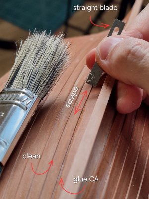
It's a simple process, but very energy-intensive. You constantly need to find the right lighting angle to see the shine of the glue. And every time you think everything is clean, there's glue visible somewhere else.
Before that, I also filled all the gaps between the frames with glue...
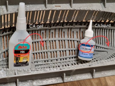
...and I'm pretty sure it's unnecessary, but since I have a lot of glue, I filled the narrow gaps with liquid CA, and basically everything else with CA gel. And I think this will make the hull feel like stone, even though it's already quite rigid.
I've already done one side and immediately decided to mark the doweling locations and the joints so I can show you the whole process.
First, I transfer the frame positions from the first hull to the old, defective keel.
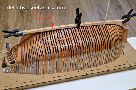
To accurately transfer the lines, I place the strip in the space between the frames (holding it vertically) and trace around it on both sides.
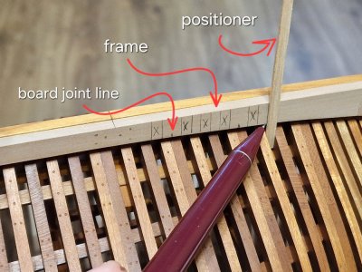
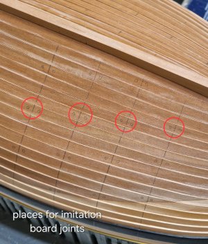
I mark the space between the frames with an X and put a mark in the center of the double frames to mark the joint line between the boards. Nailing will be done in the center of each frame.
For both the front and back, I immediately put a line in the center of the frame:
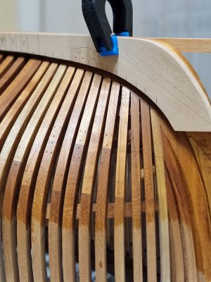
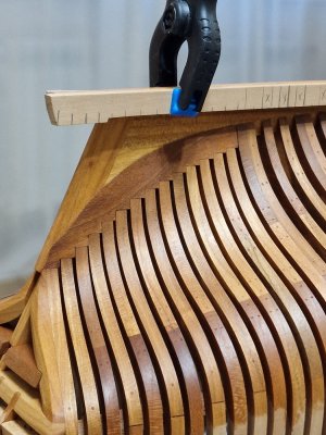
In these sections, everything will be a little different (I'll talk about this later), but for now I will be drawing the joint lines of the boards.
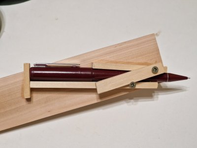
To do this, I created this simple device. I glued stopper strips around the perimeter of the pen to a flat piece of wood, and added a locking mechanism on top to keep the pen firmly in place but still allow it to slide out when needed.
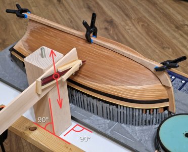
Then I installed a rectangular leg from the future display case (more on that later). Anything with a 90-degree angle can be used. The goal is to ensure that the plane of our pencil slides along the strictly vertical plane of the base, which is strictly perpendicular to our stand.
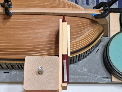
Then I place the tip of the pencil on the mark between the two frames (the center of the double frames) and check from below at the same point (on the plastic)...
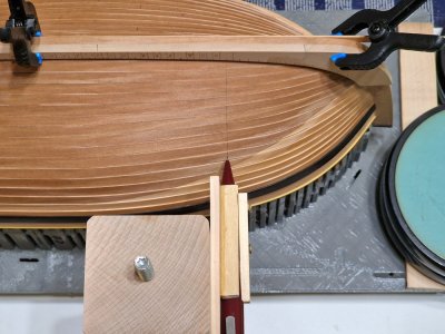
... and I draw a line by sliding the plane of the jig-pencil along the plane of the base.
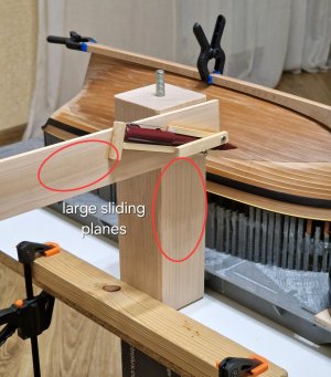
It's important that these surfaces are wide enough to ensure maximum sliding confidence and smoothness (up and down only).
To ensure stability throughout the process, I clamp the frame frame and the base itself with clamps.
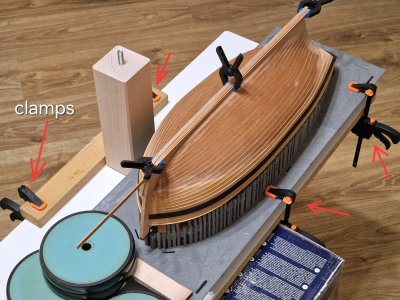
As a result, I get strictly vertical lines along the complex curves of the sheathing.
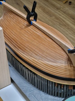
Then I mark with circles the places where I will make the joints of the boards (imitation joints).
Then all the same procedures will be carried out to apply the lines along which the gel coating will be carried out... but more on that later... you first need to finish with all the above procedures.

It's a simple process, but very energy-intensive. You constantly need to find the right lighting angle to see the shine of the glue. And every time you think everything is clean, there's glue visible somewhere else.
Before that, I also filled all the gaps between the frames with glue...

...and I'm pretty sure it's unnecessary, but since I have a lot of glue, I filled the narrow gaps with liquid CA, and basically everything else with CA gel. And I think this will make the hull feel like stone, even though it's already quite rigid.
I've already done one side and immediately decided to mark the doweling locations and the joints so I can show you the whole process.
First, I transfer the frame positions from the first hull to the old, defective keel.

To accurately transfer the lines, I place the strip in the space between the frames (holding it vertically) and trace around it on both sides.

I mark the space between the frames with an X and put a mark in the center of the double frames to mark the joint line between the boards. Nailing will be done in the center of each frame.
For both the front and back, I immediately put a line in the center of the frame:


In these sections, everything will be a little different (I'll talk about this later), but for now I will be drawing the joint lines of the boards.

To do this, I created this simple device. I glued stopper strips around the perimeter of the pen to a flat piece of wood, and added a locking mechanism on top to keep the pen firmly in place but still allow it to slide out when needed.

Then I installed a rectangular leg from the future display case (more on that later). Anything with a 90-degree angle can be used. The goal is to ensure that the plane of our pencil slides along the strictly vertical plane of the base, which is strictly perpendicular to our stand.

Then I place the tip of the pencil on the mark between the two frames (the center of the double frames) and check from below at the same point (on the plastic)...

... and I draw a line by sliding the plane of the jig-pencil along the plane of the base.

It's important that these surfaces are wide enough to ensure maximum sliding confidence and smoothness (up and down only).
To ensure stability throughout the process, I clamp the frame frame and the base itself with clamps.

As a result, I get strictly vertical lines along the complex curves of the sheathing.

Then I mark with circles the places where I will make the joints of the boards (imitation joints).

Then all the same procedures will be carried out to apply the lines along which the gel coating will be carried out... but more on that later... you first need to finish with all the above procedures.
I'm deathly allergic to CA - if I doused it on everything the way you do, I'd be out of commission for weeks and weeks...
How's the finger healing?
How's the finger healing?
- Joined
- Oct 23, 2018
- Messages
- 886
- Points
- 403

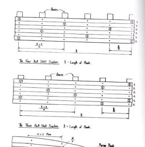
The English shipwrights used the 3-butt of 4-butt shift system for planking. Have a look by Goodwin. He shows a sketch how the planking scheme is correct.Your chosen scheme is not correct.
Wow, I'm so sorry. Allergies are always bad. I've heard about that many times. In my case, it would have simply stopped or even ended my project, since another glue wouldn't have been able to bond the trim to the plastic. I work in a well-ventilated area, try not to inhale the fumes, and activate the glue as quickly as possible so it becomes inert. Thank you so much for the question about the finger! It's almost healed, it doesn't hurt, but it's not completely healed yet. I think in a couple more days everything will be completely healed. Thank you so much.I'm deathly allergic to CA - if I doused it on everything the way you do, I'd be out of commission for weeks and weeks...
How's the finger healing?
Goodwin's anatomy doesn't even have a diagram of a specific item below the wale board! I used a diagram that corresponds to the country and period. Please provide evidence for your point of view so I can offer an alternative. This is the diagram I follow.The English shipwrights used the 3-butt of 4-butt shift system for planking. Have a look by Goodwin. He shows a sketch how the planking scheme is correct.Your chosen scheme is not correct.

This information is from a book
Historic ShipModels
Wolfram zu Mondfeld.
And this applies to all ships of that era. Please provide your source and why you think mine is incorrect.
You might be confused by the fact that there was only one joint, but that's only the front section. There are 2-3 joints, and therefore there are 3 or sometimes 4 boards in a belt, which corresponds to the length of the boards of that era.
Last edited:
My reasons:The English shipwrights used the 3-butt of 4-butt shift system for planking. Have a look by Goodwin. He shows a sketch how the planking scheme is correct.Your chosen scheme is not correct.
Are you sure the pattern you showed doesn't refer to deck planking?
 , let's start from scratch and start from the beginning. The book includes this illustration in the hull planking section.
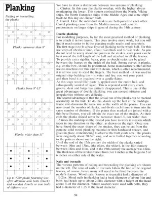
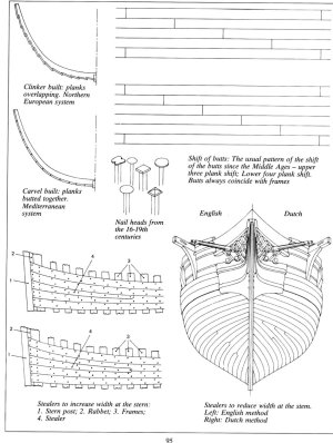
The joints were offset by either 3 or 4 planks, depending on the ship's dimensions. The larger the ship, the more joints, and then the lower option is used. However, if the ship is smaller, an offset of 3 is more than sufficient.
With this layout, the Alert always has two long planks and one slightly shorter one on the hull. The joints are closer together at the front and rear, as it's undesirable to have joints in the middle section due to the loss of strength.
Now let's look at the Deck and its layout:
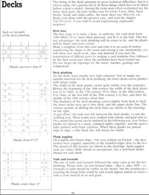
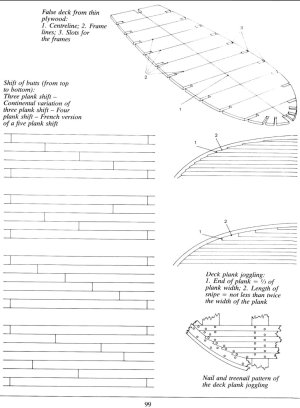
As a conclusion, the offset of 3 or 4 boards applies to both the hull and the deck.
When I was planning the construction, I studied several books, including this one:
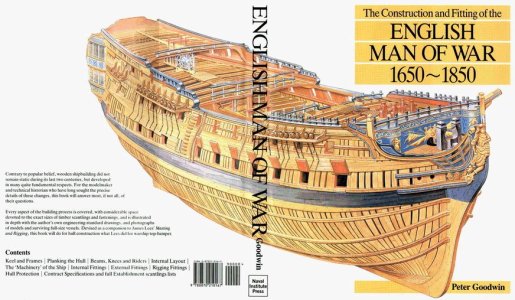
Where everything is described in detail regarding the length and width of the plank and everything else. The length of the plank could be from 18-24 and even 25 to 30 feet, depending on the timber used near the shipyard. In my 1:48 scale and my layout, the maximum length of the plank is 18 cm, which corresponds to 28 feet. There are three planks in the waist, and since Goodwin himself indicated in his anatomy that there were three planks in the waist, this is correct.

Unfortunately, Goodwin's anatomy doesn't mention or illustrate how and where the joints below (where the question mark is) were located. Therefore, if we take all the materials and information from the books as a basis, we arrive at the exact layout I've created.
Last edited:
- Joined
- Oct 23, 2018
- Messages
- 886
- Points
- 403

@AnobiumPunctatum @serikoff
In the 17th century, wood, especially oak, was strategically crucial for the construction of warships. Each nation protected its own resources and supply chains, and exporting wood to a hostile state was an act of national treason.
The key timber import route was the so-called "Baltic route."
Jean-Baptiste Colbert, reforming French economy and navy from the 1660s, utilized timber supplies both from northern countries and directly from Dutch. During the Franco-Dutch War, trade was banned, resulting in massive supply shortages.
French ships were built without any reference to construction plans. To conserve wood, patterns were not used, instead, they were laid as-is, random planks, contrary to the above pattern. This resulted in a drastic decline in the quality of French fleet, exposing the ships to the risk of sinking.
This situation was well-known and described in reports of Colbert and his son, Seignelay, who succeeded him in overseeing French fleet.
How would you respond to this information?
From this it appears that these shifts on planks are simply our modelers invention, and during crisis they were built simply to save wood...
So this is completely consistent with what I did. An offset of 3 or 4 boards is correct. What you indicated applies to thin boards, where two dowels aren't used, but only at the joints. In the clinker version, the boards are joined like this. But the joint pattern remains unchanged: 3 offsets (for this ship) and 4 for larger ships.Sorry, that I wasn't precise enough. I mean: Goodwin "The construction and fitting of the Sailing Man of War, 1650-1850"
Here is the sketch from page 58:
View attachment 549398
I just wanted to clarify that we're talking about exactly the same thing. And as a result of this entire conversation, the layout I've created is correct. But thank you for giving me pause, and I've once again looked at the literature and confirmed its veracity.
And your illustration fits the deck because the planks are nailed to the beams. Just a note.
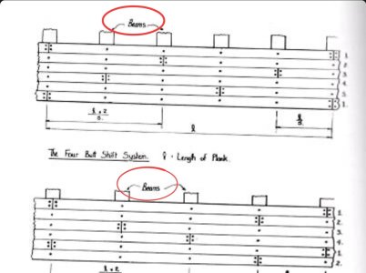
Last edited:
I agree with you in part. We're talking about French ships here. England was famous for its great attention to its navy, which is how it achieved world dominance. Therefore, I'm sure that in key respects, everyone tried to follow the drawings, and where possible, they skimped on wood. It's clear from the Victory that the ship was built without skimping on wood. Yes, smaller ships could have been more economical, but I don't think this was particularly true for warships. As for the model, naturally, we try to make the layout more beautiful, although on mine, due to a shortage of material in some places, I had to make joints in other places, which also corresponds to what you wrote.@AnobiumPunctatum @serikoff
In the 17th century, wood, especially oak, was strategically crucial for the construction of warships. Each nation protected its own resources and supply chains, and exporting wood to a hostile state was an act of national treason.
The key timber import route was the so-called "Baltic route."
Jean-Baptiste Colbert, reforming French economy and navy from the 1660s, utilized timber supplies both from northern countries and directly from Dutch. During the Franco-Dutch War, trade was banned, resulting in massive supply shortages.
French ships were built without any reference to construction plans. To conserve wood, patterns were not used, instead, they were laid as-is, random planks, contrary to the above pattern. This resulted in a drastic decline in the quality of French fleet, exposing the ships to the risk of sinking.
This situation was well-known and described in reports of Colbert and his son, Seignelay, who succeeded him in overseeing French fleet.
How would you respond to this information?
From this it appears that these shifts on planks are simply our modelers invention, and during crisis they were built simply to save wood...


