I think we need the plans in metric system too,imperial measurment confuses the hell out of the Europeans like myself 

-

Win a Free Custom Engraved Brass Coin!!!
As a way to introduce our brass coins to the community, we will raffle off a free coin during the month of August. Follow link ABOVE for instructions for entering.
-

PRE-ORDER SHIPS IN SCALE TODAY!
The beloved Ships in Scale Magazine is back and charting a new course for 2026!
Discover new skills, new techniques, and new inspirations in every issue.
NOTE THAT OUR FIRST ISSUE WILL BE JAN/FEB 2026
- Home
- Forums
- Ships of Scale Group Builds and Projects
- Group Build Archives
- Blandford Cross Section PoF Group Build
You are using an out of date browser. It may not display this or other websites correctly.
You should upgrade or use an alternative browser.
You should upgrade or use an alternative browser.
That's a possibility but converters can be found all over the net, I work with metric and Standard tooling so I have up to 1" 25.4mm locked on my head. With the exception of Machining I use the metric system quite often for measurements and I prefer it especially for model building.
That's a possibility but converters can be found all over the net, I work with metric and Standard tooling so I have up to 1" 25.4mm locked on my head. With the exception of Machining I use the metric system quite often for measurements and I prefer it especially for model building.
converters are not a big help because when you convert from imperial to metric you don't get all the time a round number like 3mm , maybe 3.2mm and that is hard to work with
Valid Point Brother
- Joined
- Oct 19, 2018
- Messages
- 72
- Points
- 113

Ok grazie mille a tutti, ora è abbastanza chiaro anche se ci sono alcuni passaggi che non mi sono chiari come le misure della chiglia che se non sbaglio guardando la tabella mi mostra le seguenti misure (3/8 "X 2" X 10 ") che convertiti nel sistema metrico risulterebbe in mm (9.525 X 50.8 X 254) in scala di 1/32. Grazie in anticipo della gentilezza .
Translated:
thanks a lot to all, now it is quite clear even if there are some steps that are not clear as the measures of the keel that if I'm not mistaken looking at the table shows me the following measures (3/8 "X 2" X 10 ") that converted into the metric system would result in mm (9.525 X 50.8 X 254) in 1/32 scale.Thanks in advance of kindness.
thanks a lot to all, now it is quite clear even if there are some steps that are not clear as the measures of the keel that if I'm not mistaken looking at the table shows me the following measures (3/8 "X 2" X 10 ") that converted into the metric system would result in mm (9.525 X 50.8 X 254) in 1/32 scale.Thanks in advance of kindness.
che e corretto contento che hai risolto
that's correct Glad you got it sorted out
that's correct Glad you got it sorted out
Mike:
I've got an edit to the plans I'd like to suggest. It would really be beneficial if you could note the location of the trim lines on the cross section plans for frames 1 and 9; just as you've done for the deck clamp locations and the top of the frame. Much easier than trying to measure when the frames are installed.
Also, the keelson is square in profile (3/8" X 3/8" for 1:32 scale) in the BOM, but measures 3/8" wide by 5/16" tall on the plans. Build to the plans or BOM? I suppose it doesn't matter much, since the only thing the keelson height really affects is the pillar height!
Thanks Mike, I am going to attempt to do a lot of the work on my CNC so it will all be experimental. I will save all the GCode and will make it available to members of this build that have CNC's.
I was just looking through this feed trying to determine if CNC would be a good way to go with this build, I don't have a ton of space to cut all the pieces with the various machines needed. Have you had success with the CNC machine? I saw another thread where the person was building a wonderful battle station with CNC and it looked crisp and excellent.
There is an error on the BOM for part 3 of the 1:32 scale plans. When framing the hold, there are two different sized footwaling planks. Both are 3/64" thick. 6 pieces are 1/4" wide, and 10 pieces are 3/16" wide. The BOM lists them as 3/32" wide, not 3/16".
Mike Shanks, Don Robinson and I are building the battle station! We used a combination of laser and CNC to cut out all the parts. It worked well. CNC would definitely work well for the Blandford cross section!
Mike Shanks, Don Robinson and I are building the battle station! We used a combination of laser and CNC to cut out all the parts. It worked well. CNC would definitely work well for the Blandford cross section!
I was just looking through this feed trying to determine if CNC would be a good way to go with this build, I don't have a ton of space to cut all the pieces with the various machines needed. Have you had success with the CNC machine? I saw another thread where the person was building a wonderful battle station with CNC and it looked crisp and excellent.
There are a couple of ways one could cut out with a CNC, obviously all the parts for the various frames and secondly, the complete frame. If one chooses to cut the complete frame (in 1/2 inch thick) the grain of the wood must be taken into account, a close grain wood would be ideal. If the frames were cut out in 1/4 inch wood then a softer wood (like pine) can be used but cross the grain of the two pieces, as in laminated boards.
Although CNC's are great for cutting out fast and accurately, the most time consuming parts is turning it into a decent drawing that can then be turned into code, to give you an idea: the original drawings are in PDF, my program accepts those drawings. When they are zoomed in the solid line becomes a double line, double layer of rectangular boxes with a diagonal line through them, I drew the new line on the outside, turns out they are all slightly bigger, won't be a problem.
By the way frames 1 - 5 are identical!! realized that halfway through redoing frame 4!
When the code has been tweaked I will be happy to share it, I will put a notification in this build log.
To the moderators, thanks for organizing the Spell check type option.
A CNC with a table of about 24 x 36 (or up to) would suffice for this project.
FOR PICTURES DESCRIBING THE BASIC WORK IN THE ABOVE POST #213 PLEASE REFER TO MY BLANDFORD BUILD LOG https://shipsofscale.com/sosforums/index.php?threads/erics-blandford-build.2384/
Mike: In a real ship the keelson would be bolted to the frames/keel with metal bolts. What would be the spacing? One per frame? Two per frame? I have some
model railroad track spikes with heads about 2-1/2 scale inches in diameter I'd like to add.
model railroad track spikes with heads about 2-1/2 scale inches in diameter I'd like to add.
1 per frame Doc right down the center. and the bolts were square topped with washer if it going to be seen I would mill a hair off the spike to make it square at the top and the rest would look like the washer.
I think we need the plans in metric system too,imperial measurment confuses the hell out of the Europeans like myself
...imperial measurements confuse the hell out of the
Thanks, Joe!
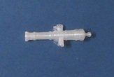
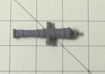
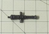
I have not started my build yet but have downloaded the plans material and have been checking it out. I've also been reading all of the great build logs. I was especially interested in the comments in this post regarding Cannons. I have a lathe but am not sure that I can turn two Cannons that are duplicates. I do have a 3D Printer and investigated 3D Cannons. I found a number of objects that are already developed and free to use. I've attached a Cannon that I printed off that took be approximately 30 minutes to print. It took less than a meter of filament to print it. Cannon 1 is as it came off of the printer. Cannon 2 is as it was after I cleaned it up and sprayed it with primer. Cannon 3 is after I coated it with a medal simulating coating that I got at Michaels and Cannon 4 is after I painted it with a coat of flat black.
When I get started on my build I will probably use this as my Cannons.
When I get started on my build I will probably use this as my Cannons.
WOW. That’s really nice.
I have not started my build yet but have downloaded the plans material and have been checking it out. I've also been reading all of the great build logs. I was especially interested in the comments in this post regarding Cannons. I have a lathe but am not sure that I can turn two Cannons that are duplicates. I do have a 3D Printer and investigated 3D Cannons. I found a number of objects that are already developed and free to use. I've attached a Cannon that I printed off that took be approximately 30 minutes to print. It took less than a meter of filament to print it. Cannon 1 is as it came off of the printer. Cannon 2 is as it was after I cleaned it up and sprayed it with primer. Cannon 3 is after I coated it with a medal simulating coating that I got at Michaels and Cannon 4 is after I painted it with a coat of flat black.
When I get started on my build I will probably use this as my Cannons.
And where can I find the files to print?
Here are three files that are available. There are others also you just have to search on Thingiverse.com. The cannon I showed is the first one. I have also printed the wheels from the third file to use whenever I get to that part of the build.And where can I find the files to print?
https://www.thingiverse.com/thing:2751406
https://www.thingiverse.com/thing:2669499
https://cults3d.com/en/3d-model/game/naval-cannon
Bill


