HMS Fly Build (Amati) 1:64 by Nomad

I used the intermission between the hull and rigging efforts to assemble a small lifeboat that came with the Fly's upgrade kit. The hull was a metal affair and various lengths and shades of wood made up the bottom boards, thwarts and sternsheets.

View attachment 427311

The oars were decorated as per instructions, brown handles (rope in this instance), white shafts, and alluring copper guards for the tips.

View attachment 427312

A single kedge anchor and four boarding pikes, also painted to specification to emulate wooden shafts and iron tips.

View attachment 427313

The oars and pikes are bundled together, and, along with the anchor, bundled aboard and secured in the lifeboat.

View attachment 427314

The lifeboat will ulimately be lashed to a pair of spare topmasts and suspended in the open air above the waist. This is likely to interfere with the rigging at this stage and will be installed later on. Probably much, much later on, given the current level of my rigging skills and expertise ROTF

View attachment 427315

Thanks for checking in :)

Mark
A very nice long boat with a lot of nice details. Well done, Mark.
Regards, Peter
 
Hi @Nomad, well my build is underway, enjoying it but things move slow as I figure out tools and method. Thanks again for your great thread here. It is invaluable to me. I’m using a Shelly’s wood glue that was in the garage. Seems to work fine but wondering if you have a brand you’d recomend? have you ever used something like liquid nails for an extra strong bond?

IMG_3875.jpeg
 
I’m using a Shelly’s wood glue that was in the garage. Seems to work fine but wondering if you have a brand you’d recomend? have you ever used something like liquid nails for an extra strong bond?
Rob, I must admit that I have only ever used two glues in my ship modelling to date: Gorilla (PVA) Wood Glue and Gorilla (CA) Super Glue. Both have served me well and I haven't had any real need to try anything else so far. The PVA is very strong and is more than sufficient to hold your hull and planking together very well. It can be undone however, if necessary, by applying steam to the bond. The CA is less easy to reverse as I imagine most CA glues are. My only caution is not to use the CA on any of your black rope rigging as it tends to dry in an off-white colour that does not look attractive and is not easy to remove.
 
Last edited:
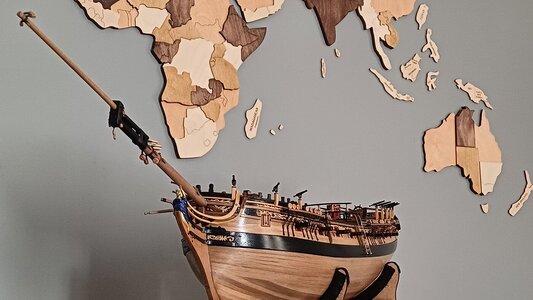
Onwards and upwards. The masts and spars are next, and the bowsprit was as good a spar as any to begin with. After a quick review of the plans I realised the enormous benefit a hobby lathe would bring to this part of the build. This however would be considered a luxury in my little shipyard, so, for now at least, a pencil, roll of sandpaper and a pair of calipers will have to suffice. :)

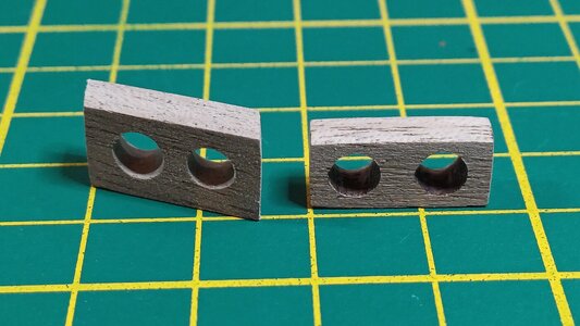
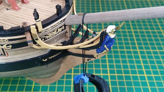
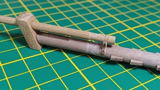
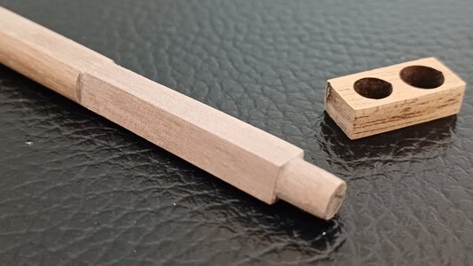
The bowsprit and jib boom were tapered to specification and a new bowsprit cap (left) crafted into the shape of a parallelogram so that the short edges would run parallel to the angle of the bowsprit and the long edges perpendicular to the keel. The supplied cap (right) is rectangular and too small to render into this sort of shape.

1150_20240307_hms_fly.jpg

The difference can be seen in the image below. The supplied rectangular cap (right) will not sit perpendicular to the keel once the bowsprit and jib boom are installed. The new cap (left) in the fashion of a parallelogram will achieve this.

1155_20240307_hms_fly.jpg

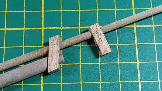
A recess is created at the top end of the bowsprit to accommodate the bees.

1160_20240307_hms_fly.jpg

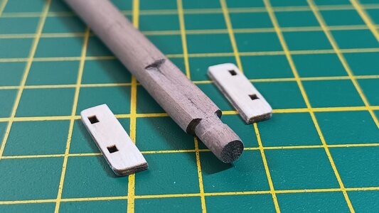
The gammoning cleats at the base of the bowsprit are best positioned with the bowsprit in place on the ship. The rope can then be aligned vertically with the slot that the rope will eventually pass through to bind the bowsprit.

1165_20240307_hms_fly.jpg

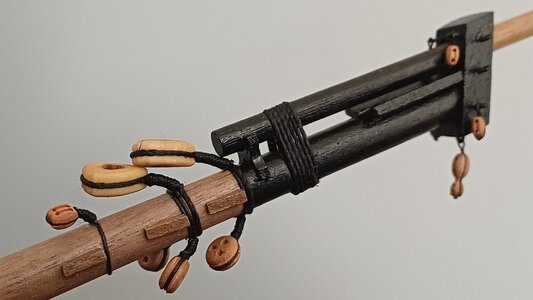
The bowsprit cap connects the bowsprit and jib boom spars. The base of the jib boom comes to rest on the jib boom saddle a short distance from the top of the bowsprit. A shallow recess was made just forward of the saddle to take lashings of rope to further secure the two spars.

1170_20240307_hms_fly.jpg

The hardware to make the bowsprit rigging-ready comes in the form of eyebolts, deadeyes and a variety of blocks: single, double, heart and violin. I followed a simple and effective method to rig the blocks to the spars. Click here to view a video of this method if you like.

1175_20240307_hms_fly.jpg

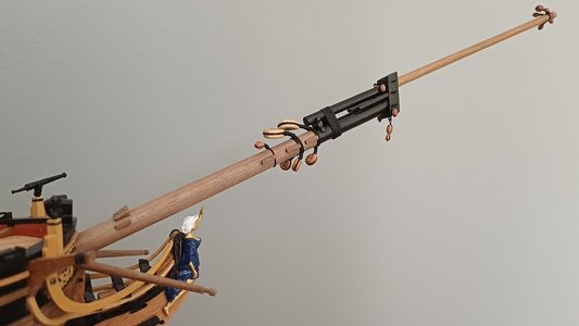
The bowsprit is dry-fitted at this stage as a mark of caution. The gammoning will be completed at the point when the bowsprit is fixed permanently to the ship.

1180_20240307_hms_fly.jpg

First spar done! (well, mostly anyway)

1185_20240307_hms_fly.jpg

Thanks for checking in :)

Mark
 
Last edited:
Onwards and upwards. The masts and spars are next, and the bowsprit was as good a spar as any to begin with. After a quick review of the plans I realised the enormous benefit a hobby lathe would bring to this part of the build. This however would be considered a luxury in my little shipyard, so, for now at least, a pencil, roll of sandpaper and a pair of calipers will have to suffice. :)

The bowsprit and jib boom were tapered to specification and a new bowsprit cap (left) crafted into the shape of a parallelogram so that the short edges would run parallel to the angle of the bowsprit and the long edges perpendicular to the keel. The supplied cap (right) is rectangular and too small to render into this sort of shape.

View attachment 433137

The difference can be seen in the image below. The supplied rectangular cap (right) will not sit perpendicular to the keel once the bowsprit and jib boom are installed. The new cap (left) in the fashion of a parallelogram will achieve this.

View attachment 433138

A recess is created at the top end of the bowsprit to accommodate the bees.

View attachment 433139

The gammoning cleats at the base of the bowsprit are best positioned with the bowsprit in place on the ship. The rope can then be aligned vertically with the slot that the rope will eventually pass through to bind the bowsprit.

View attachment 433140

The bowsprit cap connects the bowsprit and jib boom spars. The base of the jib boom comes to rest on the jib boom saddle a short distance from the top of the bowsprit. A shallow recess was made just forward of the saddle to take lashings of rope to further secure the two spars.

View attachment 433141

The hardware to make the bowsprit rigging-ready comes in the form of eyebolts, deadeyes and a variety of blocks: single, double, heart and violin. I followed a simple and effective method to rig the blocks to the spars. Click here to view a video of this method if you like.

View attachment 433142

The bowsprit is dry-fitted at this stage as a mark of caution. The gammoning will be completed at the point when the bowsprit is fixed permanently to the ship.

View attachment 433143

First spar done! (well, mostly anyway)

View attachment 433144

Thanks for checking in :)

Mark
What can I say more than "WELL DONE MATE"
Depending on how, then many models one will build in the future, there may be some Tools you would like, but many of these tools will only be used a few times. after that storet and get dusty etc. In my case when building it took about 3 years to make one -one for the hull, another for the deck plus and the last one masts. bowsprit and riggen-with sail a little more. under this process you use different tools- then some are stored until next build.
el capi
 
Very good quality - either prepared by the kit, and also by your work
we can see this on your close up photo
Very good
 
Onwards and upwards. The masts and spars are next, and the bowsprit was as good a spar as any to begin with. After a quick review of the plans I realised the enormous benefit a hobby lathe would bring to this part of the build. This however would be considered a luxury in my little shipyard, so, for now at least, a pencil, roll of sandpaper and a pair of calipers will have to suffice. :)

The bowsprit and jib boom were tapered to specification and a new bowsprit cap (left) crafted into the shape of a parallelogram so that the short edges would run parallel to the angle of the bowsprit and the long edges perpendicular to the keel. The supplied cap (right) is rectangular and too small to render into this sort of shape.

View attachment 433137

The difference can be seen in the image below. The supplied rectangular cap (right) will not sit perpendicular to the keel once the bowsprit and jib boom are installed. The new cap (left) in the fashion of a parallelogram will achieve this.

View attachment 433138

A recess is created at the top end of the bowsprit to accommodate the bees.

View attachment 433139

The gammoning cleats at the base of the bowsprit are best positioned with the bowsprit in place on the ship. The rope can then be aligned vertically with the slot that the rope will eventually pass through to bind the bowsprit.

View attachment 433140

The bowsprit cap connects the bowsprit and jib boom spars. The base of the jib boom comes to rest on the jib boom saddle a short distance from the top of the bowsprit. A shallow recess was made just forward of the saddle to take lashings of rope to further secure the two spars.

View attachment 433141

The hardware to make the bowsprit rigging-ready comes in the form of eyebolts, deadeyes and a variety of blocks: single, double, heart and violin. I followed a simple and effective method to rig the blocks to the spars. Click here to view a video of this method if you like.

View attachment 433142

The bowsprit is dry-fitted at this stage as a mark of caution. The gammoning will be completed at the point when the bowsprit is fixed permanently to the ship.

View attachment 433143

First spar done! (well, mostly anyway)

View attachment 433144

Thanks for checking in :)

Mark
Baai Mooi Mark. And I see her sailing around the Cape…SPLENDID. Cheers Grant
 
Onwards and upwards. The masts and spars are next, and the bowsprit was as good a spar as any to begin with. After a quick review of the plans I realised the enormous benefit a hobby lathe would bring to this part of the build. This however would be considered a luxury in my little shipyard, so, for now at least, a pencil, roll of sandpaper and a pair of calipers will have to suffice. :)

The bowsprit and jib boom were tapered to specification and a new bowsprit cap (left) crafted into the shape of a parallelogram so that the short edges would run parallel to the angle of the bowsprit and the long edges perpendicular to the keel. The supplied cap (right) is rectangular and too small to render into this sort of shape.

View attachment 433137

The difference can be seen in the image below. The supplied rectangular cap (right) will not sit perpendicular to the keel once the bowsprit and jib boom are installed. The new cap (left) in the fashion of a parallelogram will achieve this.

View attachment 433138

A recess is created at the top end of the bowsprit to accommodate the bees.

View attachment 433139

The gammoning cleats at the base of the bowsprit are best positioned with the bowsprit in place on the ship. The rope can then be aligned vertically with the slot that the rope will eventually pass through to bind the bowsprit.

View attachment 433140

The bowsprit cap connects the bowsprit and jib boom spars. The base of the jib boom comes to rest on the jib boom saddle a short distance from the top of the bowsprit. A shallow recess was made just forward of the saddle to take lashings of rope to further secure the two spars.

View attachment 433141

The hardware to make the bowsprit rigging-ready comes in the form of eyebolts, deadeyes and a variety of blocks: single, double, heart and violin. I followed a simple and effective method to rig the blocks to the spars. Click here to view a video of this method if you like.

View attachment 433142

The bowsprit is dry-fitted at this stage as a mark of caution. The gammoning will be completed at the point when the bowsprit is fixed permanently to the ship.

View attachment 433143

First spar done! (well, mostly anyway)

View attachment 433144

Thanks for checking in :)

Mark
A nice outcome of the bowsprit, with the paint and rigged blocks, Mark.
Regards, Peter
 
Onwards and upwards. The masts and spars are next, and the bowsprit was as good a spar as any to begin with. After a quick review of the plans I realised the enormous benefit a hobby lathe would bring to this part of the build. This however would be considered a luxury in my little shipyard, so, for now at least, a pencil, roll of sandpaper and a pair of calipers will have to suffice. :)

The bowsprit and jib boom were tapered to specification and a new bowsprit cap (left) crafted into the shape of a parallelogram so that the short edges would run parallel to the angle of the bowsprit and the long edges perpendicular to the keel. The supplied cap (right) is rectangular and too small to render into this sort of shape.

View attachment 433137

The difference can be seen in the image below. The supplied rectangular cap (right) will not sit perpendicular to the keel once the bowsprit and jib boom are installed. The new cap (left) in the fashion of a parallelogram will achieve this.

View attachment 433138

A recess is created at the top end of the bowsprit to accommodate the bees.

View attachment 433139

The gammoning cleats at the base of the bowsprit are best positioned with the bowsprit in place on the ship. The rope can then be aligned vertically with the slot that the rope will eventually pass through to bind the bowsprit.

View attachment 433140

The bowsprit cap connects the bowsprit and jib boom spars. The base of the jib boom comes to rest on the jib boom saddle a short distance from the top of the bowsprit. A shallow recess was made just forward of the saddle to take lashings of rope to further secure the two spars.

View attachment 433141

The hardware to make the bowsprit rigging-ready comes in the form of eyebolts, deadeyes and a variety of blocks: single, double, heart and violin. I followed a simple and effective method to rig the blocks to the spars. Click here to view a video of this method if you like.

View attachment 433142

The bowsprit is dry-fitted at this stage as a mark of caution. The gammoning will be completed at the point when the bowsprit is fixed permanently to the ship.

View attachment 433143

First spar done! (well, mostly anyway)

View attachment 433144

Thanks for checking in :)

Mark
ANOTHER FANTASTIC BUILD
 
Of the three masts that need to be assembled I started with the foremast for no other reason than it seemed next in line after the bowsprit. All three lower masts share similar characteristics and only differ in the degree hardware they carry. The first step was to mark and shape the sections of mast that are rounded, squared and tapered, for which a razor-sharp hobby knife and a set of mini files proved very useful friends.

1190_20240506_hms_fly.jpg

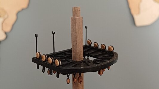
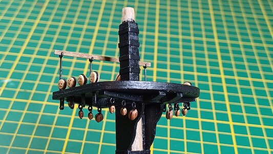
The mast top assemblies are an exercise on their own, a mixture of crosstrees, tressletrees, ringbolts, stanchions, bolsters and a myriad of holes and blocks for future rigging purposes.

1195_20240506_hms_fly.jpg

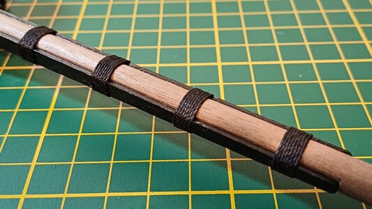
The cheeks and bibs are installed on either side of the mast and bound by a series of mast rope wooldings. The top edge of the bib supports the mast top assembly and is angled slightly to accommodate any rake the mast may have. This affects the mizzenmast the most which on HMS Fly carries a rake more severe than the foremast or mainmast.

1200_20240506_hms_fly.jpg

Thin black tape is used to represent the iron bands that support the masthead. Sequence is everything here. The bands can only be installed after the mast top is in place otherwise the mast can not pass through the narrow gap of the trestletrees. Similarly, the blocks, tie cleats and mast caps that all attach to the top of the mast are likely to hamper the lower shroud loops and will have to wait their turn until later.

1205_20240506_hms_fly.jpg

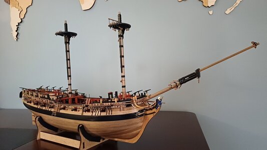
The lower foremast and mainmast are mostly complete and work has yet to begin on the mizzenmast. Everything that can be dry-fitted is dry-fitted at this stage. I wouldn't want to tempt fate by glueing anything significant in place just yet.

1210_20240506_hms_fly.jpg

Thanks for checking in.

Mark :)
 
Last edited:
Of the three masts that need to be assembled I started with the foremast for no other reason than it seemed next in line after the bowsprit. All three lower masts share similar characteristics and only differ in the degree hardware they carry. The first step was to mark and shape the sections of mast that are rounded, squared and tapered, for which a razor-sharp hobby knife and a set of mini files proved very useful friends.

View attachment 445967

The mast top assemblies are an exercise on their own, a mixture of crosstrees, tressletrees, ringbolts, stanchions, bolsters and a myriad of holes and blocks for future rigging purposes.

View attachment 445968

The cheeks and bibs are installed on either side of the mast and bound by a series of mast rope wooldings. The top edge of the bib supports the mast top assembly and is angled slightly to accommodate any rake the mast may have. This affects the mizzenmast the most which on HMS Fly carries a rake more severe than the foremast or mainmast.

View attachment 445969

Thin black tape is used to represent the iron bands that support the masthead. Sequence is everything here. The bands can only be installed after the mast top is in place otherwise the mast can not pass through the narrow gap of the trestletrees. Similarly, the blocks, tie cleats and mast caps that all attach to the top of the mast are likely to hamper the lower shroud loops and will have to wait their turn until later.

View attachment 445970

The lower foremast and mainmast are mostly complete and work has yet to begin on the mizzenmast. Everything that can be dry-fitted is dry-fitted at this stage. I wouldn't want to tempt fate by glueing anything significant in place just yet.

View attachment 445971

Thanks for checking in.

Mark :)
The mast and masthead are looking very nice, Mark. The black accents are great.
Regards, Peter
 
Back
Top