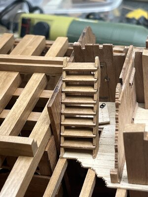
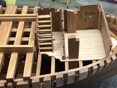
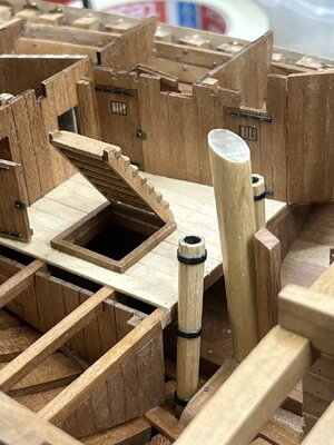
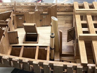
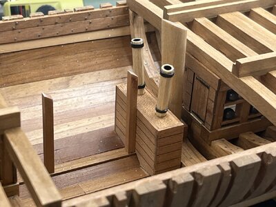
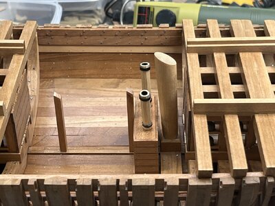
What a beauty Uwe, I still love these cutaway models.
-

Win a Free Custom Engraved Brass Coin!!!
As a way to introduce our brass coins to the community, we will raffle off a free coin during the month of August. Follow link ABOVE for instructions for entering.
-

PRE-ORDER SHIPS IN SCALE TODAY!
The beloved Ships in Scale Magazine is back and charting a new course for 2026!
Discover new skills, new techniques, and new inspirations in every issue.
NOTE THAT OUR FIRST ISSUE WILL BE JAN/FEB 2026
You are using an out of date browser. It may not display this or other websites correctly.
You should upgrade or use an alternative browser.
You should upgrade or use an alternative browser.
HMS GRANADO - full hull - POF kit by CAF in 1:48 - by Uwe
Uwe,
Wow - just catching up - Agree beyond excellent
Wow - just catching up - Agree beyond excellent
Uwe, this is a party for the eyes, what a beautiful ship you are making, and what a way to display it.If it is too boring - please scroll fast through the pics ........
I love it
you are right and I am working on it ..... means I think about it how to make it - I guess it will be brasstubes somehow similar like the Leightley-modelBut you need to come up with a better alternative to the sanding blocks, they detract from the model.
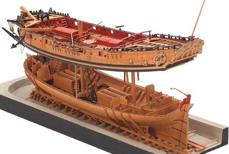
but with three tubes, because I will cut the masts
In my opinion Lightley made a small mistake, because the masts have a small inclination of 2 or 3 percent, so therefore with the height distance the upper part has to be more aft - or it is looking more dynamic .....
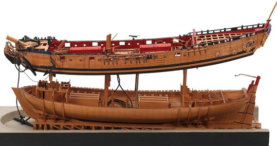
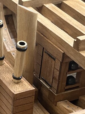
A good questionIn the first picture you posted, are those doors right next to the mast? How would you open them?
we can see on the Lightley model, that the mast has a bigger distance from the doors
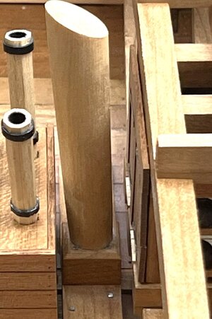
I followed here more, or better strict the information given by Goodwin in his drawings - and here the mast food is much closer to the doors or shell storage
I can imagine, that Lightley installed relatively late the mast and the mastfoot, therefore his main mast is not inclined and more or less vertical - which is not really correct
I argue for my model,
that the doors would be able to be opened - The small inclination of the mast is more visible
-> one dead you have to die
and to all writting some comments or hitting the like button => Many Many thanks for this and your interest in my building log
I was thinking that the top half could just hang on longer mast sections. The mast rake may cause some issues but I still think that's how I would try it.
I can only repeat it, simply a super model, beautifully executed.
magnificent workmanship. Great attention to detail. Bravo.
- Joined
- Dec 16, 2016
- Messages
- 1,181
- Points
- 493

Ewe, great pictures of a super build, I can only add my admiration on your achievementsome more photos
the pumps and mast stumps
View attachment 447559
View attachment 447560
the two segments to see how it will look like
from the unplanked side
View attachment 447561
View attachment 447562
View attachment 447566
and the planked side
View attachment 447563
View attachment 447564
View attachment 447565
some views from the top down
View attachment 447567
View attachment 447568
View attachment 447569
View attachment 447570
View attachment 447571
and the two halfs next to each other
View attachment 447572
View attachment 447573
View attachment 447574
Many Thanks for your interest ....
That looks wonderful !!!
Ditto and dittoI agree with Adi.
Ps it's: Stairway to heaven
Good morning Uwek. A question for you. I'm learning for my next ship which I plan to do a tad more accurate than my previous. Treenails. British ships during this period, used a combination of wood and metal nailing. My interpretation : the decks and outer hull were wood nails, while much of the interior and bulkwarks were metal. I think the wales are also metal. Do you have any good references I can look at regarding this. I have some French references, however they used different configurations to the British. Cheers Grant
Many Thanks to @pianoforte , @Steef66 , @Mirek , @KurtFink , @Ken , @Corsair and @GrantTyler for your kind words and comments and also for all the likes received - I like it very much to get comments and try to answer all the question, especially if I do know the answer - or to give my try to answer, also and maybe especially when there is some additional research necessary.
somehow, the use of wooden treenails, or bolts (circular or rectangle, in iron or copper) on my model(s) is off course somehow my personal taste, but also based on some knowledge from different publications. And this "knowledge" is grown over the years with the different models
My Granado model is following as much as possible the given informations by Peter Goodwin in his Anatomy of Ships series
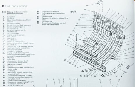
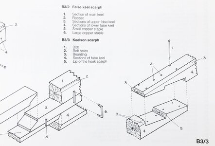
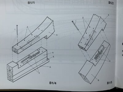
so let us take a first look here - in some sketches are some iron bolts shown (photos taken from my hard-disc of my PC - there are more in the book)
for the frames and the keelson
for the keel
also the mast foots
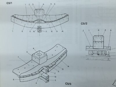
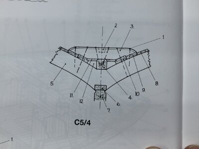
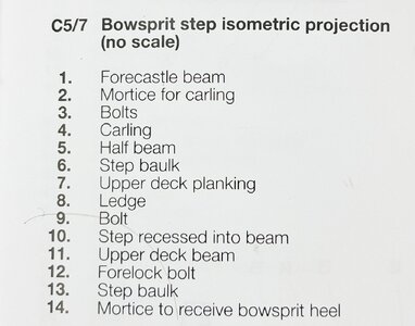
Bowsprit step
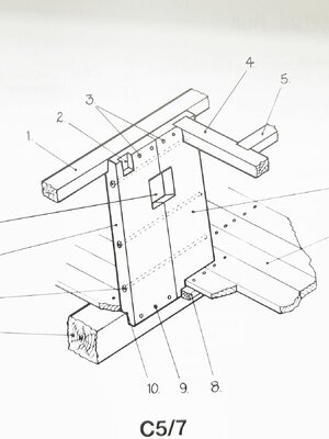
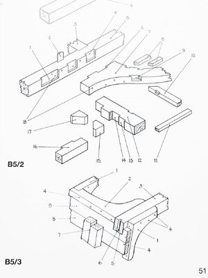
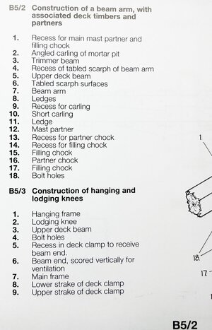
lodging and hanging knees + beam arms connections
I am pretty sure, that there is also something visible or written about using bolts for the wales and / or the inner thick stuff
But I think, that all structural elements with some specific thickness were connected with metal / iron bolts and not with wooden treenails - they can not be made so long
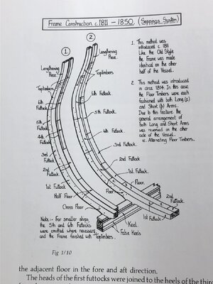
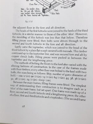
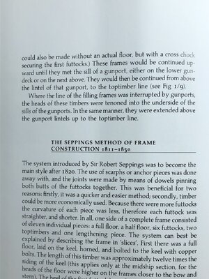
slightly contrary about the construction of frames (especially related to chock connections) is written in Laverys book - here he is writing "bolts and trennals"
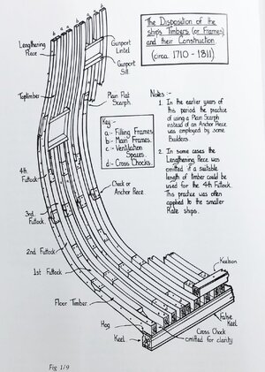

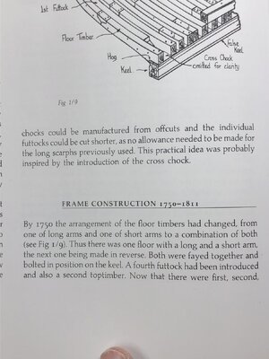
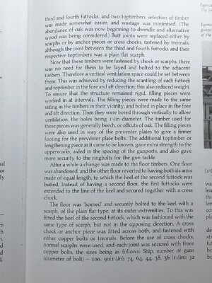
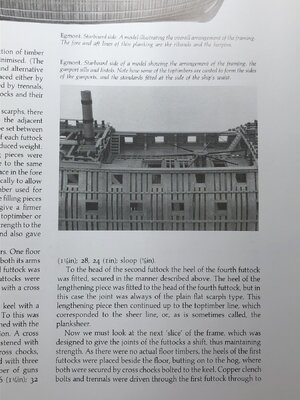
Dear Grant,Good morning Uwek. A question for you. I'm learning for my next ship which I plan to do a tad more accurate than my previous. Treenails. British ships during this period, used a combination of wood and metal nailing. My interpretation : the decks and outer hull were wood nails, while much of the interior and bulkwarks were metal. I think the wales are also metal. Do you have any good references I can look at regarding this. I have some French references, however they used different configurations to the British. Cheers Grant
somehow, the use of wooden treenails, or bolts (circular or rectangle, in iron or copper) on my model(s) is off course somehow my personal taste, but also based on some knowledge from different publications. And this "knowledge" is grown over the years with the different models
My Granado model is following as much as possible the given informations by Peter Goodwin in his Anatomy of Ships series
Book review - Book Review: "The Bomb Vessel GRANADO (Anatomy of the Ship)" by Peter Goodwin
Book Review: The Bomb Vessel GRANADO (Anatomy of the Ship) by Peter Goodwin Hardcover: 128 pages Publisher: Conway Maritime Press; New edition edition (21 April 2005) Language: English Product Dimensions: 26 x 1.9 x 24.1 cm Synopsis: Built as a floating siege engine able to...
shipsofscale.com
so let us take a first look here - in some sketches are some iron bolts shown (photos taken from my hard-disc of my PC - there are more in the book)
for the frames and the keelson

for the keel


also the mast foots


Bowsprit step


lodging and hanging knees + beam arms connections


I am pretty sure, that there is also something visible or written about using bolts for the wales and / or the inner thick stuff
But I think, that all structural elements with some specific thickness were connected with metal / iron bolts and not with wooden treenails - they can not be made so long
slightly contrary about the construction of frames (especially related to chock connections) is written in Laverys book - here he is writing "bolts and trennals"


Hallo Grant,Good morning Uwek. A question for you. I'm learning for my next ship which I plan to do a tad more accurate than my previous. Treenails. British ships during this period, used a combination of wood and metal nailing. My interpretation : the decks and outer hull were wood nails, while much of the interior and bulkwarks were metal. I think the wales are also metal. Do you have any good references I can look at regarding this. I have some French references, however they used different configurations to the British. Cheers Grant
take also a look at this film (today posted by @Steef66 - once more many thanks) which is making the dimensions visible
Build of a wooden ship.
Just found this, it shows a time of craftsmen building a huge wooden ship. https://www.danmarkpaafilm.dk/film/skibet
shipsofscale.com
BTW: also very interesting to the end of the film is the fixing of the deck planking with iron bolts and the closing of the holes with wooden plugs
Uwe's response should answer your questions.A question for you. I'm learning for my next ship which I plan to do a tad more accurate than my previous. Treenails. British ships during this period, used a combination of wood and metal nailing. My interpretation : the decks and outer hull were wood nails, while much of the interior and bulkwarks were metal. I think the wales are also metal. Do you have any good references I can look at regarding this.
is written in Laverys book - here he is writing "bolts and trennals
I think this is a typo but I may be wrong...
You are Correct ..... it is from this bookI think this is a typo but I may be wrong..... it looks like the last 8 pages are copies of pages from Peter Goodwin's book The Construction and Fitting of the English Man of War, first published in 1987 rather than from a book by Brian Lavery.
Book review - The Construction and Fitting of the Sailing Man-of-War, 1650-1850" by Peter Goodwin
From the early beginning of this review: This book is very recommended and is a invaluable reference for ship modeling. In my opinion a "Must Have" The Construction and Fitting of the Sailing Man-of-War, 1650-1850 (Conway's History of Sail) (Hardcover) by Peter Goodwin (Author) Hardcover: 288...
shipsofscale.com
Yes - definitely helpful - often I mix them upI would absolutely agree Uwe, Goodwins book as well as The Arming and Fitting of English Ships of War by Lavery are extremely useful for kit builders, kit bashers, as well as scratch builders.
Allan
Book review - Book Review / Look Inside: "The Arming and Fitting of English Ships of War, 1600-1815" by Brian Lavery
Arming and Fitting of English Ships of War 1600-1815 by Brian Lavery Hardcover: 319 pages Publisher: Naval Inst Pr; 1st Edition edition (March 1, 1988) Language: English ISBN-10: 0870210092 ISBN-13: 978-0870210099 Product Dimensions: 10.2 x 1 x 12 inches Shipping Weight: 3.9 pounds...
shipsofscale.com
and the third one very helpful is the Lees
Book review - The Masting and Rigging of English Ships of War, 1625-1860" by James Lees
An other cornerstone in each private library describing the mast, spars and the complex rigging work should be The Masting and Rigging of English Ships of War, 1625-1860 By James Lees Publisher: Naval Institute Press; 2nd Rev edition (October 1984) Pages: 212 ISBN-10: 0870219480...
shipsofscale.com


