So sorry to hear of your troubles Paul, I wish you a speedy recovery.
The work on the rudder is exceptional for someone with both eyes let alone one!
The work on the rudder is exceptional for someone with both eyes let alone one!

Eyes! Mere windows to distractions of all stripe. Way to stay focused on the ship, even as half-blind!Hello Friends,
I've been having a problem with one of my eyes (retinal bleed) and I went in today for some treatment and now I can hardly see at all (temporary). Of course that means I can't work on my ship.
But I couldn't sleep last night (anxious about my procedure) so I ended up in the Kattner Shipyard installing gudgeons and the rudder before my eye appointment. Here is the result (all accomplished with only one functioning eye
).
View attachment 428358
View attachment 428359
View attachment 428360
View attachment 428363
View attachment 428362
I can't wait until I can see clearly again to learn how it all turned out. Thanks for the visit!

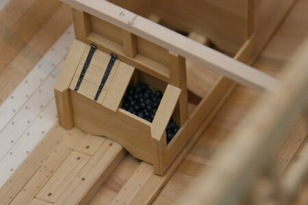
brass ball bearings (Amazon) - they look rough only because I doused the pile with watered down white glue to fix them in placeLike the interior measuring tool also!
Is that lead fishing shot in the locker or did you form it yourself?
Everything is looking incredible and way to go to the extra effort on the lower deck!
Thank you, Heinrich! I wish I had the same confidence in me that you do...I wasn't expecting anything else other than that you would add the lower beams!Seriously, though, I am glad you did, because it adds the detail that the build deserves. There are so many noteworthy elements at work here: the desire to build the best model you can, the vision to envisage the visual effect, the creativity and faultless execution in creating the cambered beams, and the innovative measuring tool ensuring accurate measurement. And the best of it all, is that you make it look so easy!


Hi Paul, like everyone has said, absolutely amazing, it just doesn’t come any better. I wish you a good and speedy recovery with your eye, you’ll need it to keep up this level of fine detail.I mentioned previously that the LSS Kingfisher kit that forms the basis for this build made no provision for the fore and aft hold platforms I showed earlier. In a similar way it does not include materials for a lower deck.
This is by no means a criticism of this excellent kit. Mr. Hunt worked directly with the authors of the TFFM book series in creating this kit and was obviously doing everything he could to help the builder succeed, and to focus resources (and time) on the most visible parts of the completed model.
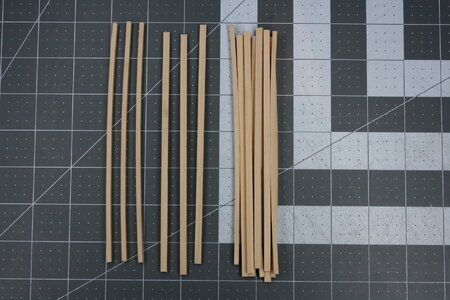
My interests are somewhat different, so the first challenge I faced was figuring out how to create lower deck beams with a camber. The roundup on these beams is a mere 3 inches (1.6 mm at scale) but I did not think this could be ignored. While I suppose I could have steamed and bent the beams, I doubted whether that could be done uniformly and with long-term stability.
The finished beams are to be 8" wide and 6" deep (4.2 mm x 3.2 mm at scale) so I selected a panel from my meager supply of boxwood and headed to the garage...
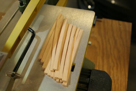
Rough cutting beams on a scroll saw:
View attachment 429546
View attachment 429547
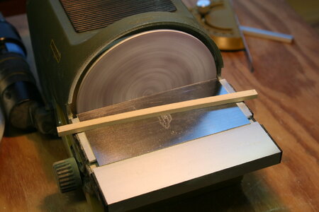
Next, I finished the convex (upper) face using a disc sander:
View attachment 429548
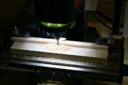
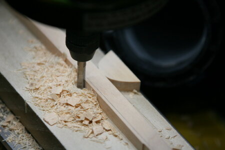
And then finished the concave (lower) face using a mill with a jig:
View attachment 429549
View attachment 429550
I then ran these through a thickness sander to establish the proper beam width (my available panel was marginally oversized):
View attachment 429551
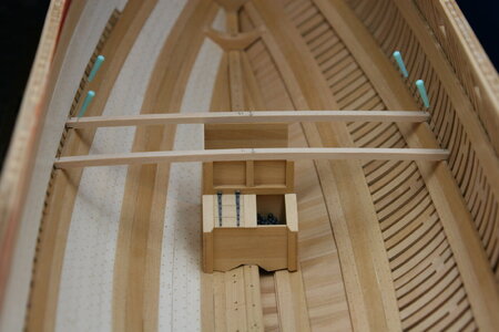
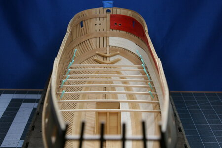
Now, moving to the model, I started with the two beams that relate to the well house / shot locker because it was easy to locate that structure on the ship:
View attachment 429553
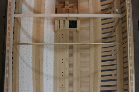
I quickly learned how difficult it is to size and fit these beams, so I made myself a tool to measure spans inside the ship:
View attachment 429555
Slightly crimping the tube part allowed it to friction-grip the rod part in a very satisfying way. This allowed me to measure and then transfer that measurement directly to the beams. I'll be making more of these in various sizes!
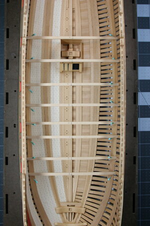
Eight beams in place:
View attachment 429557
View attachment 429559
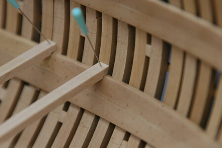
The beams should be 'let down' into notches on the deck clamps. Of course, that would prevent me from moving the beams in the future and that seemed unwise (I've learned I don't transfer measurements from the plans to the ship very well).
Anyway, I just made some 1" notches (0.5 mm) on the bottom of the beams. By the time I refine these joints no one will be able to tell that I cheated.
View attachment 429558
Bonus: shot added to the shot locker...
View attachment 429554
My thanks for the visit! And I enjoy visiting so many of your build reports as well!
Paul,
please check your original drawings of the ship. Fly and Atalanta do not have curved deck beams on the orlop deck. So you make perhaps a lot of work which is not necessary. Wonderful work. Now you are on your way to the dark side of modelbuilding.


 It NEVER occurred to me that there might be a variation across the line!

 .
.I like your cambered beams - well done my friend......It's the simple joys in life that matter most boys!
