I am in agreement with Peter, this is not an easy part to make, and the result is well made.

-

SUBSCRIBE TO SHIPS IN SCALE TODAY!
The beloved Ships in Scale Magazine is back and charting a new course for 2026!
Discover new skills, new techniques, and new inspirations in every issue.
NOTE THAT OUR NEXT ISSUE WILL BE MARCH/APRIL 2026 -

Win a Free Custom Engraved Brass Coin!!!
As a way to introduce our brass coins to the community, we will raffle off a free coin during the month of August. Follow link ABOVE for instructions for entering.
You are using an out of date browser. It may not display this or other websites correctly.
You should upgrade or use an alternative browser.
You should upgrade or use an alternative browser.
Kolderstok. Fluyt in oak
- Thread starter janzwart
- Start date
- Watchers 29
-
- Tags
- fluit kolderstok
- Joined
- Apr 10, 2020
- Messages
- 146
- Points
- 213

Update 22.
The new hemp hole frame is in place and gaps have been sealed. The connection to the heelboard will also be improved a bit in due course.
The state now is as below:
I have now also cut open the planned opening in the stern. A tip of a weld has fallen out, will still be put back. Also you can now see the cabin, the helmsman place and the hold below it again. Hard to photograph but the idea is clear.
To be continued.
Last edited:

Nice work, Jan!
- Joined
- Apr 10, 2020
- Messages
- 146
- Points
- 213
Update 23
I am not satisfied with the gradient of the battens toward the transom.
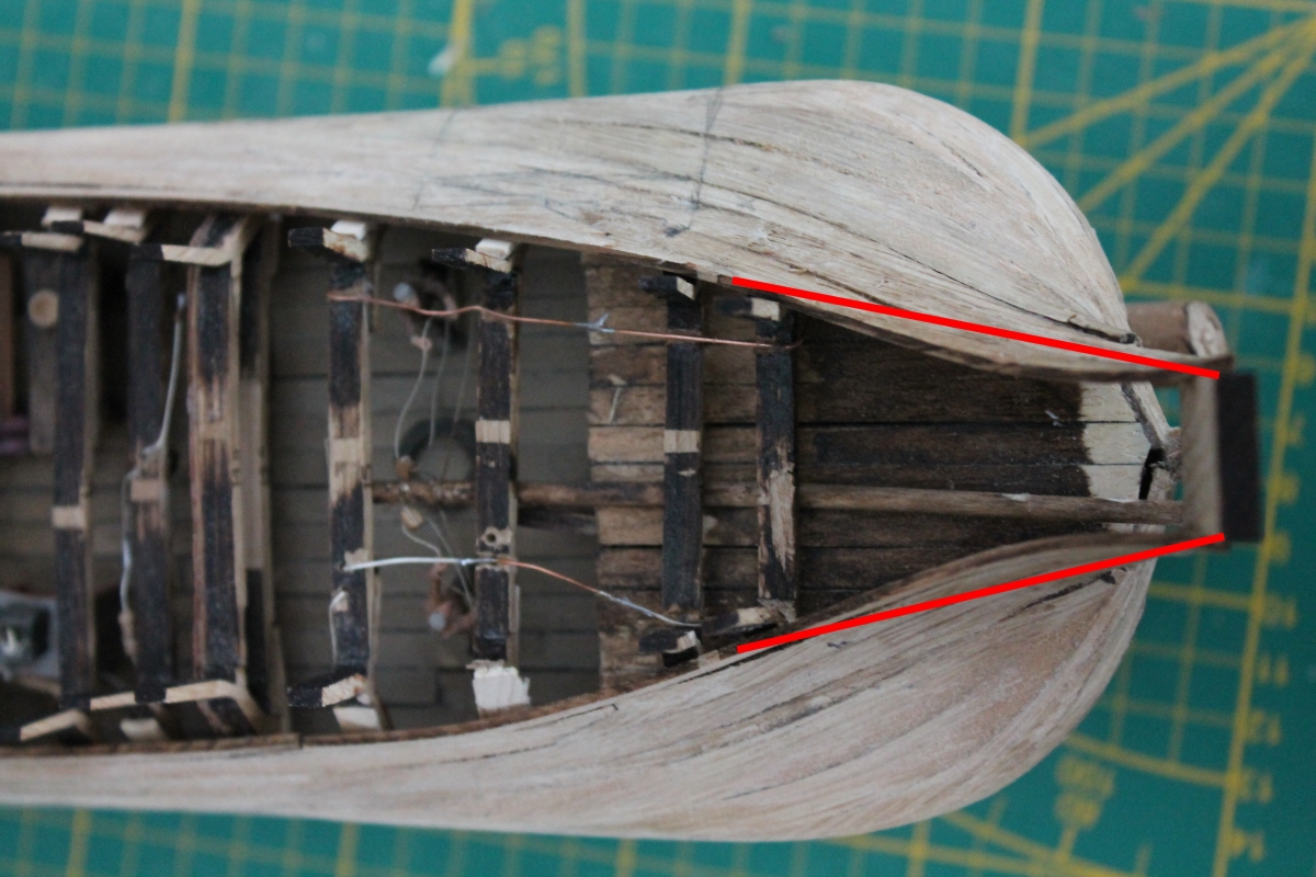
I placed one or two battens further but that curve still staying there. Whereas that piece of the skin is just flat with no curve. You can see that in all the photos of some ships.
Here is a photo of the Batavia, still in good shape, but also without a curve.
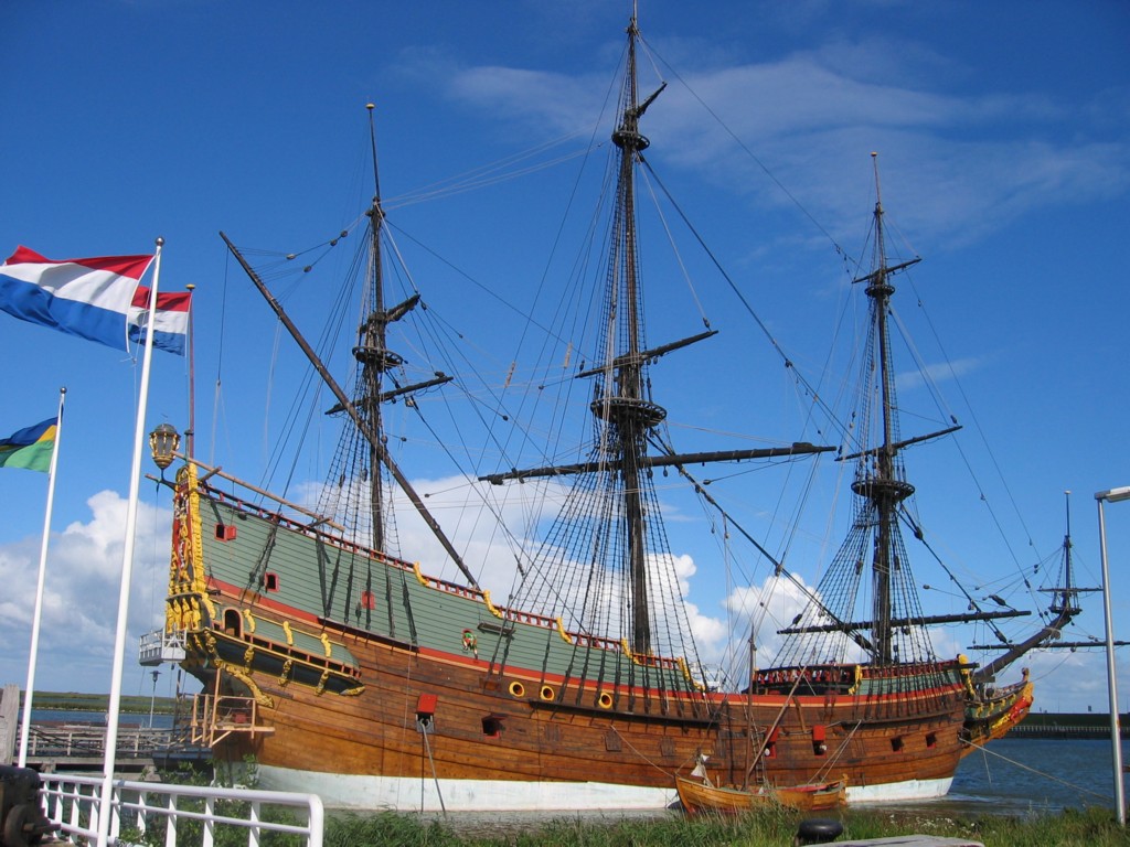
And also in Kolderstok's manual, this is meant without rounding.
So I decided to loosen it up again and try to get it straighter.
Then I wet the last part of the battens well with a brush and placed pieces of solid wood on the inside and outside and clamped them firmly to make it straight. Unfortunately, I didn't take a picture of that.
After a while I removed the wooden pieces and moved the whole thing back into position and put it in the clamps without glue.
When everything was seated properly I applied diluted wood glue to the seams which sucked in neatly.
After drying this is the result:

When repositioning, I tried to put the straight shape in with an attachment but I couldn't get it stable enough. Everything collapsed again. Afterwards I did check the shape with it.

I still need to do something about the transom, it's not quite perpendicular to the centerline. I also had the idea of modifying that whole transom.
The rectangular piece of transom is one piece of wood 4mm thick and 15mm wide and 35mm high. In reality, this would then be (times 72) 28.8 x 108 x 252 cm³. I had wanted to replace this with two beams with battens in between. But in retrospect, I think the difficulty of this kit should then have been rated 7 stars.
Another hurdle overcome, ??????? to go.
To be continued
I am not satisfied with the gradient of the battens toward the transom.
I placed one or two battens further but that curve still staying there. Whereas that piece of the skin is just flat with no curve. You can see that in all the photos of some ships.
Here is a photo of the Batavia, still in good shape, but also without a curve.
And also in Kolderstok's manual, this is meant without rounding.
So I decided to loosen it up again and try to get it straighter.
Then I wet the last part of the battens well with a brush and placed pieces of solid wood on the inside and outside and clamped them firmly to make it straight. Unfortunately, I didn't take a picture of that.
After a while I removed the wooden pieces and moved the whole thing back into position and put it in the clamps without glue.
When everything was seated properly I applied diluted wood glue to the seams which sucked in neatly.
After drying this is the result:
When repositioning, I tried to put the straight shape in with an attachment but I couldn't get it stable enough. Everything collapsed again. Afterwards I did check the shape with it.
I still need to do something about the transom, it's not quite perpendicular to the centerline. I also had the idea of modifying that whole transom.
The rectangular piece of transom is one piece of wood 4mm thick and 15mm wide and 35mm high. In reality, this would then be (times 72) 28.8 x 108 x 252 cm³. I had wanted to replace this with two beams with battens in between. But in retrospect, I think the difficulty of this kit should then have been rated 7 stars.
Another hurdle overcome, ??????? to go.
To be continued
Last edited:
- Joined
- Apr 10, 2020
- Messages
- 146
- Points
- 213
Update 24
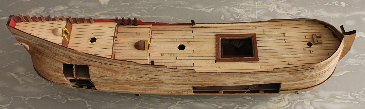
The stern is now planked to the top and updated a bit. It now sits to my liking.
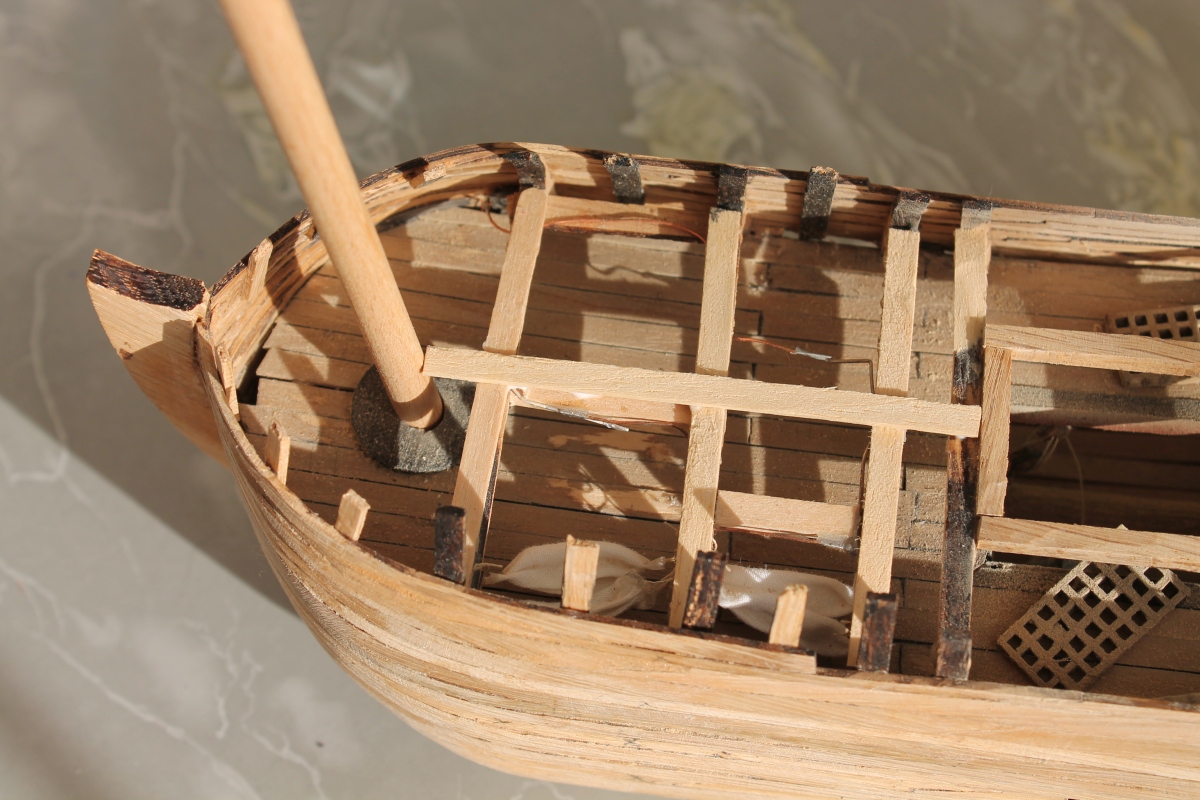
This is seen from the side,
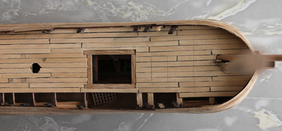
and this from above.
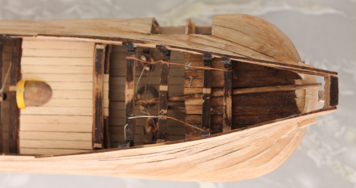
That weird S-bend is out. And the first deck has also been laid. Here you can also clearly see the tiller controls. It looks like the tiller is sticking up above the place for the mizzen mast but the tiller can still slide back a bit.
This is the beginning of the deck above the galley and "dining room."
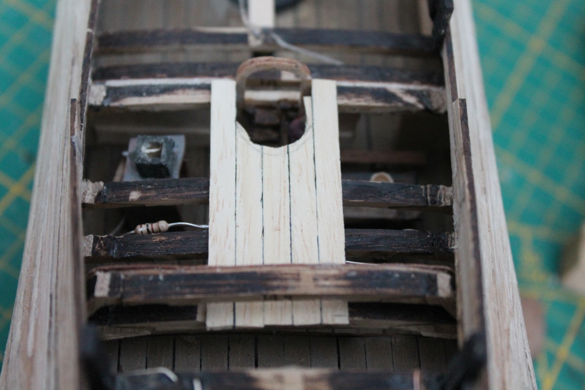
I want to leave the door to that open to give visibility. But that also means that the turret on the deck should be open from below and there should be a set of stairs below it. So this one.
And the steps in the "dining room" are a little unfortunate in relation to the table and bench with an eater.
After planking the deck closed, let's check how it will look.
The burning galley is easy to see.
Now I made a start on the middle foredeck.
But first I made the frame for the large hatch. The planking closes against that. Because I made a mast track for the fore mast on the plywood, very hard to see, and the deck above it already has a grommet, the location of the fore mast is already determined. And I have to fit the intermediate deck around the mast. I cannot plank this tightly and then put in a hole for the mast somewhere at random. Hence the mast is already loose in there.
To be continued.
The stern is now planked to the top and updated a bit. It now sits to my liking.
This is seen from the side,
and this from above.
That weird S-bend is out. And the first deck has also been laid. Here you can also clearly see the tiller controls. It looks like the tiller is sticking up above the place for the mizzen mast but the tiller can still slide back a bit.
This is the beginning of the deck above the galley and "dining room."
I want to leave the door to that open to give visibility. But that also means that the turret on the deck should be open from below and there should be a set of stairs below it. So this one.
And the steps in the "dining room" are a little unfortunate in relation to the table and bench with an eater.
After planking the deck closed, let's check how it will look.
The burning galley is easy to see.
Now I made a start on the middle foredeck.
But first I made the frame for the large hatch. The planking closes against that. Because I made a mast track for the fore mast on the plywood, very hard to see, and the deck above it already has a grommet, the location of the fore mast is already determined. And I have to fit the intermediate deck around the mast. I cannot plank this tightly and then put in a hole for the mast somewhere at random. Hence the mast is already loose in there.
To be continued.
Last edited:
A major re-do at the stern with a nice result, Jan.Update 24
The stern is now planked to the top and updated a bit. It now sits to my liking.
This is seen from the side,

and this from above.

That weird S-bend is out. And the first deck has also been laid. Here you can also clearly see the tiller controls. It looks like the tiller is sticking up above the place for the mizzen mast but the tiller can still slide back a bit.
This is the beginning of the deck above the galley and "dining room."

I want to leave the door to that open to give visibility. But that also means that the turret on the deck should be open from below and there should be a set of stairs below it. So this one.

And the steps in the "dining room" are a little unfortunate in relation to the table and bench with an eater.

After planking the deck closed, let's check how it will look.

The burning galley is easy to see.
Now I made a start on the middle foredeck.

But first I made the frame for the large hatch. The planking closes against that. Because I made a mast track for the fore mast on the plywood, very hard to see, and the deck above it already has a grommet, the location of the fore mast is already determined. And I have to fit the intermediate deck around the mast. I cannot plank this tightly and then put in a hole for the mast somewhere at random. Hence the mast is already loose in there.
To be continued.
regards, Peter
- Joined
- Apr 10, 2020
- Messages
- 146
- Points
- 213
Update 25
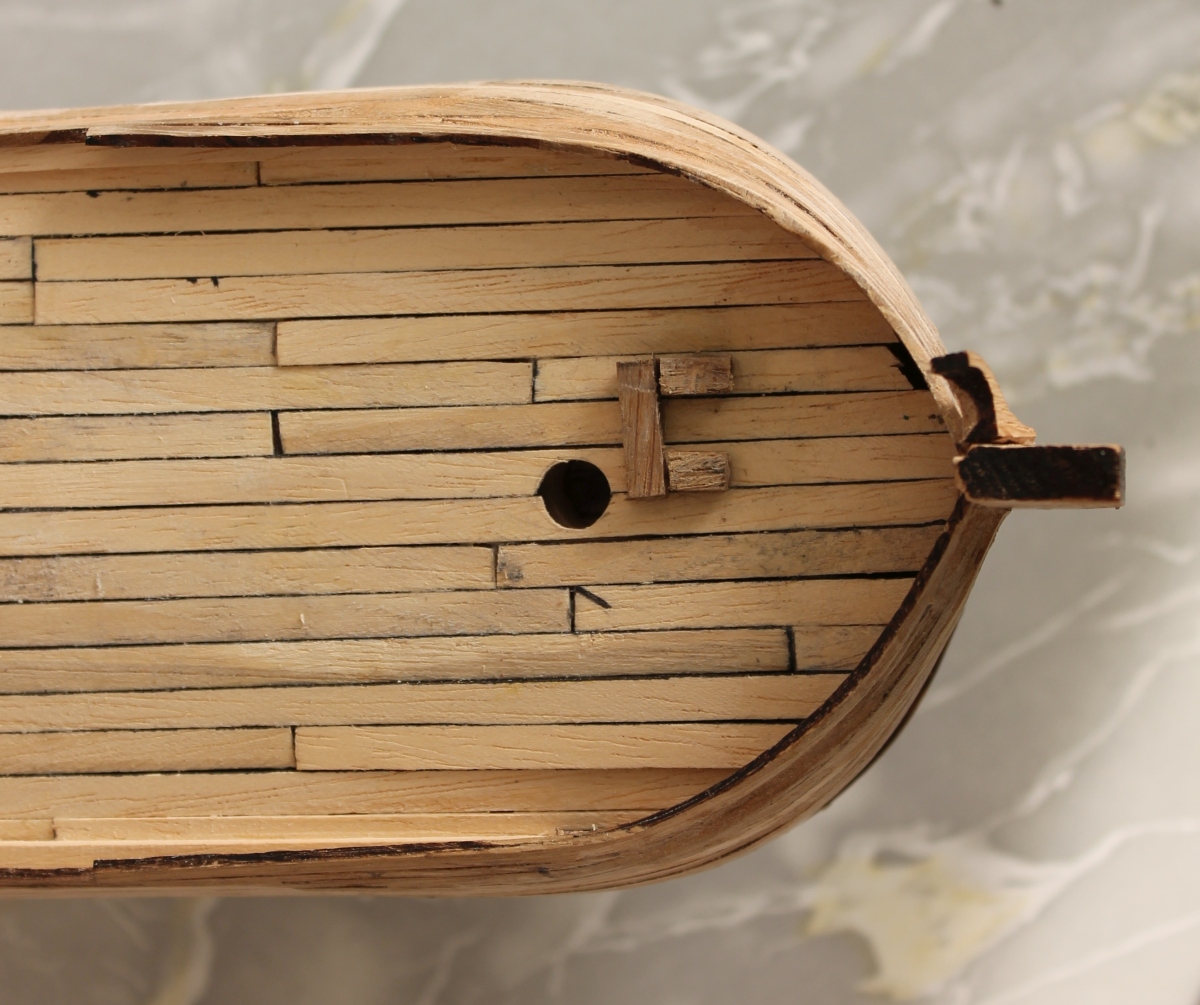
Now that the stern is nicely restored it is the turn of the bow.
After the center deck I continued with the large deck forward.
It looks a lot like this, but then you have to look a little closer. Here is also the jib mast (=blurry spot on the right) and the bowsprit in there.
The intention is that before the mast the beting will be placed with a nail bank. Now the bucket deck will be above this so that the passage of the bowsprit through this deck will be slightly forward. But there is only a 2 cm space left between mast and stem.
Then how is that on the models of other builders ?
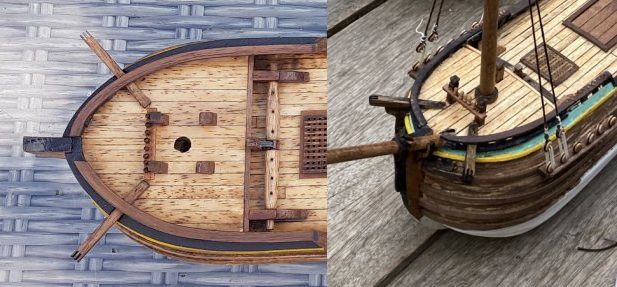
Left: Hans Groenenberg and on the right *Hans* Kolderstok. Both pictures show that that distance is significantly larger. How is that possible ? What did I do wrong then ?
I determined the location of the jib mast early on because the base of the mast is somewhat visible through the side opening. Incidentally, that is very disappointing and little of it is visible.
I printed out the drawing of the upper deck from the construction description to scale and put it on my model.
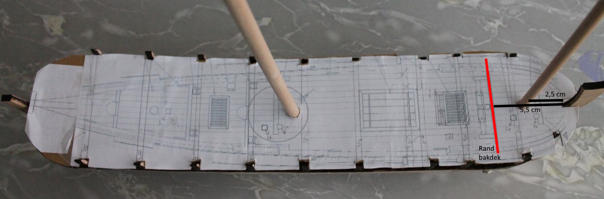
This shows that in my case the mast is slightly forward or on the center of the bucket deck. In the pictures of both Hansen's the mast is slightly behind the center so a little more backwards. Half to a full inch or so. That's quite a lot in such a small space.
Then if we look more carefully at the deck the big hatch is not exactly in the middle. The longitudinal side beams are exactly between the deck beams but the hatch is slightly shorter to keep it flush with the hatch below. That doesn't look pretty. So the part of the deck shown below is going out and needs to be better. At the same time, I then need to see how I can move the jib mast slightly aft.
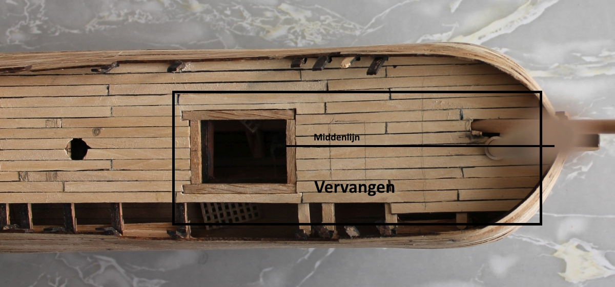
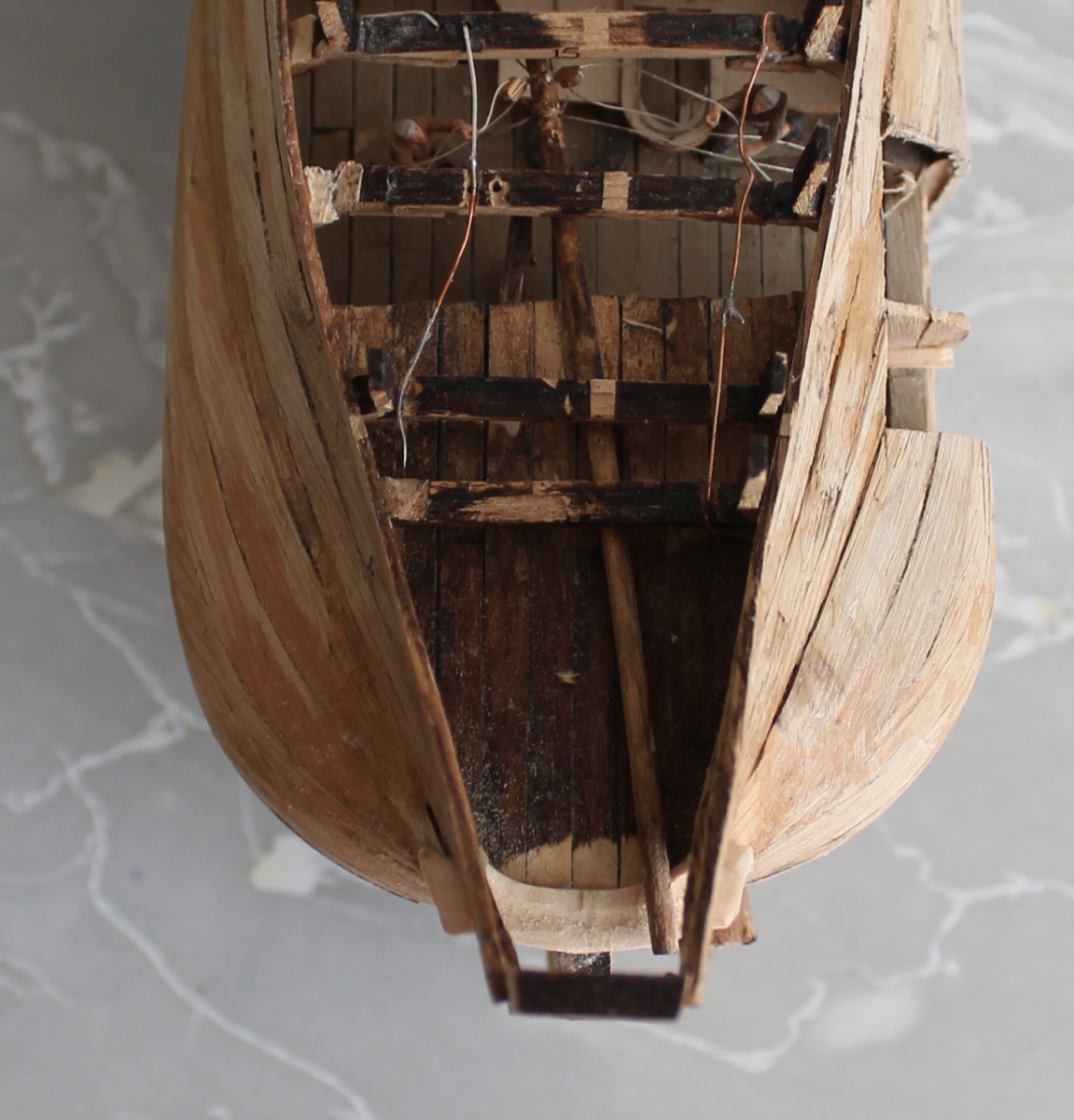
And disassembled.
To be continued
Now that the stern is nicely restored it is the turn of the bow.
After the center deck I continued with the large deck forward.
It looks a lot like this, but then you have to look a little closer. Here is also the jib mast (=blurry spot on the right) and the bowsprit in there.
The intention is that before the mast the beting will be placed with a nail bank. Now the bucket deck will be above this so that the passage of the bowsprit through this deck will be slightly forward. But there is only a 2 cm space left between mast and stem.
Then how is that on the models of other builders ?
Left: Hans Groenenberg and on the right *Hans* Kolderstok. Both pictures show that that distance is significantly larger. How is that possible ? What did I do wrong then ?
I determined the location of the jib mast early on because the base of the mast is somewhat visible through the side opening. Incidentally, that is very disappointing and little of it is visible.
I printed out the drawing of the upper deck from the construction description to scale and put it on my model.
This shows that in my case the mast is slightly forward or on the center of the bucket deck. In the pictures of both Hansen's the mast is slightly behind the center so a little more backwards. Half to a full inch or so. That's quite a lot in such a small space.
Then if we look more carefully at the deck the big hatch is not exactly in the middle. The longitudinal side beams are exactly between the deck beams but the hatch is slightly shorter to keep it flush with the hatch below. That doesn't look pretty. So the part of the deck shown below is going out and needs to be better. At the same time, I then need to see how I can move the jib mast slightly aft.
And disassembled.
To be continued
Last edited:
- Joined
- Apr 10, 2020
- Messages
- 146
- Points
- 213
Update 26
After the demolition work now rebuilding. The foremast had to be moved back a bit. The grommet in the upper deck led the mast to a mast foot on the keel. That could not be used now. Neither could the grommet through the deck. So I glued a block, with a hole for the mast, to the deck where the mast should now be. Of course, that had to be right under a deck beam with some wiring. I was able to cut that through and place it at a slight angle with a splice underneath to the other piece. So the foremast rests now on the deck and no longer on the keel.
I have also now patched the hatch, unfortunately slightly larger than the hatch below but that is not very noticeable.
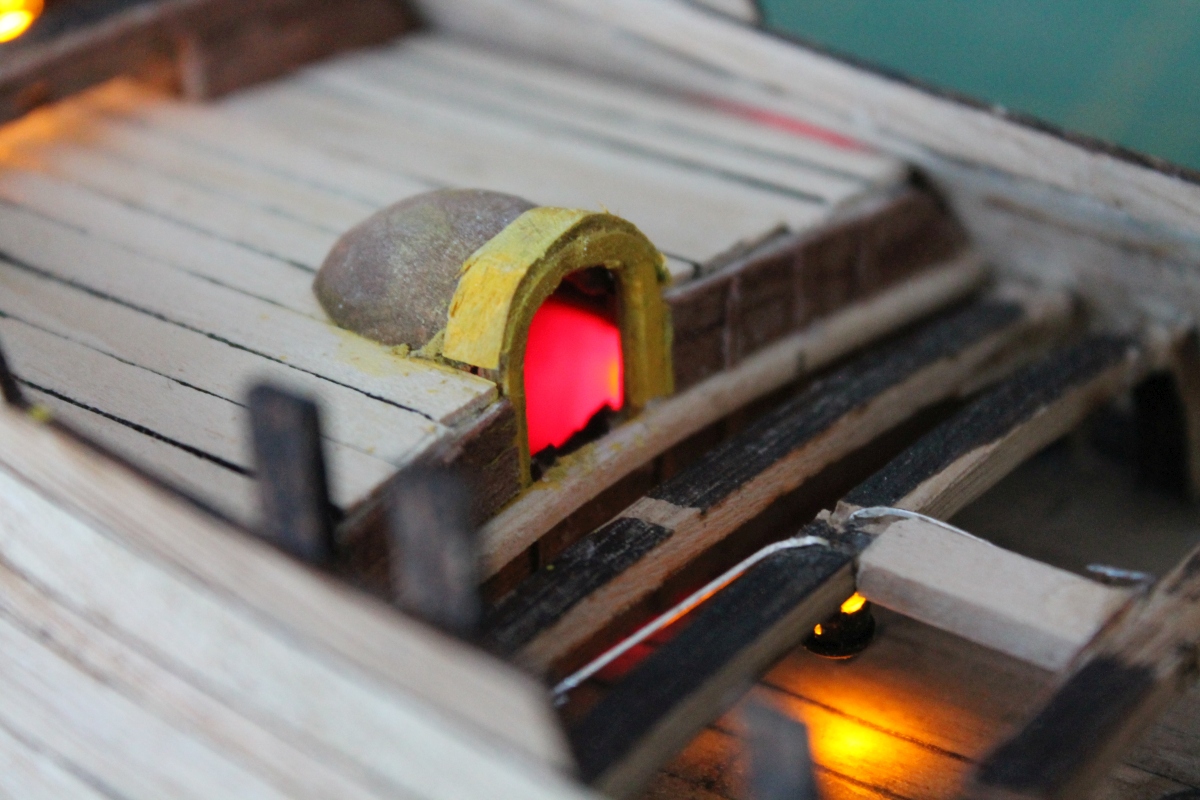
At least the lighting still works.
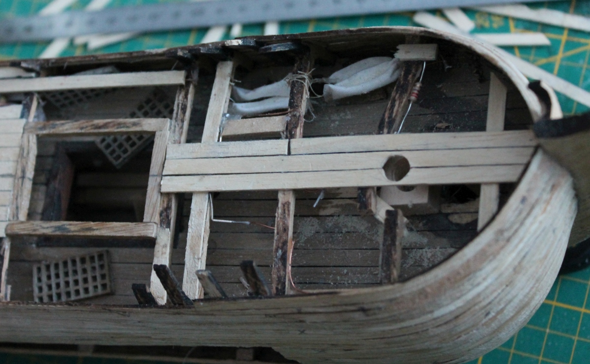
After planking, the foredeck looks like this. In front of the foremast there is now enough room for the beting etc. The bowsprit will rest tightly in the "hollow" diagonally left of the masthead. The back deck will be above. The position of the hollow is such that the bowsprit will get the right slope.
Now to the stern for a moment.
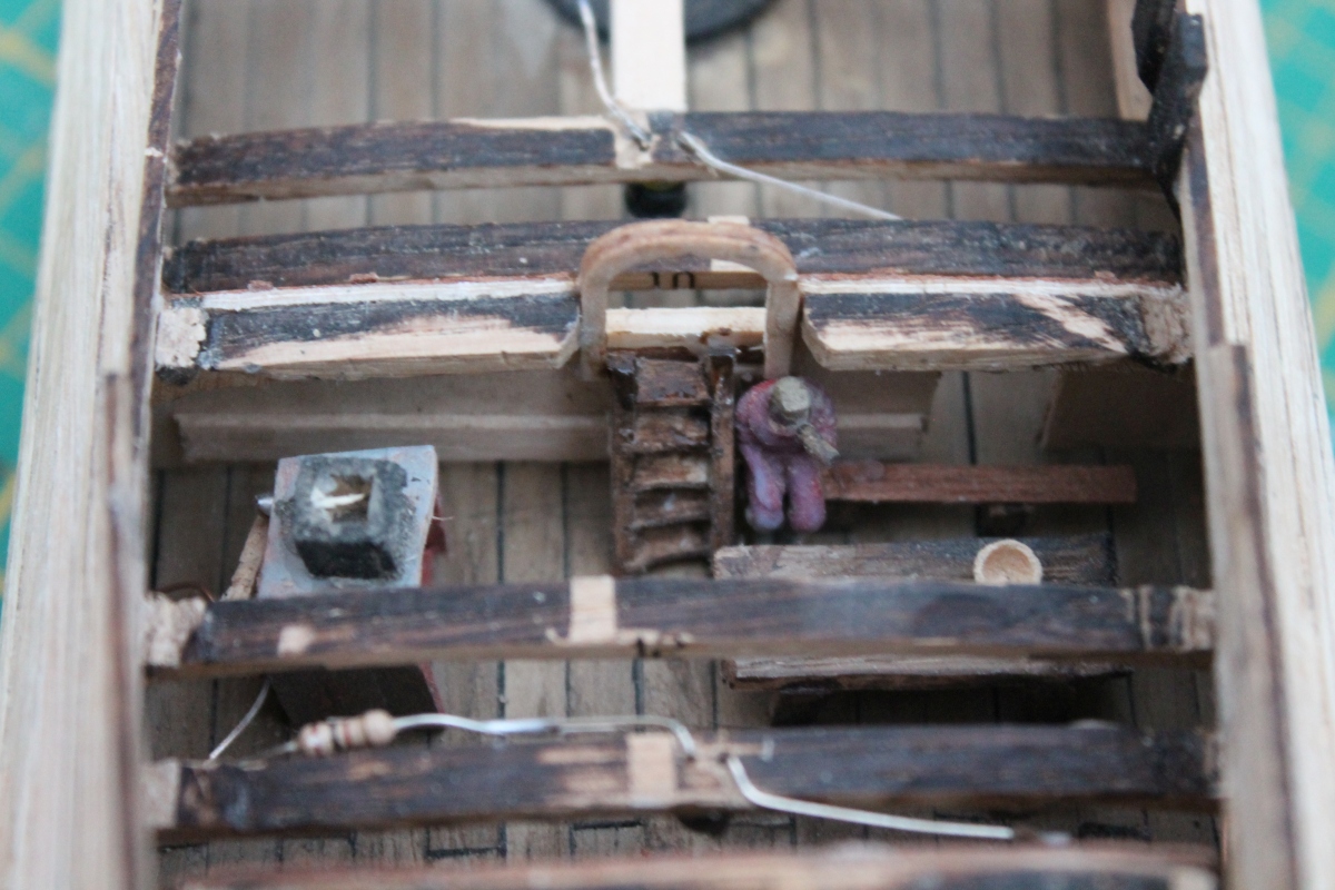
Here you can see the tiller running above the roof of the cabin. But it also runs under the floor of the cabin above it. So I had to make something that I could lay the floor of the cabin on.

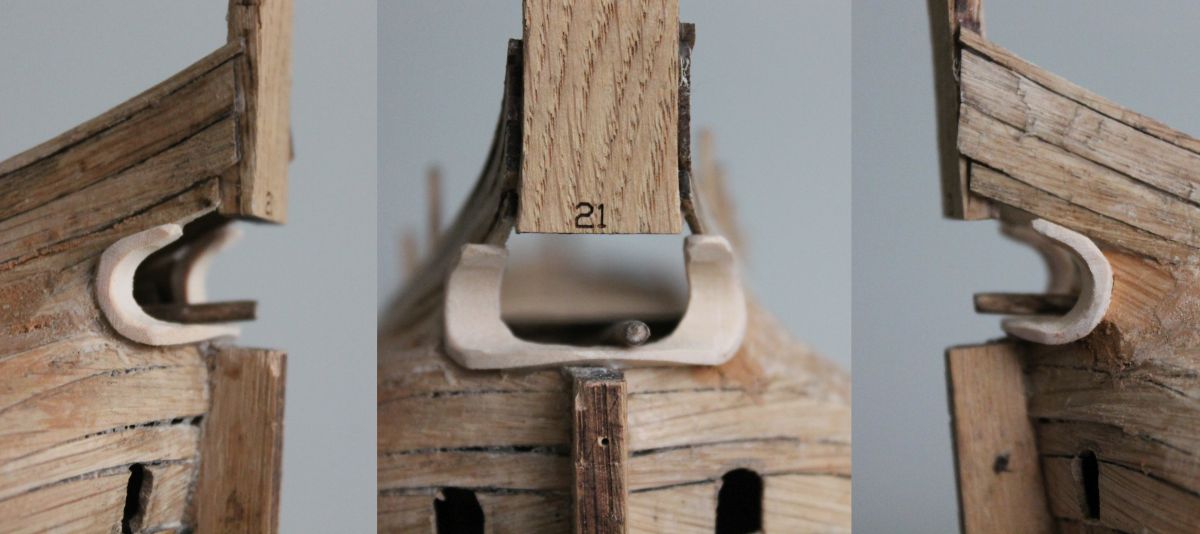
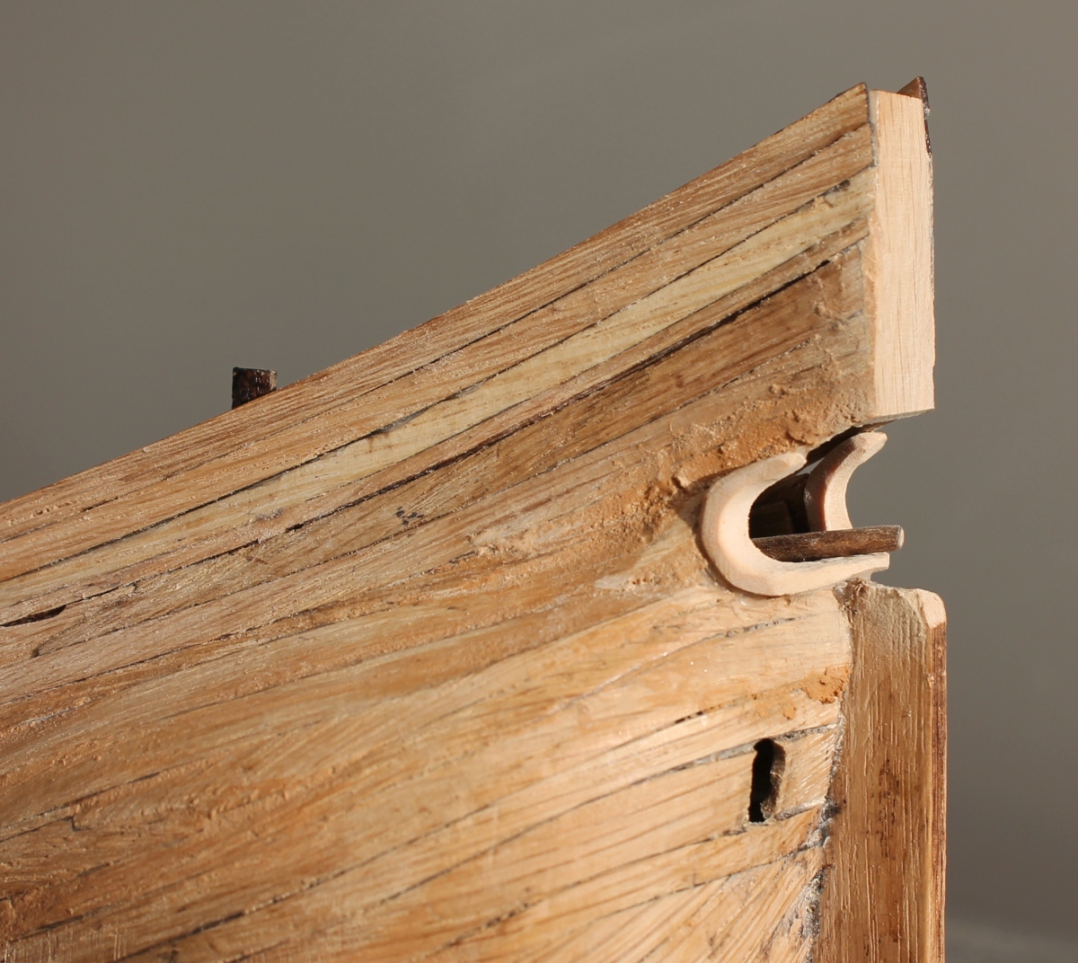
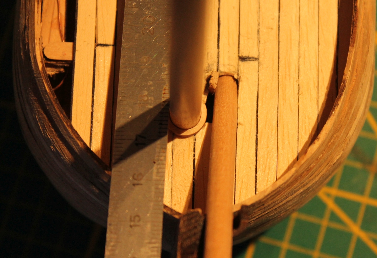
Under the heelboard I glued a batten which is also the top of the hemp hole.Below that a narrow batten that sticks out slightly inward, enough to lay the floor on.
The photo below shows that batten circled.
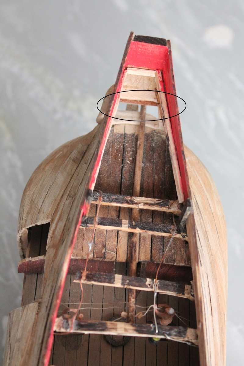
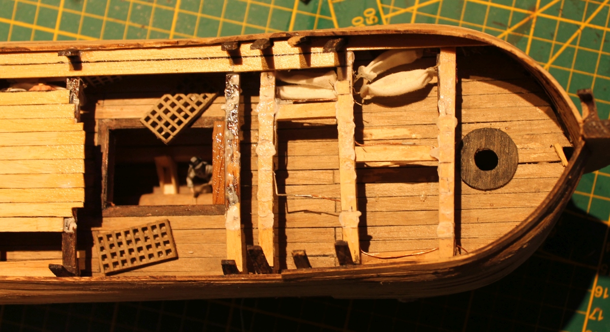
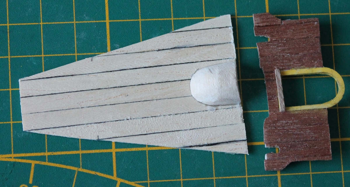
Also glued a couple of slats on the side for the floor. I made the floor by first gluing a few laths together and then fitting them in the right place. The result is shown in the next picture.
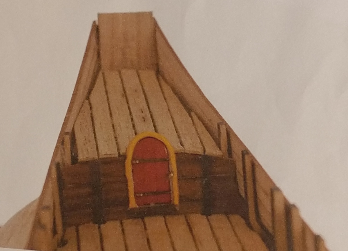
Now the roof of the hut and the bulkhead with access door in front of it.
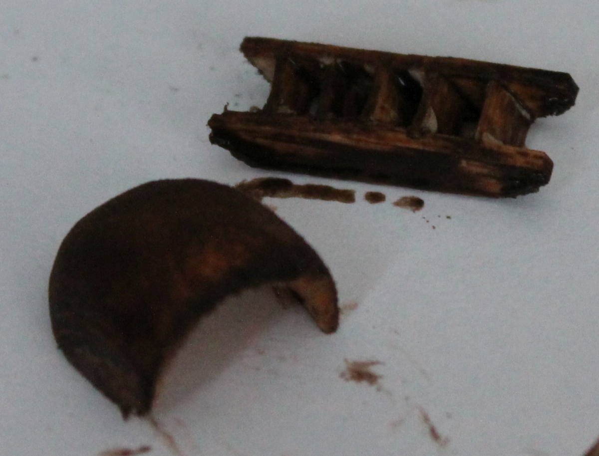
But first make the hood for the door. This is from a piece of 10x15 lime wood.
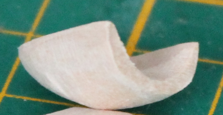
It's also hollowed out at the bottom because the door will be kept open so you can see inside the hut. That's why it also needed a floor.
Like the floor, I also made the roof separate from the model, just like the front. The space under the door in the front is made a little narrower because that is where the tiller runs under it. Wiring runs through the slots on the outside edges.
And after placement and two more decks it looks like this. Also already made a start with the railing.
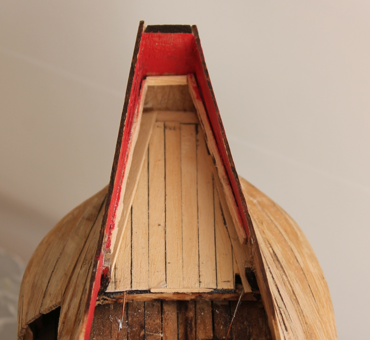
Clearly you can see inside the hut. There is no lighting there.
The whole ship now looks like this.
Finally, a view through the hemp hole. Above it is the cabin floor and below it is the cabin roof. And you can see the tiller running through the slot under the cabin door.
To be continued.
After the demolition work now rebuilding. The foremast had to be moved back a bit. The grommet in the upper deck led the mast to a mast foot on the keel. That could not be used now. Neither could the grommet through the deck. So I glued a block, with a hole for the mast, to the deck where the mast should now be. Of course, that had to be right under a deck beam with some wiring. I was able to cut that through and place it at a slight angle with a splice underneath to the other piece. So the foremast rests now on the deck and no longer on the keel.
I have also now patched the hatch, unfortunately slightly larger than the hatch below but that is not very noticeable.
At least the lighting still works.
After planking, the foredeck looks like this. In front of the foremast there is now enough room for the beting etc. The bowsprit will rest tightly in the "hollow" diagonally left of the masthead. The back deck will be above. The position of the hollow is such that the bowsprit will get the right slope.
Now to the stern for a moment.
Here you can see the tiller running above the roof of the cabin. But it also runs under the floor of the cabin above it. So I had to make something that I could lay the floor of the cabin on.
Under the heelboard I glued a batten which is also the top of the hemp hole.Below that a narrow batten that sticks out slightly inward, enough to lay the floor on.
The photo below shows that batten circled.
Also glued a couple of slats on the side for the floor. I made the floor by first gluing a few laths together and then fitting them in the right place. The result is shown in the next picture.
Now the roof of the hut and the bulkhead with access door in front of it.
But first make the hood for the door. This is from a piece of 10x15 lime wood.
It's also hollowed out at the bottom because the door will be kept open so you can see inside the hut. That's why it also needed a floor.
Like the floor, I also made the roof separate from the model, just like the front. The space under the door in the front is made a little narrower because that is where the tiller runs under it. Wiring runs through the slots on the outside edges.
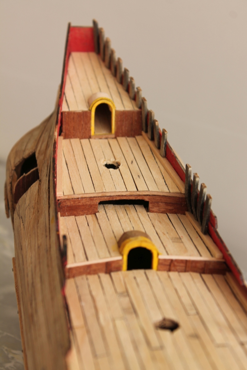
And after placement and two more decks it looks like this. Also already made a start with the railing.
Clearly you can see inside the hut. There is no lighting there.
The whole ship now looks like this.
Finally, a view through the hemp hole. Above it is the cabin floor and below it is the cabin roof. And you can see the tiller running through the slot under the cabin door.
To be continued.
Last edited:
- Joined
- Jan 9, 2020
- Messages
- 10,693
- Points
- 938

Jan, I take my hat off (petje af) to you with this build. That transom must be the most difficult one in model shipbuilding - period! I shouldn't be thinking about building new models at all, but this is a challenge that I would like to accept at some stage. I am just not sure that my choice will be oak. When all is said and done (and despite my WB2 in oak), I definitely prefer Kolderstok's walnut.
- Joined
- Apr 10, 2020
- Messages
- 146
- Points
- 213
Thank you Heinrich. Oak is a hard type of wood. But when wet you can form it, with heat, rather easily in almost any curve you want. But when dry in a not correct bend you cannot bend it with force in the correct way. It is then hard again. Then you have to wet it again and correct with heat. That makes it work and time consuming. But oak is the historical correct type of wood.
- Joined
- Jan 9, 2020
- Messages
- 10,693
- Points
- 938
My WB2 is in oak so I am pretty familiar with its characteristics. I agree with you on the historical accuracy part, and I did not find the bending to be a problem either; my main gripes are the tendency to splinter (cutting the walnut results in very precise and clean edges) and the coarse grain. On the plus side, the oak sands into a beautiful, smooth finish, but overall, I just like the darker look of the walnut.Thank you Heinrich. Oak is a hard type of wood. But when wet you can form it, with heat, rather easily in almost any curve you want. But when dry in a not correct bend you cannot bend it with force in the correct way. It is then hard again. Then you have to wet it again and correct with heat. That makes it work and time consuming. But oak is the historical correct type of wood.
Hallo @DeedsVery interesting to see how you're progressing!
I'm from South Africa and did some research into the origin of my family - Marais. Charles Marais sailed on a dutch Fluytschip (Voorschoten) from Delftshaven, Holland on 31 December 1687 and arrived at Table Bay on 28 April 1688. Therefor this ship has some sentimental meaning to me. I was excited to see that there are sets being sold for building a fluytschip, however as I have no experience in model ship building, it looks like it would be an impossible task - at least for now. I'll start small and maybe one day be able to build this
Until then, I'll enjoy following your progress here.
Best of luck with the build!
")
we wish you all the BEST and a HAPPY BIRTHDAY

@janzwart - I hope it is ok for you to use your topic for the greetings?!?
- Joined
- Apr 10, 2020
- Messages
- 146
- Points
- 213
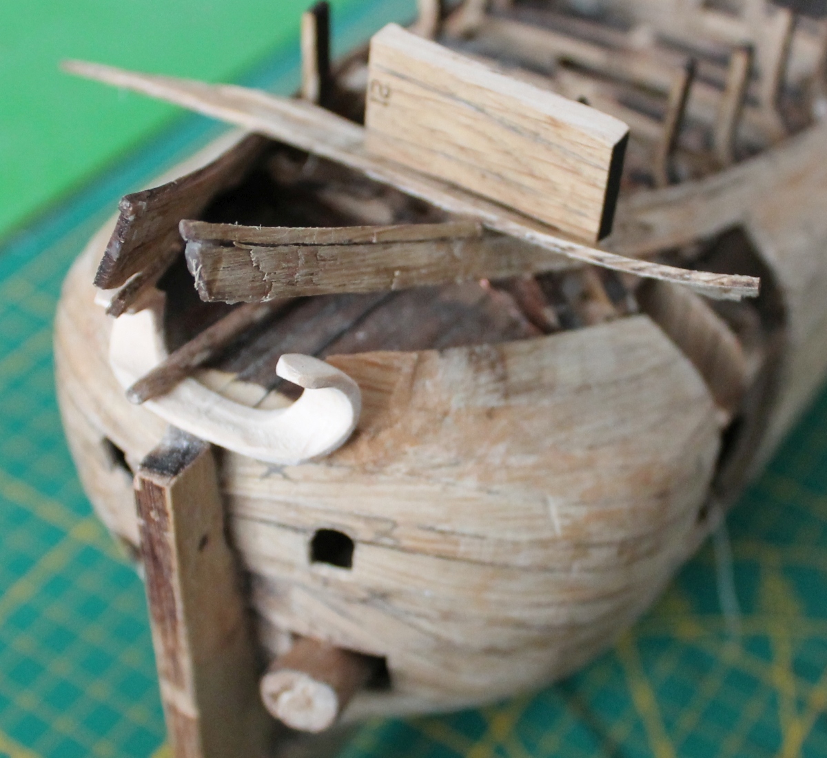
Update 27
First, I tackled theforedeck. By cutting the deck beams to size. I thickened the forwarddeck beam because the bowsprit actually goes right through it.
Theknight and nail bench are also ready to be installed.
I chose toplace the deck around them.
Unfortunately, I didn't take photos inbetween, only of the final result.
The bowsprit isalready in place and attached between the cleats on the deckbelow.
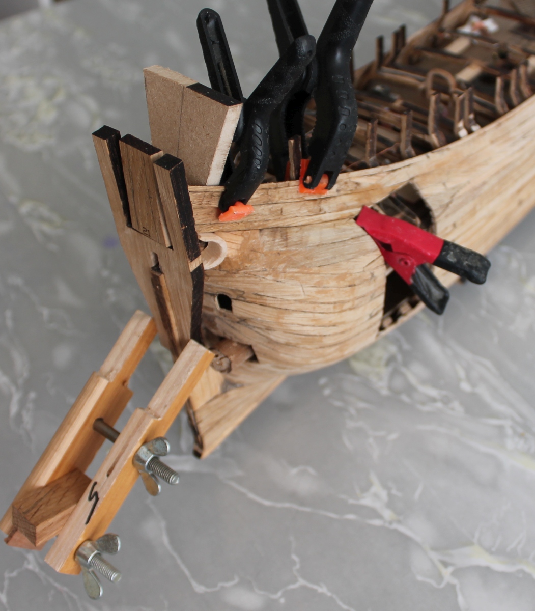
The next step is the pacing the wales. The first walewent fairly smoothly and is on acceptably. Except for a crack but youcan fill that.
I used a couple of nails to get the first wale onsmoothly. Then I thought it would be nice to nail down the entirehull. As has been done by others. So that resulted in thefollowing:
This disappointed me, they look too coarseand conspicuous. So I decided to replace the nails with sate-prickdots. And that's what you get:
This will look familiarto a number of people.
Then the second wale. Fixing the ends witha nail is handy. But oak is much harder than lime so you have to tapharder. And that does not always go well.
Take a look:
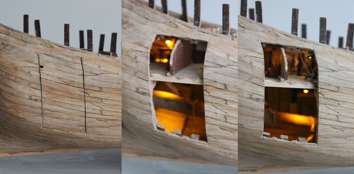
I had pre-drilled the wale butnot the plank underneath. It suddenly buckled inward. When pushing itback from the inside, it broke off completely, leaving a hole. I washoping to plug that with the wale and some malleable wood but thatwon't work. That it really is a hole you can also see when the lightsare on:
To make matters worse, I tapped the figurinethat was just behind this at the heads too. So I'll have to fiddlethat back in. But first, fix the hull under the wale after taking thewale off. Fortunately I had not yet mounted the framing of the cabinwindows.
To be continued.


- Joined
- Apr 10, 2020
- Messages
- 146
- Points
- 213
Update 28
Just a quick update onthe repair of the damage mentioned in previous update.
I stuck apiece of cardboard behind the hole by pulling it against the insideof the hole with a piece of string.

Behind thecardboard is a thick knot in the string, so I can pull the right partof the string.

On the front of the piece of cardboardsmeared quite a bit of wood glue, put it through the hole and pulledwith the rope against the inside of the model. After drying with theother side of the rope, pulled the rope out. Then filled the holewith kneadable wood and glued the mountain timber to it.
With thefollowing as a result:

to be continued
Translatedwith DeepL.com (free version)
Just a quick update onthe repair of the damage mentioned in previous update.
I stuck apiece of cardboard behind the hole by pulling it against the insideof the hole with a piece of string.
Behind thecardboard is a thick knot in the string, so I can pull the right partof the string.
On the front of the piece of cardboardsmeared quite a bit of wood glue, put it through the hole and pulledwith the rope against the inside of the model. After drying with theother side of the rope, pulled the rope out. Then filled the holewith kneadable wood and glued the mountain timber to it.
With thefollowing as a result:
to be continued
Translatedwith DeepL.com (free version)
- Joined
- Jan 9, 2020
- Messages
- 10,693
- Points
- 938
After Pandora ...But in retrospect, I think the difficulty of this kit should then have been rated 7 stars.
... and grained wood, out of scale (my observation)That break of the wood is exactly why I don't like oak - the brittleness and splintering.
")