-

Win a Free Custom Engraved Brass Coin!!!
As a way to introduce our brass coins to the community, we will raffle off a free coin during the month of August. Follow link ABOVE for instructions for entering.
-

PRE-ORDER SHIPS IN SCALE TODAY!
The beloved Ships in Scale Magazine is back and charting a new course for 2026!
Discover new skills, new techniques, and new inspirations in every issue.
NOTE THAT OUR FIRST ISSUE WILL BE JAN/FEB 2026
You are using an out of date browser. It may not display this or other websites correctly.
You should upgrade or use an alternative browser.
You should upgrade or use an alternative browser.
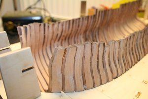
It will be some time until you see the frames next, so here all of them outside the jig.
Good to see, that the laser marks I used for the fairing fits realy good
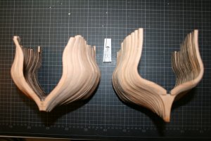
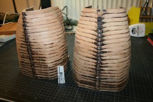
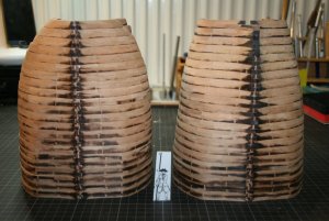
In the meantime I am already working on the pieces of the stem, but there are several hours more work to do, until I am able to show the progress.
Good to see, that the laser marks I used for the fairing fits realy good


In the meantime I am already working on the pieces of the stem, but there are several hours more work to do, until I am able to show the progress.
Last edited:
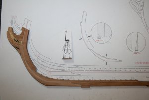
Working on the part of the stem I have to fix small wooden parts to chisel or sand them in order that the different parts fit together.
I remembered a small toll I bought years ago and use this for holding small parts during working on them.
I think ithe hand vice is from Amati but I am not sure. It is very helpfull tool. Highly recommended.
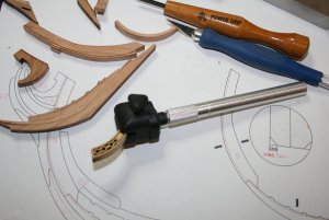
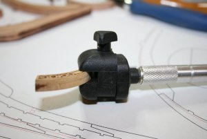
I would be interested which tools you have and use for holding small parts, hand tools and / or maybe fixed tools on the work desk?
I remembered a small toll I bought years ago and use this for holding small parts during working on them.
I think ithe hand vice is from Amati but I am not sure. It is very helpfull tool. Highly recommended.


I would be interested which tools you have and use for holding small parts, hand tools and / or maybe fixed tools on the work desk?
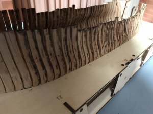
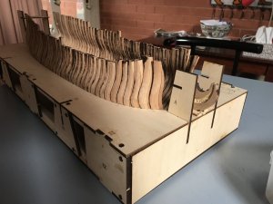
Hi Uwek, good work and interesting in that you have the laser cut beak decorative insert. Mine is a carved boxwood version. Another difference is the fit of the ribs in the cradle. Mine fit more snuggly right up to the edges of the cradle perhaps because I did not cut the futtocks down. And your futtocks gaps are far neater than mine. As for tools I use a variety of mismatched clamps, various hobby knives, some Permagrit files and other very cheap ones and a Proxxon vise which I have not used yet. I tend to work everything by hand. I wish I had proper workspace as it is tiresome getting everything ready then having to clean up after I finish working.


Last edited:
Hi Uwek, good work and interesting in that you have the laser cut beak decorative insert. Mine is a carved boxwood version. Another difference is the fit of the ribs in the cradle. Mine fit more snuggly right up to the edges of the cradle perhaps because I did not cut the futtocks down. And your futtocks gaps are far neater than mine.........
Thank you for showing. It is good often to compare the work and see how another modeler solved or did something. As usual we have to make during modeling everytime some small or bigger decisions, and these decisions you have to follow.
- the decorative insert (you will see in short time in a following post how it looks like) is realy a laser cut part (two halfs glued together). I got this element in the spare-parts delivery from Max, due to the fact, that the original boxwood version was not good. So it seems, that this is a small change in the kit and I received the "newest" version.
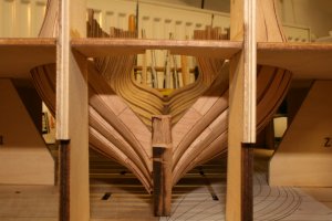
- You are right with your frames / ribs fitting in the jig / cradle -> You have later on enough material for sanding and final adjusting and I have to be much more carefull with outside sanding. On the other hand I have more meat inside.
So it could be at the end, that my Salamandre is a little bit to small in the outside dimensions, and maybe you have some small gaps when you come to the interieur.
The time will show us ........
Nevertheless it makes a lot of fun to make such a POF ship
PS: Are your frames / ribs already fixed to the keel? Mine not
Hi Uwek, no the ribs are yet attached to the keel. Need to do more sanding and fitting. I don’t think I will have this part of the build complete for at least a few more weeks. I have to say this is so far is a very enjoyable kit. So much different to POB and so many more complexitities. The work itself is not difficult but there is so much thinking required. Unique also in that the kit maker keeps the kit in perpetual evolution with ongoing changes and improvements.
.......... I have to say this is so far is a very enjoyable kit. So much different to POB and so many more complexitities. The work itself is not difficult but there is so much thinking required. ........
Yes, I agree and I can show it with the next photos, especially the complexity of all the parts fitting together so at the end it is one ship model.
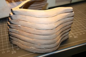
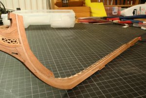
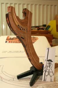
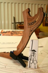
I finaly finished the stern construction, not finally sanded, but I want to show it to you.
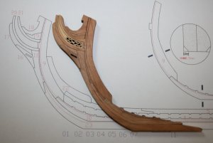
These are only 11 elements, and due to the fact, that the laser cutted boards have only half of the thickness every element is a sandwich of two twin laser cutted parts. So 22 wooden parts and I needed appr. 12 hours to come to this status......mainly to adjust the parts to get sharp joints
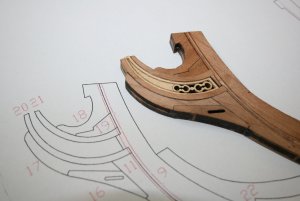
In the joints I put black paper (35g/m2)
I have also learned a lot with this exercise during the 12 hours work..........
1) Most important is, that I learned, that such elements have two sides.
Means: you have a drawing, f.e. see the above photo, and you lay down, correct, sand meassure the wooden parts based on this drawing -> finally after some time the two parts on which you are working are fitting together -> you are happy.........BUT...... Turning the parts and looking from thw other side there is still a gap of some micrometers, and some micro can be (from the feeling) like a canyon......so once more adjusting.
Partly I used the thick glass plate which you know already from the frame construction. On the glass you can arrange the parts, hold them and turn the glass, so you can see with the same arrangment both sides.....
2) Another thing what I learned......use for these things water based wooden glue! I glued two pieces together and fixed it with clamps. After drying I realized, that the elements moved, so a gap was there (the clamps produced some sliding forces, or I made a mistake). I put the parts into water and after 10 minutes I could loose them without any damage......Puh
Here you can see the other side of the stern (related to the description what I learned in 1
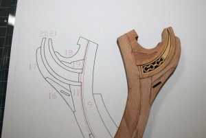
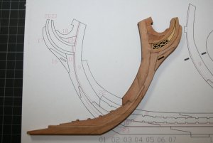
I think also this side is not so bad.....kit producers should think about to include an additional drawing exactly mirror-inverted. This would reduce the possibilty of mistakes and that models have a beauty and a beast side.
The next working steps are the final surface sanding and finalization of the rabbet
spectacular work Uwe.
Thank Uwek for your detailed report. I found the join of the base of keel( 23) to stem part(11) quite difficult to align due to the curve and varying thickness of the parts.
Correct.....and also together with part number 9. All three elements are defining the main curve of the stem and with this the length of the total ship.
Also in my kit, the parts had different thicknesses, multiplied by two (sandwhich).
So I had also to adjust the variable thickness with small parts of adhesive tapes.
The using of correct thick timber is in my opinion something in which the supplier should take more care.....
Many thanks also to @Brian077 for the comment
Hi Uwe, love your new sanding machine, at the moment I am using a converted drilling machine it does the job but I would also like to
purchase a sanding machine. Looking at your photos did I see you sanding the frames at the angle, at this moment I am sanding frames square
then using a DREMMEL with a sanding drum to blend in the frames.
purchase a sanding machine. Looking at your photos did I see you sanding the frames at the angle, at this moment I am sanding frames square
then using a DREMMEL with a sanding drum to blend in the frames.
Hi Uwe, love your new sanding machine, at the moment I am using a converted drilling machine it does the job but I would also like to
purchase a sanding machine. Looking at your photos did I see you sanding the frames at the angle, at this moment I am sanding frames square
then using a DREMMEL with a sanding drum to blend in the frames.
I love the machine too, not so much like my family, but close....- no, sorry this was joke.
The spindle sander is doing realy a good job, especially it is fastening the sanding procedure very much.
I think, that the big advantage to a sanding drum in drilling machine is, that the spindle is oszilating going up and down. So the sanding paper and the wood is not getting realy hot, although I push the timber with pressure against the spindle ( I am trying not to make too much pressure off course). Also the surface of the sanded wood is getting realy smooth. I am using grid 100, but there is also 120 and 150 available, so you can realy fine sanded surfaces.
With less or more or less no pressure it is absolutely possible to control the sanding at every stage, so within a very short time you can sand the frame at every angle. As you know, the surface of such a frame has to be adjusted from 0 to maybe 45 degrees with smooth and continuous change of the angle.....and this is absolutely possible with the spindle sander. I used in the past also a Proxxon for such works, but it is much easier, if you have the wood under control in your fingers and not the sanding tool. You have in this way a much better feeling........sorry for the lengthy explanations, you can see that I am realy happy that I made this investment........
BTW: many thanks for your interest
G'day Uwe
You should be a salesman for this spindle machine. The way you are talking about it,
Greg
You should be a salesman for this spindle machine. The way you are talking about it,
I might place an order to Santa.
Who know, I might be a good boy this year!
Havagoodone mateWho know, I might be a good boy this year!
Greg
Hi Uwe,
How deep is the rabbet?
How deep is the rabbet?
Hi Uwe,
How deep is the rabbet?
Mentioned in the CAF drawings, but as well in the ancre drawings from Boudriot 1,5 mm, so I tried to reach this depth
Mentioned in the CAF drawings, but as well in the ancre drawings from Boudriot 1,5 mm, so I tried to reach this depth
Then the frames fit on the keel inside the width of the rabbet? I’m having a hard time envisioning the assembly. Sorry if it’s an odd question.
Then the frames fit on the keel inside the width of the rabbet? I’m having a hard time envisioning the assembly. Sorry if it’s an odd question.
I will search for a good sketch to show how it works (or should work). Give some hours.....I can do this in the evening.....
My girls went for horse riding, so I was able to take a look earlier.
For a better explanation I made some photos of the Salamandre drawings from Jean Boudriot, showing at different frames the situation with the necessary cuts for the rabbet. Take a look at these drawings.....
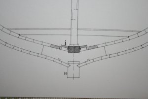
The first plank of the outside hull needs a rabbet in the keel, nothing else than a notch in the keel, longitudinal over the complete length of the ship.
With this construction, the shipwrights were able to produce a very strong connection between the stiff keel and the hull planking, as well a more watertight joint.
During sailing the timber of the keel was slightly bended, the keel also got slightly torsion. Without this rabbet connection, there would be often gaps which would be problematic.
The form of the rabbet is changing, depending on the location at the keel and the contact angle of the planks towards the keel.
See for this four different situations:
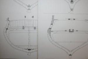
But also on top of the stem this rabbet was prepared, see herefore this drawing
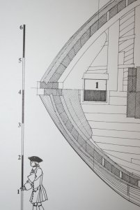
For a better explanation I made some photos of the Salamandre drawings from Jean Boudriot, showing at different frames the situation with the necessary cuts for the rabbet. Take a look at these drawings.....

The first plank of the outside hull needs a rabbet in the keel, nothing else than a notch in the keel, longitudinal over the complete length of the ship.
With this construction, the shipwrights were able to produce a very strong connection between the stiff keel and the hull planking, as well a more watertight joint.
During sailing the timber of the keel was slightly bended, the keel also got slightly torsion. Without this rabbet connection, there would be often gaps which would be problematic.
The form of the rabbet is changing, depending on the location at the keel and the contact angle of the planks towards the keel.
See for this four different situations:

But also on top of the stem this rabbet was prepared, see herefore this drawing

Hi Uwe,
A great explanation. I now understand what the rabbet is and why it is important. Another lesson learned.
A great explanation. I now understand what the rabbet is and why it is important. Another lesson learned.


