-

Win a Free Custom Engraved Brass Coin!!!
As a way to introduce our brass coins to the community, we will raffle off a free coin during the month of August. Follow link ABOVE for instructions for entering.
-

PRE-ORDER SHIPS IN SCALE TODAY!
The beloved Ships in Scale Magazine is back and charting a new course for 2026!
Discover new skills, new techniques, and new inspirations in every issue.
NOTE THAT OUR FIRST ISSUE WILL BE JAN/FEB 2026
- Home
- Forums
- Ships of Scale Group Builds and Projects
- Le Coureur 1776 1:48 PoF Group Build
- Le Coureur 1776 1:48 Group Build Logs
You are using an out of date browser. It may not display this or other websites correctly.
You should upgrade or use an alternative browser.
You should upgrade or use an alternative browser.
LE COUREUR - french Lugger 1776 - POF kit from CAF in 1:48 by Uwe
Does something like this (see below) is also happening to you sometimes?
Yesterday evening I was working / fairing some frames - and during this I was thinking about the postings here (post #42ff) in our forum.
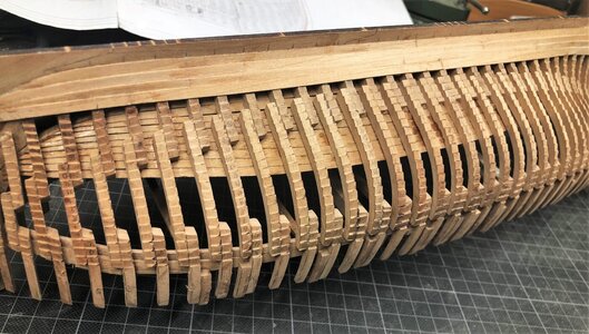
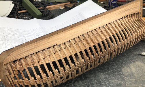
With this in mind I wanted to store the already prepared frames in two frame-"towers" with one from midship fore and one midship aft, in order also to see the "nice fairing" for the clinker planking.
And I got a shock

- it seemed that in direction aft the frames were all prepared wrong.
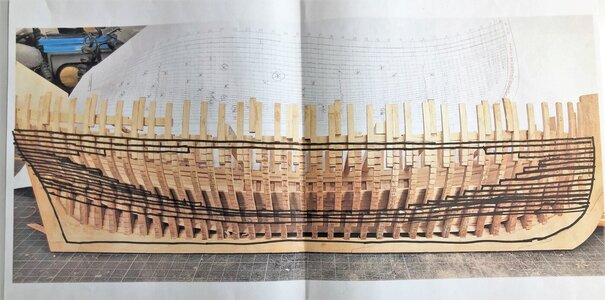
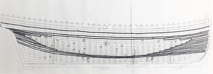
With these drawings (excerpts in the following) in mind, showing, that all floor timbers are into direction aft!
sideview and topview
View attachment 183933 View attachment 183934
and I got a 15 minutes "panic-attack"- I already wanted to write an e-mail to CAF asking for spare frames to make everything new....
How can this happen?
Why to me? Especially because at the same day I wrote such post like #42 !?!?
and I remembered also the last post by @Chello talking about the jig (#47) ..... best to check the frames inside the jig - a last prove before I write to Tom from CAF
So fast I removed the parts of the jig and stick some of the main parts dry together - putting the keel inside (it fitted well btw) and put all made frames on top of the keel inside the jig
AND:
Everything fine
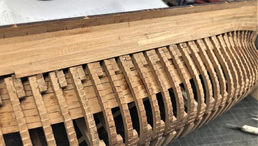
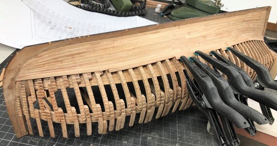
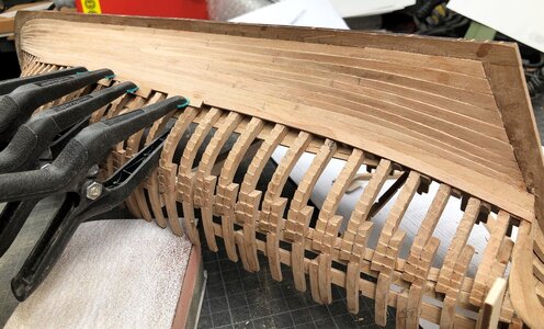
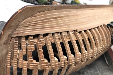
all frames are in the correct direction (floor timbers in direction aft) and all frames faired until now also correct - PUH
I do not know, why I was thinking somehow completely in the wrong direction - black out
So here some photos of yesterday late evening (for info: jig only partly dry installed and no accurate arrangement of the frames - pure check situation)
View attachment 183935
View attachment 183937
View attachment 183936
View attachment 183938
View attachment 183940
View attachment 183939
OMG
Once more many thanks for all your kind words and likes ...... great and many thanks
based on the information given in the manual it is important. that the two other horizontal parts (No. 12 and 13-2) and are in the correct level. therefore there are two small cantilever at the jig.... (marked with red arrow)
View attachment 188088
therefor I put back the structure into the jig and assembled it there
View attachment 188089
afterwards once more outside
View attachment 188091
View attachment 188090
according the drawing the top beam (part No. 13-1) has a slightly different angle
View attachment 188092
For the installation of the vertical elements
View attachment 188100
I fixed the keel with the stern structure "frame" upside down with a Proxxon vice - here the finished result
View attachment 188093
View attachment 188094
View attachment 188096
View attachment 188095
View attachment 188097
View attachment 188098
and back into the jig - be careful, but it is working...... and fits very well
View attachment 188099
Finally, after some thinking, small changes, re-open and re-assembling I am very happy with the result.
I described my way how I did it, so I am very interested, if there are other ways possible, so maybe you can show your experiences here or in your building logs .....
Many Thanks for your interest ..... to be continued .....
After just looking a a few pages of this amazing build log, I realize that “I don’t know nothing about model ship building”.
Somehow the planking work is getting more slow than before.....maybe I am a little bit bored,
but everything will end once.
I guess it will get newly interesting for me, when I reach the row of interrupted planking..... hope so
In the meantime I made a small test for the plank bolting. Somehow I would like to make the bolty like @Maarten is making on his amazing Alert,
But it looks like too much work for me
and
I am very happy and relaxed, because Jean Boudriot is not showing these bolts with washers etc.
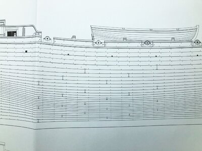
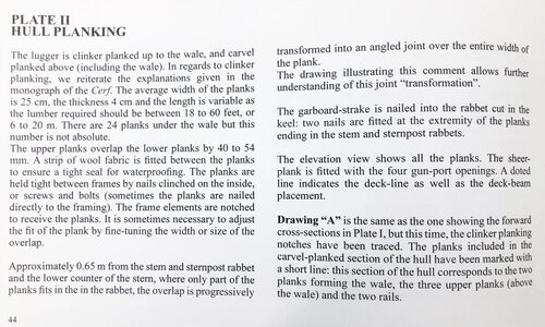
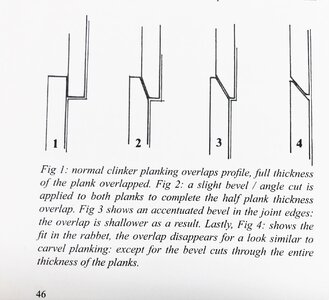
I tried to check this detail also with available photos in the web of scratch models of the Le Coureur or the Le Cerf to see how they made the clinker plank bolting, but I realized, that most or more or less all of them are not showing their clinker build hull in detail (or do not have the nailing or bolting shown) - seems, that this hull construction is not so easy and the results are maybe also not the best to show (but this is a pure guess by myself)
Here we can see brass bolts, a typical way french modelers are working
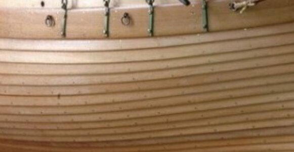
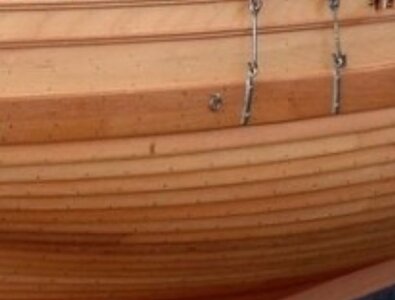
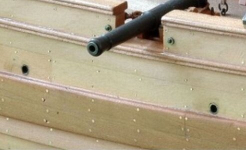
But
we have f.e. the very interesting building log of her Le Cerf scratch build made by Olha alias @shipphotographer.com with very good results
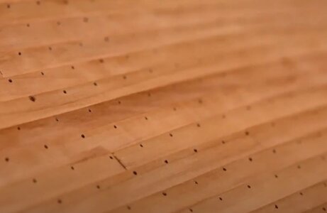
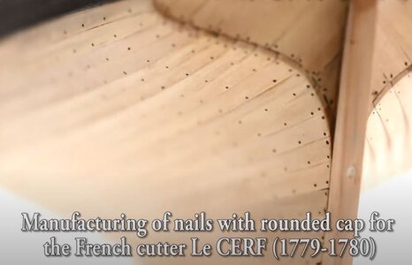
So I think, that I will do the bolting of the hull planking in the typical "french way", so I made a small test planking
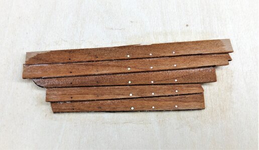
On the left two rows only with pre drilled holes, in the center one row with brass nails diameter 0,7mm and on the right two rows with copper nails 0,6mm
For the photo I made the planks wet, to get an impression, how it will look like at the end after oiling the hull
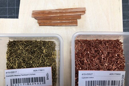
I am expecting in the next days a delivery of copper nails with only diameter 0,5mm
I think it will be at the end the 0,5 or 0,6 copper nails
but everything will end once.
I guess it will get newly interesting for me, when I reach the row of interrupted planking..... hope so
In the meantime I made a small test for the plank bolting. Somehow I would like to make the bolty like @Maarten is making on his amazing Alert,
Hms Alert by Maarten [COMPLETED BUILD]
After the lower transome parts dried the PS side is sanded to a flat surface. Next the PS wale is recolored with ecoline. Now I will prepare the planking above the wale. This planking will be yellow ocre, I color again with ink, dark yellow ecoline. The ink will keep the woodgrain visible...
shipsofscale.com
But it looks like too much work for me
and
I am very happy and relaxed, because Jean Boudriot is not showing these bolts with washers etc.


I tried to check this detail also with available photos in the web of scratch models of the Le Coureur or the Le Cerf to see how they made the clinker plank bolting, but I realized, that most or more or less all of them are not showing their clinker build hull in detail (or do not have the nailing or bolting shown) - seems, that this hull construction is not so easy and the results are maybe also not the best to show (but this is a pure guess by myself)
Here we can see brass bolts, a typical way french modelers are working


But
we have f.e. the very interesting building log of her Le Cerf scratch build made by Olha alias @shipphotographer.com with very good results


French cutter Le Cerf (1779-1780) - Scratch build 1:48 or just a DEER...
The La_Cerf's keel was laid in my shipyard in June 2014. In AutoCad I drew the bulkheads with steps in them for the clinker planking, which speeded up the planking with narrowing only in the bow and stern. To provide a larger area of adhesion, the spaces in the stern and the bow are filled with...
shipsofscale.com
So I think, that I will do the bolting of the hull planking in the typical "french way", so I made a small test planking
On the left two rows only with pre drilled holes, in the center one row with brass nails diameter 0,7mm and on the right two rows with copper nails 0,6mm
For the photo I made the planks wet, to get an impression, how it will look like at the end after oiling the hull


I am expecting in the next days a delivery of copper nails with only diameter 0,5mm
I think it will be at the end the 0,5 or 0,6 copper nails
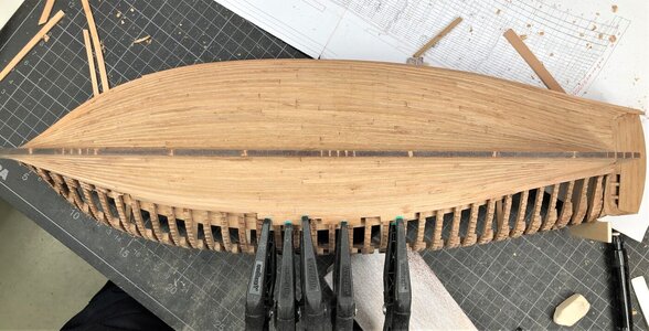
...the slow you go, the far you can reach! Great progress, Uwe!AS mentioned already I am making very small steps with the planking of the second side
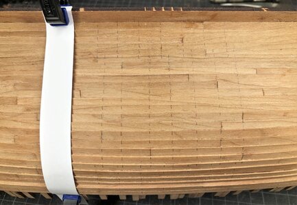
Step by step ..... and soon it will be necessary to mark the locations of the nailing of the planks
So I tried fastly this way with a cardboard - I made ist fast, so not completely accurate, but it would work
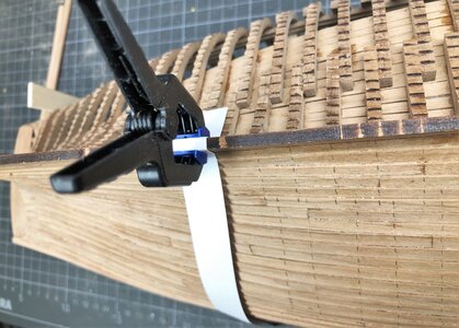
I have to think further about alternatives ..... so if you have an idea, please do not hesitate
So I tried fastly this way with a cardboard - I made ist fast, so not completely accurate, but it would work


I have to think further about alternatives ..... so if you have an idea, please do not hesitate
Maybe scotch tape - it's transparent. Looking great. I haven't seen hull so difficult to plank. You've done excellent job.Step by step ..... and soon it will be necessary to mark the locations of the nailing of the planks
So I tried fastly this way with a cardboard - I made ist fast, so not completely accurate, but it would work
View attachment 210376
View attachment 210375
I have to think further about alternatives ..... so if you have an idea, please do not hesitate
Kurt Konrath
Kurt Konrath
Soon this will be complete and you will be ready to move to the next kit in the pile coming in.
I don't know if is distortion of the picture but to me it looks like at least 1 maybe 2 lines for the middle futtock is slightly off:
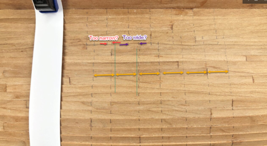
Unfortunately I do not have any really good ideas for alternative ways. Maybe for midships frames you could use a wider or more solid strip of paper and also make it 4 mm wider along the middle futtock?

Unfortunately I do not have any really good ideas for alternative ways. Maybe for midships frames you could use a wider or more solid strip of paper and also make it 4 mm wider along the middle futtock?
Last edited:
Dear UWEThese are the next information related to the jig given by the manual.
View attachment 185524 View attachment 185525
According Figure sketch No. 20 and 21 there are two options possible -
option 1 with closed side walls or option 2 with the open one´s with cut outs.
Due to the fact, that in my opinion it is very helpful to have a sideview possibility to check f.e. the connection between the individual frames with keel I decided to follow option 2
View attachment 185538
View attachment 185532
View attachment 185533
View attachment 185535
VERY IMPORTANT !!!
Take also a look in the manual No.2 inside the second box
View attachment 185526 View attachment 185527
View attachment 185528 View attachment 185529
And you realize, that for the future work you have to install "measuring sticks" through some holes in the side-walls which are defining the correct height of the internal structures......
You can see these prepared holes very good on this photo marked with the different arros (only a few are marked)
View attachment 185539
and you can easily see, that the holes are often located in the elements, which you remove for the before mentioned option 1 with open "windows".
Here one shown in closer view
View attachment 185530
So keep these parts and do not throw them away - You will need them later !!!!
View attachment 185531
Here you can see the topview with installed keel and the view through the window.
View attachment 185536
View attachment 185537
I'm building the Jig. Looks like your jig pictured above is just dry-fitted. I am not clear on one point: Did you glue the vertical parts A1-A7 to the slots in the B1-B2 base? I feel I need to either glue them to the base using a 90 degree metal square to insure they are perpendicular, or glue a square piece of wood 4-5mm/side to both sides of the the A to B joint. I suppose I could use short pieces of plastic 90 degree angle styrene. It seems to me that it would be ideal to be able to remove the A1-7 vertical pieces at a later phase in the build, using part of the jig to hold the keel in place.
Uwe:
Another question: who makes, or where can you get small copper nails ?
Alex R
Another question: who makes, or where can you get small copper nails ?
Alex R
Hope it is okay I post an input
Krick make small cubber-nails 0.5 x 10 mm. Guess many modelshops have them, or they can be bought for instance here: https://www.amazon.de/-/en/Copper-Nails-5x10-18-500Stk/dp/B0037YES18
Personally I did not glue any of the vertical jig walls to the baseplate.
Krick make small cubber-nails 0.5 x 10 mm. Guess many modelshops have them, or they can be bought for instance here: https://www.amazon.de/-/en/Copper-Nails-5x10-18-500Stk/dp/B0037YES18
Personally I did not glue any of the vertical jig walls to the baseplate.


