LE COUREUR - french Lugger 1776 - POF kit from CAF in 1:48 by Uwe

I don't know if is distortion of the picture but to me it looks like at least 1 maybe 2 lines for the middle futtock is slightly off:
View attachment 210468
Unfortunately I do not have any really good ideas for alternative ways. Maybe for midships frames you could use a wider or more solid strip of paper and also make it 4 mm wider along the middle futtock?
You recognized these mistakes correctly -as I amnetioned before, it was only a fast try if it is in general working.
and I realized, that in principle it is working
I am using a strip of paper to trace lines as I go. Running it over shorter distances greatly minimizes distortion, as the curve of the planks makes the paper twist.
correct, or also like
Maybe scotch tape - it's transparent. Looking great. I haven't seen hull so difficult to plank. You've done excellent job.
it will be possible

The first try I have to remove the pencil lines (obliterate is correct term, or?) and have to make it much more accurate

I have a small laser and will try it also with a "hanging" hull - this will be my weekend trial ;)
 
Dear UWE
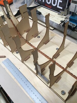
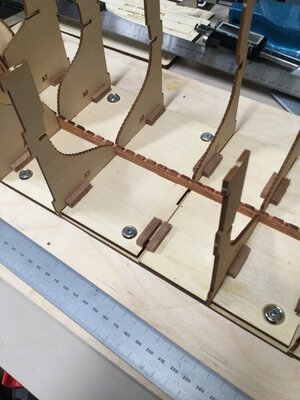
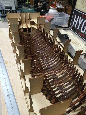
I'm building the Jig. Looks like your jig pictured above is just dry-fitted. I am not clear on one point: Did you glue the vertical parts A1-A7 to the slots in the B1-B2 base? I feel I need to either glue them to the base using a 90 degree metal square to insure they are perpendicular, or glue a square piece of wood 4-5mm/side to both sides of the the A to B joint. I suppose I could use short pieces of plastic 90 degree angle styrene. It seems to me that it would be ideal to be able to remove the A1-7 vertical pieces at a later phase in the build, using part of the jig to hold the keel in place.
Hallo,
in the beginning and visible in several photos of my building log, the jig was really only dry fitted, but definitely before I started to install the frames on top of the keel I fixed all of these "A"-type parts to the base.

Partly you can realize the glue in the wood edges
IMG-5256.jpg IMG-5258.jpg

In my opinion, it was not so extremely important, that they are exactly in 90°. I think most important is only that they are keeping the outside elements D1 and D2 correct, so that C1 and C2 are in the correct height.
Due to the fact, that during the installation of the frames you do not need these teeth in the jig, and partly bringing maybe more problems these jig elements "A" (with the height of the frames sitting directly on top of "A"), they could look also like this
IMG_5996a1.jpg

after fixing the inner planking and clamps at the frames, you will not need the jig any more, maybe only as a basis like this one (also only dryfitted at this stage
IMG-5260.jpg
 
Uwe:
Another question: who makes, or where can you get small copper nails ?
Alex R
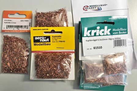
I bought mine at Modellbau Planet in Germany


They are using the same photo from krick like shown in the amazon link by @PoulD , but Modellbau Planet offers the same nails for appr. half of the price from amazon.......

If you want to order some of these nails, write a short mail to Mrs. Trip, a very nice and helpful lady, to mail@modellbau-planet.de and send regards from Mr. Karl from Vienna ...... I just ordered some more thousands of nails (1 bag has 500) from her.....

Do not underestimate the number of nails you will need:

This small ship Le Coureur has 25 planks with 38 frames and 2 hull sides -> 1.900 nails !!!! (and holes)

Nails will cost more than wire, but it is much easier to handle in my opinion:
predrilling with 0,5 - nail with 0,6 and a small hammer so the nail is pressed for 2 or 3mm inside the wood - cut the rest and sand (or burr like @Maarten is doing) the outer part.
I have a pliers or nipper, which is cutting directly at the contact to the wood, so only very small sanding necessary. The coppernail is very soft, so sanding is no problem at all.....
 
Uwe
Thank you for the advice and the link to Ms Trip. I will order at least 2500 copper nails.
My solution is below. I glued 4x4mm square pieces to each side of the A 1-7 pieces to keep them 90 degrees, but the A pieces can be removed. I only lightly glued the stem and stern pieces A8, A9,to the base, but also put square pieces:
10B9E796-3876-4CCD-9D5F-E370CC2542F5.jpeg

"A" pieces can be easily removed but are kept at 90 degrees when inserted.
4E084BEA-9BCA-4137-BD43-5EC28E448D9D.jpeg
 
Uwe
Thank you for the advice and the link to Ms Trip. I will order at least 2500 copper nails.
My solution is below. I glued 4x4mm square pieces to each side of the A 1-7 pieces to keep them 90 degrees, but the A pieces can be removed. I only lightly glued the stem and stern pieces A8, A9,to the base, but also put square pieces:
View attachment 210662

"A" pieces can be easily removed but are kept at 90 degrees when inserted.
View attachment 210663
This is looking very good !!!

Before you close the jig finally, you could check the sit of the frames, which are exactly at the location over the "A"-parts. I guess it can help later on, that these frames are correct in the height!
IMG-4529aa1.jpg

IMG-4534aa1.jpg
 
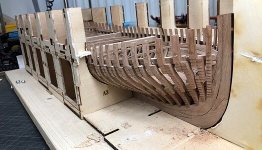
Frames 7 to 34 (not beveled yet....) are dry-fitted to the berth and fit very well. The remaining frames do not fit into the B1-2 notches because they are not beveled yet.
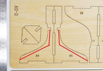
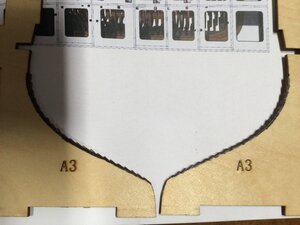
Also, the frames that sit on the "A" supports do not fit (sit) as well as the others because of the serrations in the A supports. I think I will sand-off the serrations on all the "A" pieces 1-7, since the serrations on parts A1-7 really serve no purpose that I can see..This will allow all the frames to sit perfectly on the keel. Any opinions on this ?
Once all the frames are beveled, and the A supports don't have serrations, all the frames should fit perfectly on the notches on B1-2.
We'll see (said a blind man)
Alex R

965EBD86-51EC-42CB-A726-75DB37BBA05E.jpeg
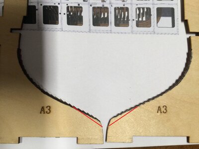
I plan to sand off the serrations in black....on pieces A1-7 Opinions ???
4D82871F-680C-4D74-BE03-F33625378D63.jpeg
 
Very good progress
on my model I had only to remove or better sand down at the lower part of the "A"-sheets, appr. like marked on this photo
4D82871F-680C-4D74-BE03-F33625378D63.jpg
This was enough and the frames were sitting correctly on the keel. But also according my opinion (and experience of this build) these "serrations" technically not necessary.

You wrote:
Once all the frames are beveled, and the A supports don't have serrations, all the frames should fit perfectly on the notches on B1-2.

Yes, the frames should fit as much as possible into the notches, but have to sit in the same time in the correct height on top of the keel.
Any mistakes here you will realize later on during the planking, when you have to adjust the serrations on the frames, so that the planks are sitting correctly in x-y-z directions

BTW: Please do not forget, and it would be very good, that you also actualize your building log
 
Hi Alex and Uwe!
Yesterday evening I sat at my workbench and having the same progress as you have Alex, I had the same thoughts!
So I also will sand away the serrations.
I am having troubles with sanding the frames, because the dust is very aggressive to my hands and face.
Have to use gloves and FFP2 mask and therefore progress is very slowly.
 
Hi Uwe,

Great work as allways :).

Most simple way of marking the spots for the nails is to do it while laying the planks. Mark the frames after every row of planks and you know you have the correct center.
Many Thanks for your comment - and you are right
On the second side I am doing it already in this way
 
Many Many friends for all your kind words and all the Likes received - Great motivation

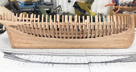
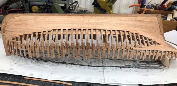
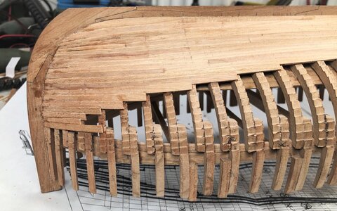
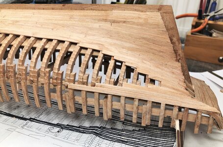
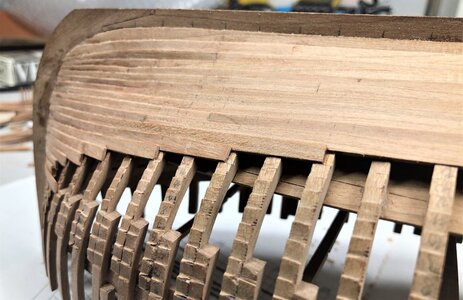
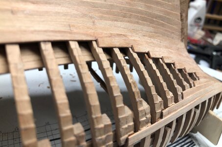
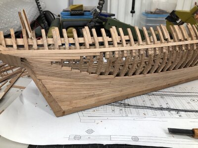
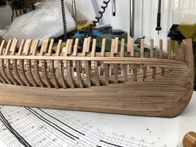
During the weekend I had the possibility to work some hours more on the planking of the second side of the hull.
And step by step it can be visible, how the "window" will look like. I hope to finalize the normal planking in the coming two or three days and after the installation of the wales I can start with the nailing. I am waiting for the delivery of 0,5mm copper nails (as an alternative to the used 0,6mm of my test planks) and also the special burr from company Bush which was introduced by our friend @Maarten in his amazing Alert group building log.
When the material arrive (in next days), I will make a test and will decide, if my nails will have to be bigger and get some washer, or smaller diameter and "normal" head

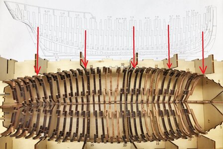
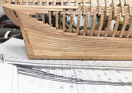
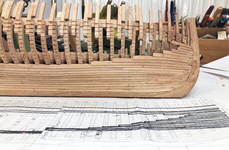
But for now a small update of the actual status of yesterday evening - you will see, that there are some smaller defferences between my plan laying under the hull and the reality -> these changes in the planking pattern were based on fast decisions caused by personal taste during the construction progress.
As usual more photos than really necessary ;)

IMG-5646.jpg

IMG-5644.jpg

IMG-5645.jpg

IMG-5649.jpg

IMG-5647.jpg

IMG-5648.jpg

IMG-5651.jpg

IMG-5650.jpg

Many Thanks for your interest ..... to be continued
 
Looks great as always. I quite like this version of the planking. This will probably be my direction as well.
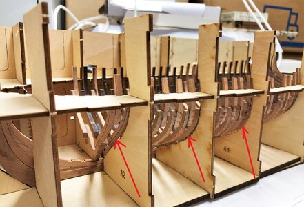
When I finished the planking, I will dryfit once more the interior walls and decks, and make some photos. So we can see the effect, and you could adjust some details of the planking where necessary
 
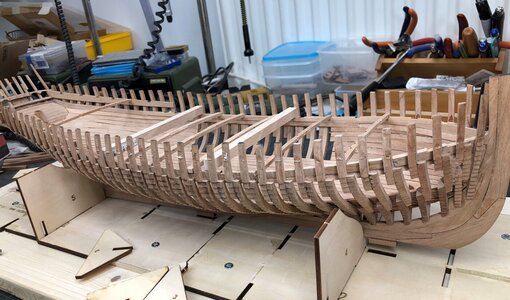
Yesterday I was able to finalize the complete planking under the wales up to planking row 3

IMG-5666.jpg

IMG-5667.jpg

So the next will be the installation of the wales, the final cleaning of the small rests of char on the visible areas of the frames and the nailing of the planks
 
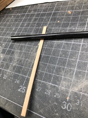
Small tip for the planking works

-> I call it "Dry Bending"

If you do not want to water or steam the planks for bending, these planks can also be bend (for 90% of the cases on this ship model dry.

I show in principle this way I did on most of my planks for the Le Coureur.

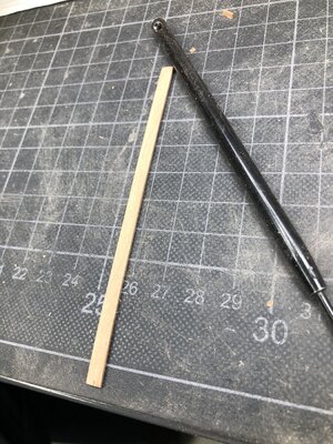
Here you see a plank streight and only sanded on top of a hobby / cutting mat - The black rod next to the plank is a small metalic chisel
IMG-5661.jpg

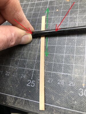
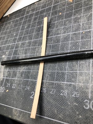
Now take the rod with two hands (for the photo I needed the right one for making the photo) and run up and down (green arros) above the plank with relatively high pressure (red arrows)
IMG-5662a.jpg

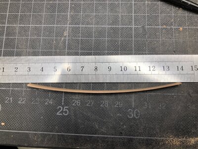
after some run you will realize, that the plank is starting to bend
IMG-5663.jpg

IMG-5664.jpg

The reduction of the thickness is minimal - the bending is suitable for most areas of this model
IMG-5665.jpg
 
Back
Top