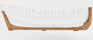
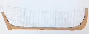
LE COUREUR - french Lugger 1776 - POF kit from CAF in 1:48 by Uwe

Uwek

Administrator
Staff member
Administrator
Forum Moderator
Joined
Dec 25, 2017
Messages
30,718
Points
1,238

Location
Vienna, Austria
Today I want to start my building log of the Le Coureur

But before I want to summarize the existing information available here on SOS

A detailed Kit Review you can find here:


The description of the kit development here:


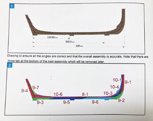
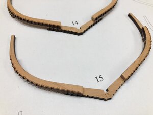
Also in the beginning I want to show an excerpt of the manual, which is my opinion a very important information

IMG-4421.jpg

Caf Model
For those who want to know more about her, you can purchase a detailed monograph of her directly from Ancre.
The monograph is available in French, English and Italian.


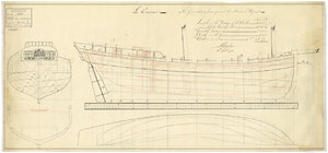
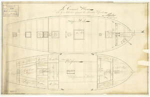
There are two contemporary drawings available from NMM dated 18 September 1778

j0873.jpg
Scale: 1:48. A plan showing the body plan with stern board and decoration and name on stern counter, sheer lines with inboard detail modifications proposed in green ink, longitudinal half-breadth, and midship section showing the clinker framing, for 'Coureur' (1778), a captured French lugger, as modified to an 8-gun Schooner. Signed by John Henslow [Master Shipwright, Plymouth Dockyard, 1775-1784; later Surveyor of the Navy, 1784-1806].
j0874.jpg
Scale: 1:48. A plan showing the upper deck, and fore and aft platforms, with proposed modifications in green, for 'Coureur' (1778), a captured French lugger, as modified to an 8-gun Schooner. Signed by John Henslow [Master Shipwright, Plymouth Dockyard, 1775-1784; later Surveyor of the Navy, 1784-1806].


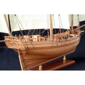
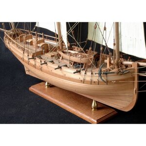
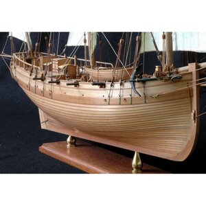
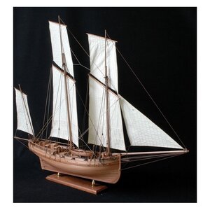
There is a beautiful model shown on the web-page from ancre, a model built by Gerard Chatainier and I hope, that my model will (somehow) looking like this one - you get a very good impression of the project
monographie-du-coureur-lougre-1776 (1).jpg

monographie-du-coureur-lougre-1776 (2).jpg monographie-du-coureur-lougre-1776 (3).jpg monographie-du-coureur-lougre-1776.jpg

So enough with the theory - let me start now
 
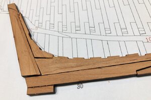
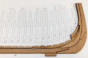
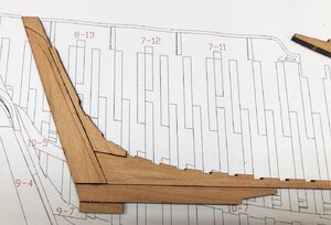
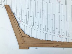
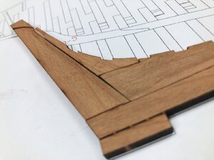
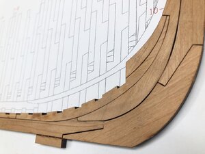
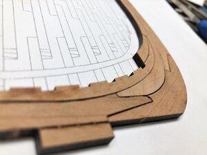
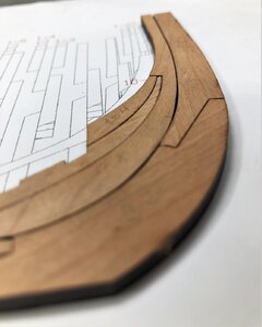
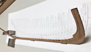
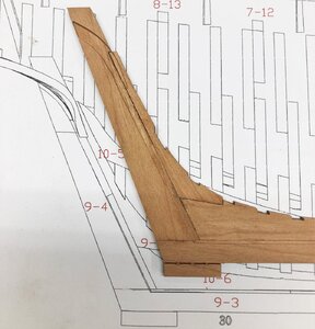
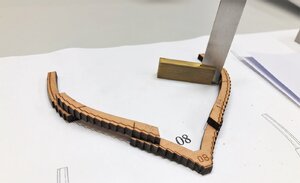
Today I removed the parts of the keel from the sheets 9 and 10 (shown in sketch 2), based on the manual instruction.
I wanted to see, how good the part are prepared, timber quality, laser cut and cnc milling...... I wanted to touch the kit parts

IMG-4422.jpg

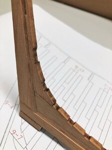
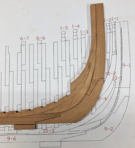
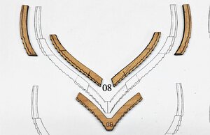
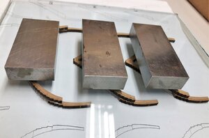
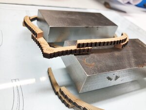
Here you see the parts, laying on the CAF drawing. cut out but without any cleaning, char removal or sanding
IMG-4418.jpg

IMG-44191.jpg

IMG-4420.jpg

I am very impressed about the quality - here the fitting of the stern post parts with some small cleaning - already much much better
IMG-4423.jpg

To be continued ..... asap
 
Today I removed the parts of the keel from the sheets 9 and 10 (shown in sketch 2), based on the manual instruction.
I wanted to see, how good the part are prepared, timber quality, laser cut and cnc milling...... I wanted to touch the kit parts

View attachment 181379

Here you see the parts, laying on the CAF drawing. cut out but without any cleaning, char removal or sanding
View attachment 181377

View attachment 181381

View attachment 181378

I am very impressed about the quality - here the fitting of the stern post parts with some small cleaning - already much much better
View attachment 181380

To be continued ..... asap
I came to the same conclusion as Uwe in relation to how well the pieces fitted straight out of the frames. I suppose the challenge is not to remove too much material when sanding off the laser char. One of the pieces need to be assembled using its “flip” side which has some laser discolouration but this is easily sanded off with 400 grit sandpaper.
 
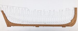
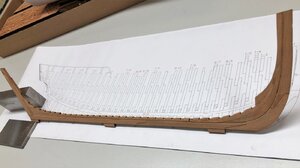
Today I am able to show the keel elements after the sanding and preparation by removing char

Here is the complete result - dry fitted
IMG-4426.jpg

IMG-4425.jpg

IMG-4427.jpg

IMG-4430.jpg

IMG-4428.jpg

IMG-4429.jpg

and after fixing with wood glue
IMG-4437.jpg

IMG-4431.jpg

IMG-4432.jpg

IMG-4434.jpg

IMG-4435.jpg

IMG-4433.jpg

IMG-4436.jpg

It is really a pleasure to work with these parts and elements - good quality timber, precise laser cut and very good fitting - GREAT and a lot of fun
 
Today I am able to show the keel elements after the sanding and preparation by removing char

Here is the complete result - dry fitted
View attachment 181500

View attachment 181499

View attachment 181501

View attachment 181504

View attachment 181502

View attachment 181503

and after fixing with wood glue
View attachment 181511

View attachment 181505

View attachment 181506

View attachment 181508

View attachment 181509

View attachment 181507

View attachment 181510

It is really a pleasure to work with these parts and elements - good quality timber, precise laser cut and very good fitting - GREAT and a lot of fun
Thank you for leading the way Uwe, I hope to follow suit today.
Question, did you assemble the jig already or are you waiting for the keel to be finished as one of the jig parts functions as a template for the stern .
 
Thank you for leading the way Uwe, I hope to follow suit today.
Question, did you assemble the jig already or are you waiting for the keel to be finished as one of the jig parts functions as a template for the stern .
No, until now not. I started with keel and will try also some frames to prepare. Afterwards the jig.....
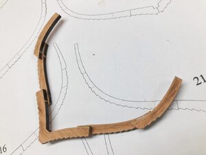
 
One Comment related to the drawings.....
I realized, that it will be helpful and for the frames necessary, that you use the rolled drawings as templates - with gluing the parts together on top of the drawings.
So therefore I recommend, that you make in the beginning a copy of these rolled drawings - could be helpful to have a spare drawing if you need .......
 
After the keel the next step also shown in the manual are the frames.

Due to the fact, that the Le Coureur had a clinkered planked hull, the frames of this kit are very special made.
I think the frame construction and accurate preparation are one of the challenges of this kit.

a1cbf89fd9.jpg

The manual mentions to start with a typical frame, so I followed the suggestion and started with frame No.8 - I think this is also a very good choice in order to understand the principle construction of the frames.
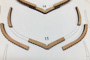
Here you can see the parts of one frame - only five parts
Very good to see are the "teeth" prepared by laser cut and the related beveling lines (for fairing) marked also by the laserIMG-4439.jpg

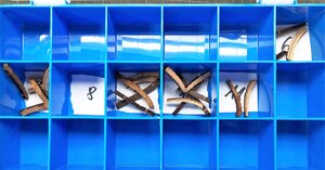
Due to the fact, that the floor timbers are marked with numbers - so later on you can not mix the frames up, when you want to install them on the correct place on the keel. I started in the beginning to write the correct frame number on every other part, but realized, that this will be not necessary, if you carefully separate the parts of every single frame - I am using for this this kind of box
IMG-4455.jpg

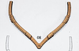
The first dry-fit of the five parts of frame 8 - you have to carefully place the futtock part following exactly the beveling line marked on the floor timber and the top timber - not so easy, so this is no work for stress or hurry up
IMG-4440.jpg

fitting well
IMG-4441.jpg

on the right side not so good......
IMG-4444.jpg

IMG-4442.jpg
IMG-4443.jpg

In the manual it is shown to use a square to find the accurate correct location (or good eyes (better ONE eye) in bird view. ;)
IMG-4447.jpg

Due to the fact, that the char removal of the face sides will be later on (after a frame is finished) not so easy - I am sanding the faces before with my disc sander - Do not forget this!
IMG-4457.jpg

Here you can see three frames glued together, secured and loaded with a glass plate and some steel weights
IMG-4458.jpg

The first frame No 8 glued together
IMG-4460.jpg

IMG-4461.jpg

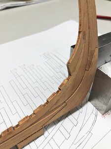
starting to bevel the frame - only to try how this work is going ........
IMG-4462.jpg

Question:

For me, it is still not clear when is the best time to bevel / fair the frames........
1) To fair before gluing the parts of one frame together - than maybe only some smaller corrections afterwards
or
2) Glue the parts together and fair them afterwards - like I did in the first frame
or
3) Only light fairing on the area where the frame is connected with the temporary jig and fair the frames just vefore the planking installation....

I am open for suggestions and opinions ....... ?????

Or maybe @CAFmodel can give a good advise ????
 
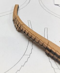
did you fair with a file? Step for step? Or did you use one oft your power tools? I count roughly 25 steps per side per frame ... must take a hell lot of time doing it with a (needle) file and not "harm" them?
Yes you are right - with a very fine needle file
This is what I tried until now, but you are also correct with the necessary time needed for this. And I finalized not one area until now.......
I really assume, that I will need half an hour up to one hour per frame (midship less - others more)
So it will be very time consuming.........
and I am a little bit afraid, that after finishing the single frames, it could maybe not fit with the planking when the farmes are installed on the keel.

So I can only repeat the word by CAF written in the instruction:

DOUBLE CHECK THAT THE ASSEMBLY IS ACCURATE AND WE CAN NOT STRESS THIS ENOUGH.
ANY ERROR IN SHAPE WILL GREATLY EFFECT SUBSEQUENT WORK.
 
BTW: I am not afraid, that the laser marks could produce mistakes in the overall assembly - everything is 3D-designed so the parts will fit also in combination with the planking, jig etc.
-> Here I am pretty sure, mistakes can only produced by the modeler not working precise enough
They say there is strength in tranquility
 
UWE DO YOU HAVE A LINK FOR THESE FILES. GOD BLESS STAY SAFE YOU AND YOURS DON
The manufacturer is PFERD and the productline is Corradi - needlefiles (available in different grades (0, 1 or 2 -> 2 is very fine)
You have to search if they are in your country available - I bought them via amazon.de (Germany)
 
yes, these handy needle files are my prefered tools! and they are my oldest tools still in use!
It really pays off to buy quality - and to take care for them ;)
absolutely .
The price of one set is 60 or 70 Euro - I ordered the finest ones with Hieb 2 - based on the needs of the Le Coureur I just ordered now also Hieb 0 and Hieb1
 
absolutely .
The price of one set is 60 or 70 Euro - I ordered the finest ones with Hieb 2 - based on the needs of the Le Coureur I just ordered now also Hieb 0 and Hieb1
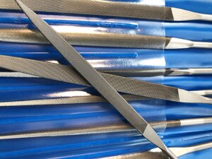
after one day the new needle-file sets arrived already

so I have no argument any more......
IMG-4479.jpg
 
With building the different frames, some things are getting more and more clear, especially the working steps and methods which work well and which one not.....
and I want to share my experience working on the CAF Le Coureur with you.

Without fixing the floor timber and the top timber on the base, it was not easy to get the futtock really exact on the correct place.
So my hint for everybody building this kit:

Fix the floor timber and the top timber with some small drops of glue on the drawing / copy - a small one is realy enough, some pressure and some seconds later they are fixed and the parts will not move any more. Later on before installation on the keel the sides of the frames have to be sanded anyhow in order to remove the light laser marks.
IMG-4469.jpg

Here the floor timber and the two top timbers are fixed and the futtocks are prepared
IMG-4470.jpg

some further glue on the contact area
IMG-4471.jpg

and now only the futtocks have to be aligned correctly
IMG-4472.jpg
 
Last edited:
Back
Top