Le Fleuron 1729 - 64 Gun Ship PoB Scratch Build in 1:48 - (Ancre Monograph-J. Boudriot/G. Delacroix)

Thanks to everyone for the input, comments, and likes.

So when I finished the first round of tests, I realized I've learned quite a bit about the process, and from a couple of mistakes made in critical areas, specifically the final etching step. As the oldest of 8 kids, I was the first to get a bicycle when I was a young boy. But, with 8 kids, my parents could not afford "training wheels" for my bicycle. So wanting so badly to ride my new bike, I fell, got up, fell, got up, Band-Aids on my knees, fell, etc. The point is, I never quit. I sure didn't have "training wheels" for this process.

So I will be making some adjustments in metal thickness and final etching time. Along with rectifying the mistakes, I will attempt to improve the final products.

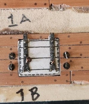
But ever curious, I decided to take the sub-par parts created and see how bad they looked if I used them in their current state on the ship. Not on the ship, but on a test panel created for the "treenail test" I conducted a few weeks ago.

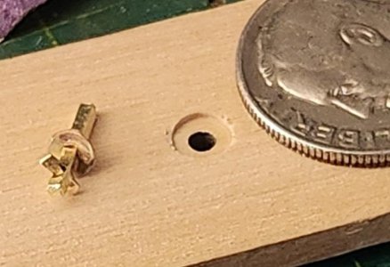
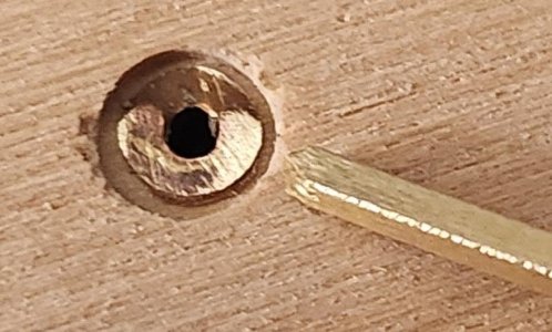
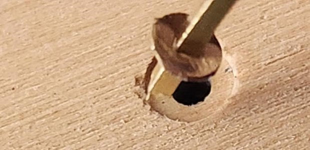
For the bolt washers, I created a simple jig to hold the washer in place so the square bolt could be pressed through it. This is the first time I've worked with parts this small. The square bolt is 0.85mm in diameter, and the washer is just 0.2mm thick and very fragile. The gun port hinges are 0.35mm thick.

Some photos on the bolt, washers, and stop pin construction.
thumbnail (14).jpgthumbnail (13).jpg
thumbnail (3).jpg
Another lesson learned during this exercise: in the future, I will dry fit the components, disassemble and blacken them individually. In this case, I assembled and blackened them as a unit, which made it very difficult to buff and remove the residual blackening agent. With all the tools I have, I have none small enough to do that.

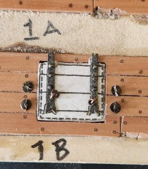
The test is to see what the finished parts look like in scale, using sub-par components. If they are close, then the thought is that improvements in the quality of the components may suffice in creating a finished product for the gun ports.


thumbnail (17).jpg
thumbnail (16).jpg

Observations:
Under magnification, the parts are borderline. With that said, if I can improve them a bit, I think they would be acceptable for use.
  • The washers are slightly out of scale, being a bit too large in their diameter. Their size will be reduced.
  • The hinge bolt holes will be moved a bit lower, especially the eyebolts holding the rings.
  • Hinge bolts are scaled well, but the heads of the bolts stand too proud. This cannot be seen very well in the photo, but from the side it is obvious.
I will repeat both sets of tests and perhaps even construct a finished gun port lid. If I can pull off improvements, great. If not, I will likely create the artwork and contract out the photo etching.

Once again, guys, I don't see this through the lens of success or failure. It is simply a feasibility test, and actually fun for me.

Thanks again for stopping by and providing your experienced input! Till next time...

Cheers!
 
This was a nice tutorial Ken, I always kind of wondered how photo etching was done.
Thanks Daniel. I always wondered about photo etching myself. It is a very interesting process, and the process I'm testing is pretty much the way all photo etching is done, albeit with different variables needed for the specific application. I think the modeling communities (scaled trains, aircraft, and now ships) have benefited from the evolution of technology, specifically the DIYers in the PCB fabrication area. For me, the learning continues. :)
 
Thanks to everyone for the input, comments, and likes.

So when I finished the first round of tests, I realized I've learned quite a bit about the process, and from a couple of mistakes made in critical areas, specifically the final etching step. As the oldest of 8 kids, I was the first to get a bicycle when I was a young boy. But, with 8 kids, my parents could not afford "training wheels" for my bicycle. So wanting so badly to ride my new bike, I fell, got up, fell, got up, Band-Aids on my knees, fell, etc. The point is, I never quit. I sure didn't have "training wheels" for this process.

So I will be making some adjustments in metal thickness and final etching time. Along with rectifying the mistakes, I will attempt to improve the final products.

But ever curious, I decided to take the sub-par parts created and see how bad they looked if I used them in their current state on the ship. Not on the ship, but on a test panel created for the "treenail test" I conducted a few weeks ago.

For the bolt washers, I created a simple jig to hold the washer in place so the square bolt could be pressed through it. This is the first time I've worked with parts this small. The square bolt is 0.85mm in diameter, and the washer is just 0.2mm thick and very fragile. The gun port hinges are 0.35mm thick.

Some photos on the bolt, washers, and stop pin construction.
View attachment 518320View attachment 518319
View attachment 518317
Another lesson learned during this exercise: in the future, I will dry fit the components, disassemble and blacken them individually. In this case, I assembled and blackened them as a unit, which made it very difficult to buff and remove the residual blackening agent. With all the tools I have, I have none small enough to do that.

The test is to see what the finished parts look like in scale, using sub-par components. If they are close, then the thought is that improvements in the quality of the components may suffice in creating a finished product for the gun ports.
View attachment 518323
View attachment 518322

Observations:
Under magnification, the parts are borderline. With that said, if I can improve them a bit, I think they would be acceptable for use.
  • The washers are slightly out of scale, being a bit too large in their diameter. Their size will be reduced.
  • The hinge bolt holes will be moved a bit lower, especially the eyebolts holding the rings.
  • Hinge bolts are scaled well, but the heads of the bolts stand too proud. This cannot be seen very well in the photo, but from the side it is obvious.
I will repeat both sets of tests and perhaps even construct a finished gun port lid. If I can pull off improvements, great. If not, I will likely create the artwork and contract out the photo etching.

Once again, guys, I don't see this through the lens of success or failure. It is simply a feasibility test, and actually fun for me.

Thanks again for stopping by and providing your experienced input! Till next time...

Cheers!
Great progress and nice tutorial. Will ya make the working hinges or?
 
What's interesting Ken is the trial hinges in all their variance or imperfections may very well reflect a true scaled handmade piece of port cover hardware; they certainly appear realistic.
 
Great progress and nice tutorial. Will ya make the working hinges or?
Thanks Jim. Yes, I will be soldering up working hinges. For these tests, I didn't create an actual gun port lid or working hinge as I was focused on the etching process. ;)
 
Photo Etching Part 2

The next step, building the UV Light Box used to expose the film. It is a DIY effort. Now I know when it comes to building things, my skills don't come close to the mad scientist skills possessed by my friend Stephan, I just hope my efforts produce something that works.

Materials

Ignore the glass dishes and photo roll (black tube). Also, not shown is the UV LED strips' hardware (in the box) and electrical connecting wires that run the series.
  • Bamboo box, only 3.5 inches deep, but I can always increase the distance of the lights from the prints manually.
  • Aluminum tape
  • 1/8in x 8.5in x 11in plywood
  • UV LED strips, with remote control dimming and timing, which I thought would come in handy, and at $16, I could not pass up.
  • LED strip connectors (I chose these to eliminate any need to solder)
View attachment 518003

First things first. Use the aluminum tape to cover the plywood, which provides some UV reflective value.
View attachment 518005
I then mapped out the LED strips and staggered each row to provide a little room when making connections. Since there were two power connectors were provided I decided to use each one to power only 1/2 the bank of LEDs, ensuring sufficient power to all LEDs.
View attachment 518007

Testing, 1, 2, 3. Oh, wait, I mean POWER UP! It's important to understand not to look directly into real UV light, as it most certainly can damage eyesight.

View attachment 518008.

In the box. The LED board is held in place using two large Velcro strips. I wanted the ability to remove if I had to work on it in the future. I almost grabbed the Hot Glue Gun...RedfaceROTF
View attachment 518010
Outside box, with power and controls.

View attachment 518009

Ok, now that the light box is ready, it's time to prep the test samples, bolt washers first. I take the two identical test pieces of artwork, tape the first one, printed side UP, to the desktop. Then its partner and place it on top of the first one, printed side DOWN. Then, using three small pieces of tape, tape the two pieces on three sides, only after I've ensured the registration marks are aligned. The fourth side remains open, forming a pocket. The brass test sheet is inserted into the pocket.

Note: The arrows below point out anomalies in the ink coverage on the artwork. This can happen during the printing process or, more likely in my case, when I inserted the brass sheet into the pocket, scraped the ink. In either case, these can be covered up with a black Sharpie, EZPZ.

View attachment 518219

To ensure all three elements remain in place, I create a sandwich with two pieces of Plexiglass being the "bread".
View attachment 518217

View attachment 518222

I've read so many tutorials online, each having its own set of variables when it comes to this step. There are really three variables that directly affect the exposure.
  • The power of the LEDs or light
  • The distance of the sample from the light source
  • The time of exposure
Being my first run, I had no point of reference. So I decided, based on everything I read, to create my own point of reference for the exposure step.
  • Full power of the UV LEDs
  • 5 inches of proximity from the sample
  • 6 minutes of exposure, each side
I did that for both samples and ended up pleased with the results of both. The exposed film seemed to take on a muted purple color after being cured, bolt washers below.
View attachment 518240

Tight, crisp lines. I'm :D.

Up next....

The Wash
Note: The final steps involve caustic chemical agents. I wear gloves, protective eyewear, and even an apron. While both of the agents I use, Sodium Hydroxide (Lye) and Ferric Chloride, are on the low end of the caustic spectrum, both will cause skin burns or serious eye damage. It's always slow and steady. I chose these two chemicals BECAUSE they are the milder choices. Other tutorials prefer other more caustic agents. The difference in the choices is straightforward. The more caustic the chemical agent, the faster the metal is etched, and the more harmful they are if mishandled. I can wait 1.5 hours for the final etching, compared to 15 minutes.


Ok, the "Wash" is the step that washes away the unexposed, uncured areas of the photo film. The first step is to remove the outside protective film that is still in place on BOTH sides of the brass sheet. BOTH sides, Einstein!!!! More on this later. :rolleyes:

Once the film is removed, a wash bath is created by combining Sodium Hydroxide and Demineralized/Distilled H2O. While many people online state the ratio does not have to be exact, once again, working with chemicals, I always start conservatively on the "mild" side, always with the option of strengthening the solution if it isn't as effective as expected.
View attachment 518221
My wash ratio was 5 grams of Sodium Hydroxide to 150 ml of distilled H2O. This worked fine. So after thoroughly mixing, I submerged both samples into the wash and let them sit for a minute. Then, with an old, soft, small paintbrush, I gently stroked the bass sheets for about 30 seconds. Looking carefully, you can see the film slowly being washed away, leaving the purple cured film.

After doing for both samples, both sides, they are removed from the wash and put into a container of distilled clear water, which stops the wash process.

My results were mixed, but valuable.
View attachment 518213

So, again, for the final etching step, every area where you can see brass, that metal will be etched away, the blue will remain and after a final wash, leave us with tiny identical parts, hopefully. At first glance, everything looks great, but....

View attachment 518216
The sprue connectors that the arrows point out have delaminated from the metal. I'm ok with this. The reason I'm conducting this test is to identify and resolve any issues before the real production runs.

So, I believe that there are a few reasons the cured film would delaminate from the brass.
  • The metal was not cleaned sufficiently, and dirt or debris prevented the film from adhering completely
  • The sprue connector was too thin to provide the same adhesion
  • The temperature of the lamination process was not hot enough to achieve the same
It could be all three. No worries here. It is not a deal breaker. Now, if 80% of the sprues did not adhere, I would have a big problem, but this one is manageable.
Next step...

Etching
Etching is the removal of the unprotected metal, leaving you with the areas that are protected by the cured photo film. The etching agent I used is Ferric Chloride, 40% solution, which I used straight out of the bottle. This is not some crazy caustic, like Fluoroantimonic acid. Still, I'm very careful. Again, I chose this agent to preserve safety over expedience.
View attachment 518220

Below you can see the "bolt washer" test plate in the Ferric Chloride solution, diluted. I later realized I needed to use it at full strength and adjusted. (Sorry, no photo). Ok, so the final results for the "bolt washers" test were compromised by my wandering mind. I referred to this earlier in the post, with the "Einstein" comment. When preparing the brass test sheet for washing, I forgot to remove one side of the protective film. It was still in place during the final etching, affecting the removal of metal. Instead of the etching taking place on both sides at the same time, resulting in the removal of metal uniformly, one side was protected from the etching agent, resulting in over-etching in some areas and not in others.

View attachment 518214

I had no predisposition for the outcome of this test. Success or failure, the truth lies in the feasibility. Can I use this process to create my own uniform, tiny, metal ship parts, or not?

Note: This is not the all-or-nothing solution. Keep in mind, I can still create the artwork and then send those Vector images to a 3rd party service that will create them for me. I can't remember who, Ondras or another master builder, does just this, measuring the value of time and effort. The only downside here is being at the mercy of the lead time of that company, which is not a big deal, as I can be working on many things while waiting.

Ok, after all the exposed metal is etched away, you are left with these parts, albeit covered in cured photo film, again, sorry, no photos.

So what is needed is a final wash, same as the first wash, just let them soak and brush away the film. It just takes about 7 minutes.

WARNING: The next photos are explicit and may be disturbing. Viewer discretion is advised!

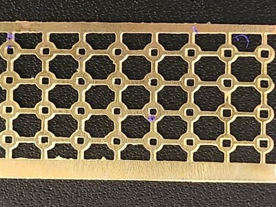
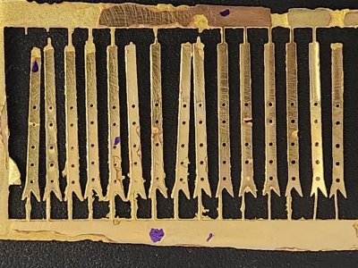
Gun port hinges.

Pros

  • All parts were fabricated, that's it.
Cons
  • Uneven etching
  • Side etching, resulting in rough edges, that will need to be worked (sanded, filed) to make smooth.
With these observations, it's important to note, the photo is magnified and the end result, with a little work, is acceptable, in my view on the ship with human eyesight.
View attachment 518228

Bolt Washers

Pros

  • Not many. Some washers turned out well, others not so much. Concern is the lack of uniformity of final product
Cons
  • Many, however, I cannot attest to the efficacy of this test as I screwed a few things up
Leaving the protective film was a biggie. Additionally, the sheet thickness being 0.2mm left me with little or no room for error.

View attachment 518229


So what now?

Observations
The process of photo etching metal, brass, or copper is feasible. I'm not at all discouraged by the results I achieved, knowing nothing. I honestly feel the shortcomings of the final product can be rectified with a little practice and honing down the variables.

The process, when first read or even first practiced, seems very involved, but actually, it is not. There are dependencies that need to be followed, but overall, it is very logical.

This exercise was eye-opening for me. I think my final decision as to whether I will photo etch my own parts or not will depend on whether the quality meets my expectations, on the ship, in scale, and not a magnified photo. The other option is outsourcing the actual process after creating the artwork. The last option seems very viable at the moment.

Before I make a decision, I will take it to the next step, once I'm bored of planking again. I will adjust the variables that I believe caused some issues and see if the final product is of a higher quality.

Secondly, I will take these parts I made and work a little bit with a file and sandpaper and see how they present in their application on the ship (test hull).

Thanks for looking in. Don't be discouraged, I'm not

Cheers
Brilliant tutorial Mr Hoss. Thoroughly enjoyed reading through. Now the objective is how to download it as an article with pictures included. Thank you that was extremely interesting. Cheers.
 
What's interesting Ken is the trial hinges in all their variance or imperfections may very well reflect a true scaled handmade piece of port cover hardware; they certainly appear realistic.
Hi Daniel, Yes, I agree, the scale of the hinges matches perfectly with the drawing, in scale. I could work with the hinges as they are produced. With that said, I will give my best in improving them. The scale of the washers is off as they are about 15% too large. I've prepped the brass sheets for the next run of tests. They have the photo resist film already applied and waiting in a dark box in the shop. I'm waiting for the standalone version of Adobe Illustrator, which is scheduled for delivery on Friday. I need to adjust the drawings, i.e., the bolt holes in the hinges need to be enlarged, just a bit. The first hinges' bolt holes were not etched all the way through and resulted in "bolt depressions" rather than bolt holes. I had to drill them through afterwards, although the depressions did help center the drill, I'd rather not drill anything.

I'm actually going to try and etch the bolts that are used with the washers and pins. It was very difficult to "put a punch mark" and drill that square wire when it's 0.8mm with a 0.3mm drill bit. :rolleyes: So I'm going to try and etch them with the holes in them. I am not as optimistic this will work. If it doesn't, I will add it to the professional outsourcing experts.

Great observations.

Thanks for following Daniel.
 
Brilliant tutorial Mr Hoss. Thoroughly enjoyed reading through. Now the objective is how to download it as an article with pictures included. Thank you that was extremely interesting. Cheers.
@ConsNZ, thank you for the complimentary words. To see the process, it seems very involved. I do think the process is logical, so once done once or twice, it's not a big deal at all. The current tests I've done to date required about a $95 investment. The quality missing in the final product does not discourage me as I believe it can be achieved with better technique on my part, which I will continue to work to improve it, at least a couple more rounds, as long as I see improvement.

With that said, if I cannot improve the quality to meet my expectations, "the juice is not worth the squeeze". Time a few more runs will tell.

Thanks for following along, my friend.
Cheers!
 
Back
Top