• LUCZORAMA SHIPWRECK SCAVENGER HUNT GIVEAWAY. 4 Weeks of Fun • 1 Legendary Prize ((OcCre’s Fram Ship)) • Global Crew Welcome!
    **VIEW THREAD HERE**

Le Fleuron 1729 - 64 Gun Ship PoB Scratch Build in 1:48 - (Ancre Monograph-J. Boudriot/G. Delacroix)

Thank you all for the warm welcome back, taking the time to visit, and all the likes.

A small update. I started planking the hull, between first and second gun decks, only to realize I'm human and to be one is to err. :rolleyes: After planking the bottom three of four runs of planks, I realized that the gun port cutouts on the bottom plank were incorrect, as they accounted for the sills of the ports extending to the outer edge of the external planks. I decided not to follow this standard for cosmetic reasons. The result was that the cutout was vertically too large. So off it came, and I'm now in the process of reconfiguring.

So as we do, when we get stuck, we take a small step of testing the plank fasteners' appearance, treenails, and bolts. French 74s of the period typically had a combination of treenails and iron bolts, offset and alternated, below the waterline. I will not be following this standard, installing treenails only below the waterline.
,
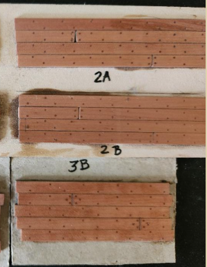
Photos of some test samples are below. Plank and treenail tests have different combinations of treatments. Planks include sanding sealer, Tung Oil, Bitumen wash with white spirits, and Bitumen/bees wax. Treenails are all of the same pearwood as the planks, but have three different treatments, including 1) no treatment, 2) flat black paint, and 3) graphite treated low viscosity PA glue applied during installation.

View attachment 513691

Although the samples are all relatively close in appearance, there are some subtle differences. I've yet to decide which I prefer. Input is always welcome.

So we all know the importance of using GREEN mats. I think I've uncovered some false advertisement in marketing. Mine are supposed to be "self-healing". I'm waiting for the drill holes to heal themselves! ROTF :rolleyes:
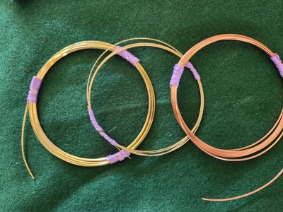
View attachment 513704View attachment 513705For the Wales bolts, I wanted to use copper or something similar. The photo below shows half-hard square copper wire as well as half-hard square red brass wire. From the usual viewing distance, you really can't tell the difference. Under magnification, the differences are slight. The key difference is that, even though both are "half-hard," the red brass was noticeably harder and therefore easier to work with during installation. So the decision has been made.

Thanks for stopping by to visit.
I like those 'B' results *below). The treenails are subtle and thin caulking.

1744685888919.png
 
Jim, Peter, and Grant, thank you for the input. I was leaning this way, as well, but was not sure if they were too subtle. Fortunately, they are the easiest to apply. Thanks agains.
First, I'd probably pick the easiest. Most people wouldn't notice the difference, maybe not even Paul. Second, I prefer the more subtle look on treenails. When I look at real ships, they're hardly noticeable.
 
Someone asked me a question in DM. I will answer here, with the hopes of perhaps helping others that may have the same question.

"Quick question for you - I read your post and will be using some for the bolts on the frames on my La Renomme build soon. I noticed you prefer the half hard variety which makes sense. I could not tell in the photo but I am leaning towards Red Brass vs Yellow Brass as I will not be blackening and hope that it will dull down over time."

All three, Yellow Brass, Red Brass and Copper will tarnish naturally over time. At what speed, relative to each other? I don't know. But the key is to make sure the wire that is being used, especially if it's being purchased from a jewelry outlet, is that the wire is "uncoated", or unprotected. Many jewelry outlets sell coated wire, understandably so the jewelry being made does NOT tarnish. Make sure it's uncoated or it will not tarnish, blacken or accept any other treatment applied.

Personally, I wanted to use copper for the same reason as you. But due to the construction of the ship, all my treenails and bolts will be functional, fastening the planks and wales to the ships hull for added and permanent adhesion. Copper proved to be too soft to seat all the way to the shell of the hull.

Bottom line, there is a slight difference in appearance, but at 22 gauge I'm not sure anyone will notice. I will be going for a slight weathed look and will treat, "mist", the bolts with a solution that will take the shine away and add a slight worn look.

Below, left to right: Yellow Brass, Red Brass, Copper. It is my understanding Red Brass is Yellow Brass, with a slightly higher Copper content.

All three will tarnish, but again for me the choice was weighted to either brass wire, due to my functional requirement. Had I been able to use the Copper wire, I definitely would do so, as I think you will be able to see a bit of difference when viewing the bolt application across the entire wale. I will be using Copper for the inside fasteners of all gun port lids.

Hope this helps!

thumbnail.jpg
 
Thank you all for the warm welcome back, taking the time to visit, and all the likes.

A small update. I started planking the hull, between first and second gun decks, only to realize I'm human and to be one is to err. :rolleyes: After planking the bottom three of four runs of planks, I realized that the gun port cutouts on the bottom plank were incorrect, as they accounted for the sills of the ports extending to the outer edge of the external planks. I decided not to follow this standard for cosmetic reasons. The result was that the cutout was vertically too large. So off it came, and I'm now in the process of reconfiguring.

So as we do, when we get stuck, we take a small step of testing the plank fasteners' appearance, treenails, and bolts. French 74s of the period typically had a combination of treenails and iron bolts, offset and alternated, below the waterline. I will not be following this standard, installing treenails only below the waterline.
,
Photos of some test samples are below. Plank and treenail tests have different combinations of treatments. Planks include sanding sealer, Tung Oil, Bitumen wash with white spirits, and Bitumen/bees wax. Treenails are all of the same pearwood as the planks, but have three different treatments, including 1) no treatment, 2) flat black paint, and 3) graphite treated low viscosity PA glue applied during installation.

View attachment 513691

Although the samples are all relatively close in appearance, there are some subtle differences. I've yet to decide which I prefer. Input is always welcome.

So we all know the importance of using GREEN mats. I think I've uncovered some false advertisement in marketing. Mine are supposed to be "self-healing". I'm waiting for the drill holes to heal themselves! ROTF :rolleyes:
View attachment 513704View attachment 513705For the Wales bolts, I wanted to use copper or something similar. The photo below shows half-hard square copper wire as well as half-hard square red brass wire. From the usual viewing distance, you really can't tell the difference. Under magnification, the differences are slight. The key difference is that, even though both are "half-hard," the red brass was noticeably harder and therefore easier to work with during installation. So the decision has been made.

Thanks for stopping by to visit.
I also make samples, and soon I expect a new delivery of pears. And I again expect samples. I would like to see your results at a closer distance, so that the image quality does not distort the result. But thank you for sharing the result.
 
Thanks Ken - I saw your link to where you purchased the wire - I assume the wire you purchased was uncoated. If so Ill go ahead and purchase from the same source.
 
Thanks Ken - I saw your link to where you purchased the wire - I assume the wire you purchased was uncoated. If so Ill go ahead and purchase from the same source.
NP Chris, Just to be clear, the site I linked, being a jewelry supply site sells both coated and uncoated wire. The coated wire will state it's coated on the label, the uncoated makes no mention at all. So read the product details to ensure you don't get an unwanted surprise later. ;) After posting, I did go back and cut off a small piece of all 3 of the wire samples and blackened them successfully, just for my own peace of mind.
 
Hello Everyone, as planking continues above the waterline, the port side is just about finished. I'm holding off on photos until it is completed.

With that said, and to help break up the monotony, I decided to address another issue/challenge of scratch building. What to do about sourcing small metal worked parts? While I'd like to make EVERY part on the ship, I have to take into account my skill set and time investment. At 68, time is the most precious of commodities. ROTF I'm ok with sourcing items from supply sites, if I can't make the item myself, or making the piece would be time-prohibitive.

So I decided on a small feasibility project, photo etching small metal-worked parts. This post is a bit long as I wanted for it to have some tutorial value, if someone decided they'd like to go down this road. With that said, onward.
Some of the key considerations in my ultimate decision are;
  • Quality
  • Scale
  • Cost
  • Fabrication time
  • Uniformity
The test required a small investment of money and time, but if I can pull it off, it will pay itself off quickly and can be used for all future projects.

I've done quite a bit of research and the process, at first glance is "involved", but like any other multi-step process, it's about flattening the learning curve and understanding the tolerances of each step. Some steps are dependent on the step decided or executed prior.

Process Steps
  1. Requirements: metal choice, thickness, size, etc. (these will affect the exposure time, etching solution used, and/or etching time.
  2. Artwork: needs to be carefully prepared in scale and registration.
  3. Metal preparation (nothing special- same prep as for blackening).
  4. Photoresist method (in this case, negative-explained later), in this case, the use of dry film. Liquid paint can be used, like Positiv 20, is more convenient, but it is not available in the US.
  5. Adhering photoresist film to the metal.
  6. Exposure method (in my case, built UV light box) testing times
  7. Post-exposure wash (to remove exposed film)
  8. Etching
Requirements
I will almost always use Brass, although Copper is an option. Thicknesses will range from 0.2 mm to 0.9 mm. Each will have its own requirements. The etching times for thin pieces will be much less than those for thicker pieces. Times may be adjusted by increasing the etching solution's concentration.

Artwork
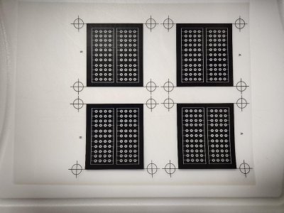
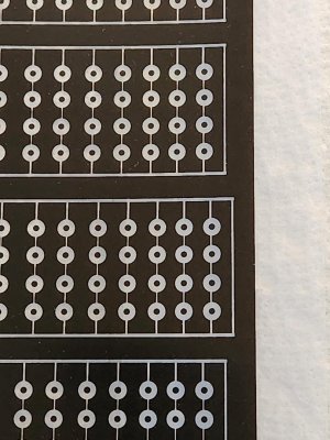
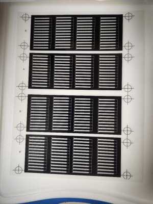
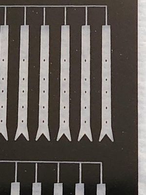
IMPORTANT: Only Vector graphics can be used in the artwork. It is the only way to produce crisp borders. The pieces I need and decided to use in this test are gun port hinges, as reasonably scaled hinges could not be found online. And secondly, washers for the hooked bolts used for attaching gun breach lines and gun tackles.

I used Adobe Illustrator on a 7-day trial, which has now expired. The Washers are drawn, starting with ONE washer, cloned, grouped, and cloned again, until I end up with an appropriately sized template for testing. Even being careful, there are some variations. Since etching will be performed on both sides of the brass sheet simultaneously, you need two identical images. So I took one of the images, cloned it, and then flipped it horizontally, added registration marks to ensure they are aligned exactly. This is absolutely the most important part of ensuring a good result and is not to be rushed. If they are not, the etching quality suffers, and there is no range of quality here. It is either acceptable or not. Brass thickness for the washers is 0.2mm.

A couple of additional notes. The artwork is printed on "waterproof transparency film", which is used for inkjet printers. Only one side is printable. Very clean borders were achieved this way.
thumbnail (26).jpg
thumbnail (7).jpg

For the gun port hinges, I used 0.4mm brass sheets.

thumbnail (20).jpg

Note: The connectors that tie the pieces together need to be at least 0.2mm. If you look closely, the image below is very slightly extended/stretched vertically, resulting in the bolt holes being slightly oblong in the same direction. More on that later.

thumbnail (9).jpg

Ok, so I now have artwork.

Metal Preparation
Same as preparation for blackening.
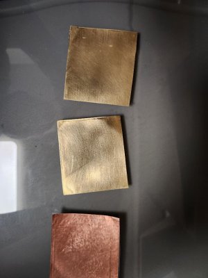
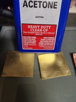
Sanding, 320grit, 400grit. I test by dripping water on the metal. If it spreads naturally across the surface of the brass and does not bead up, it's good to go.

Then cleaned with Acetone and put aside to dry.
thumbnail (24).jpgthumbnail (25).jpg

Photoresist Method and Preparation
I used Dry Negative Photoresist Film.

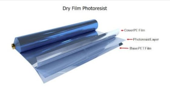
This film has three layers: the middle layer, which is the actual photosensitive layer, and two outer protective layers.
bandicam 2025-05-05 11-39-23-278.jpg
The trickiest part of this entire test was peeling away one of the protective layers. All my research said this must be done in a dimly lit environment as not to overexpose the film, done with gloves, and for me, with arthritic fingers. I learned that as long as it's not in direct sunlight, it would take 30 minutes for the film I used to become affected.

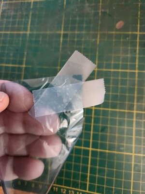
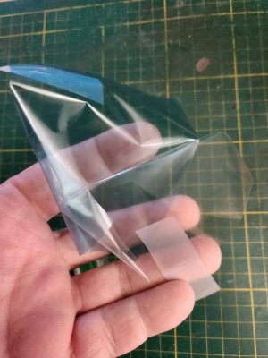
A method that helped separate the layers was to place a piece of tape in one corner of the film, offset from each other, and gently pull apart.

thumbnail (32).jpgthumbnail (33).jpg

Then the photo resist film (blue tint) is placed onto the brass sheet with a little water on it and work middle out to smoothly adhere the film. I used a credit card as a squeegee. Repeat on the other side of the brass as both sides will be etched simultaneously.

The last step in this Part 1 is adhering the photosensitive film to the brass stock. The next series of photos was taken just now, as I realized I forgot to take photos of this step. In the first photo, you can see little air pockets, which I would have squeegeed out if it were a real production step. With that said, it provided a great learning opportunity to see what would happen if they weren't taken out.

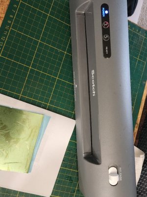
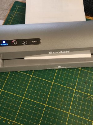
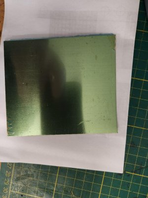
The brass sheet is then put between a folded piece of regular printer paper and then run through a laminator. You don't need to use real "carrier folders", normally used to protect the film from the heat of the laminator. Also, I've seen other tutorials that demonstrated the use of a clothes iron, which I imagine would work fine. One person used a heat gun, but I would not try this as it lacks the pressure needed to adhere the film to the metal.
thumbnail (36).jpgbthumbnail (35).jpgthumbnail (34).jpg

You can see even without taking the time to squeegee out any bubbles, the laminating process pretty much did the job, although I would not skip this step in a production run.

Ok, that's the end of Part 1.

To be continued...
 
Hi Ken,
This is really fun to do.
For the crisp finish of the parts you really need the photo etsch.
For course parts you can also use the laser printer. Just print the item you need on the laser printer. Clean the brass with acetone and use an Iron to Iron the image from the paper to the brass on both sides of the brass.
Simple but effective.

Looking forward to your 2nd part.
 
Photo Etching Part 2

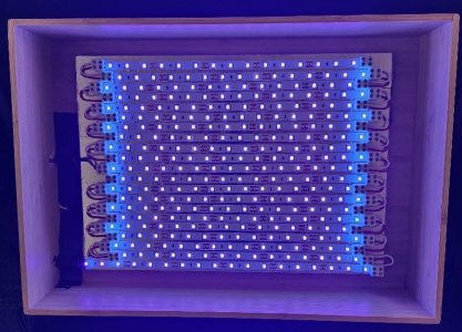
The next step, building the UV Light Box used to expose the film. It is a DIY effort. Now I know when it comes to building things, my skills don't come close to the mad scientist skills possessed by my friend Stephan, I just hope my efforts produce something that works.

Materials

Ignore the glass dishes and photo roll (black tube). Also, not shown is the UV LED strips' hardware (in the box) and electrical connecting wires that run the series.
  • Bamboo box, only 3.5 inches deep, but I can always increase the distance of the lights from the prints manually.
  • Aluminum tape
  • 1/8in x 8.5in x 11in plywood
  • UV LED strips, with remote control dimming and timing, which I thought would come in handy, and at $16, I could not pass up.
  • LED strip connectors (I chose these to eliminate any need to solder)
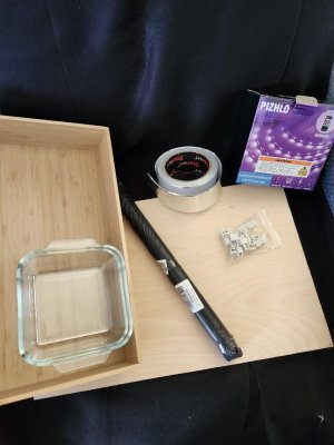
Materials).jpg

First things first. Use the aluminum tape to cover the plywood, which provides some UV reflective value.
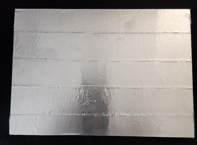
thumbnail (6).jpg
I then mapped out the LED strips and staggered each row to provide a little room when making connections. Since there were two power connectors were provided I decided to use each one to power only 1/2 the bank of LEDs, ensuring sufficient power to all LEDs.
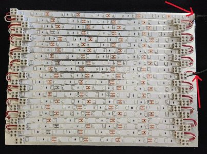
thumbnail (5).jpg

Testing, 1, 2, 3. Oh, wait, I mean POWER UP! It's important to understand not to look directly into real UV light, as it most certainly can damage eyesight.
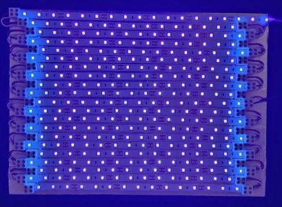
thumbnail (4).jpg.

In the box. The LED board is held in place using two large Velcro strips. I wanted the ability to remove if I had to work on it in the future. I almost grabbed the Hot Glue Gun...RedfaceROTF
thumbnail (11).jpg
Outside box, with power and controls.
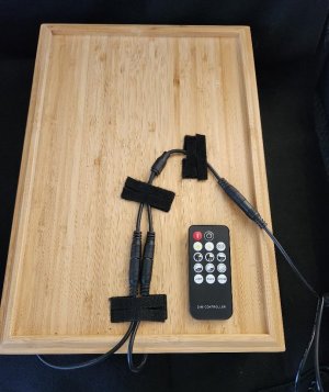
thumbnail (2).jpg

Ok, now that the light box is ready, it's time to prep the test samples, bolt washers first. I take the two identical test pieces of artwork, tape the first one, printed side UP, to the desktop. Then its partner and place it on top of the first one, printed side DOWN. Then, using three small pieces of tape, tape the two pieces on three sides, only after I've ensured the registration marks are aligned. The fourth side remains open, forming a pocket. The brass test sheet is inserted into the pocket.

Note: The arrows below point out anomalies in the ink coverage on the artwork. This can happen during the printing process or, more likely in my case, when I inserted the brass sheet into the pocket, scraped the ink. In either case, these can be covered up with a black Sharpie, EZPZ.
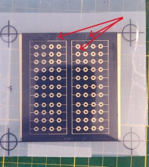
thumbnail (39).jpg

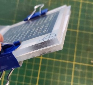
To ensure all three elements remain in place, I create a sandwich with two pieces of Plexiglass being the "bread".
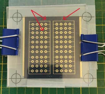
thumbnail (37).jpg

thumbnail (38).jpg

I've read so many tutorials online, each having its own set of variables when it comes to this step. There are really three variables that directly affect the exposure.
  • The power of the LEDs or light
  • The distance of the sample from the light source
  • The time of exposure
Being my first run, I had no point of reference. So I decided, based on everything I read, to create my own point of reference for the exposure step.
  • Full power of the UV LEDs
  • 5 inches of proximity from the sample
  • 6 minutes of exposure, each side
I did that for both samples and ended up pleased with the results of both. The exposed film seemed to take on a muted purple color after being cured, bolt washers below.
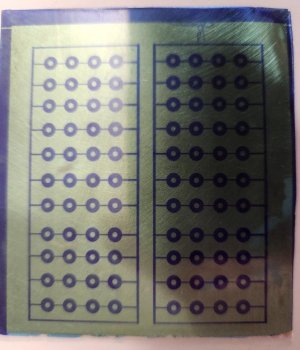
thumbnail (23).jpg

Tight, crisp lines. I'm :D.

Up next....

The Wash
Note: The final steps involve caustic chemical agents. I wear gloves, protective eyewear, and even an apron. While both of the agents I use, Sodium Hydroxide (Lye) and Ferric Chloride, are on the low end of the caustic spectrum, both will cause skin burns or serious eye damage. It's always slow and steady. I chose these two chemicals BECAUSE they are the milder choices. Other tutorials prefer other more caustic agents. The difference in the choices is straightforward. The more caustic the chemical agent, the faster the metal is etched, and the more harmful they are if mishandled. I can wait 1.5 hours for the final etching, compared to 15 minutes.


Ok, the "Wash" is the step that washes away the unexposed, uncured areas of the photo film. The first step is to remove the outside protective film that is still in place on BOTH sides of the brass sheet. BOTH sides, Einstein!!!! More on this later. :rolleyes:

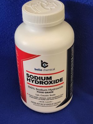
Once the film is removed, a wash bath is created by combining Sodium Hydroxide and Demineralized/Distilled H2O. While many people online state the ratio does not have to be exact, once again, working with chemicals, I always start conservatively on the "mild" side, always with the option of strengthening the solution if it isn't as effective as expected.
thumbnail (41).jpg
My wash ratio was 5 grams of Sodium Hydroxide to 150 ml of distilled H2O. This worked fine. So after thoroughly mixing, I submerged both samples into the wash and let them sit for a minute. Then, with an old, soft, small paintbrush, I gently stroked the bass sheets for about 30 seconds. Looking carefully, you can see the film slowly being washed away, leaving the purple cured film.

After doing for both samples, both sides, they are removed from the wash and put into a container of distilled clear water, which stops the wash process.

My results were mixed, but valuable.
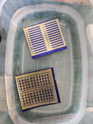
thumbnail (21).jpg

So, again, for the final etching step, every area where you can see brass, that metal will be etched away, the blue will remain and after a final wash, leave us with tiny identical parts, hopefully. At first glance, everything looks great, but....
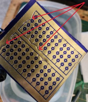
thumbnail (30).jpg
The sprue connectors that the arrows point out have delaminated from the metal. I'm ok with this. The reason I'm conducting this test is to identify and resolve any issues before the real production runs.

So, I believe that there are a few reasons the cured film would delaminate from the brass.
  • The metal was not cleaned sufficiently, and dirt or debris prevented the film from adhering completely
  • The sprue connector was too thin to provide the same adhesion
  • The temperature of the lamination process was not hot enough to achieve the same
It could be all three. No worries here. It is not a deal breaker. Now, if 80% of the sprues did not adhere, I would have a big problem, but this one is manageable.
Next step...

Etching
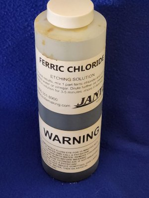
Etching is the removal of the unprotected metal, leaving you with the areas that are protected by the cured photo film. The etching agent I used is Ferric Chloride, 40% solution, which I used straight out of the bottle. This is not some crazy caustic, like Fluoroantimonic acid. Still, I'm very careful. Again, I chose this agent to preserve safety over expedience.
thumbnail (40).jpg

Below you can see the "bolt washer" test plate in the Ferric Chloride solution, diluted. I later realized I needed to use it at full strength and adjusted. (Sorry, no photo). Ok, so the final results for the "bolt washers" test were compromised by my wandering mind. I referred to this earlier in the post, with the "Einstein" comment. When preparing the brass test sheet for washing, I forgot to remove one side of the protective film. It was still in place during the final etching, affecting the removal of metal. Instead of the etching taking place on both sides at the same time, resulting in the removal of metal uniformly, one side was protected from the etching agent, resulting in over-etching in some areas and not in others.
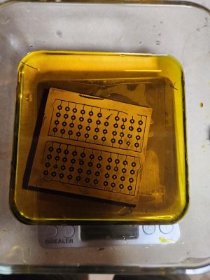
thumbnail (22).jpg

I had no predisposition for the outcome of this test. Success or failure, the truth lies in the feasibility. Can I use this process to create my own uniform, tiny, metal ship parts, or not?

Note: This is not the all-or-nothing solution. Keep in mind, I can still create the artwork and then send those Vector images to a 3rd party service that will create them for me. I can't remember who, Ondras or another master builder, does just this, measuring the value of time and effort. The only downside here is being at the mercy of the lead time of that company, which is not a big deal, as I can be working on many things while waiting.

Ok, after all the exposed metal is etched away, you are left with these parts, albeit covered in cured photo film, again, sorry, no photos.

So what is needed is a final wash, same as the first wash, just let them soak and brush away the film. It just takes about 7 minutes.

WARNING: The next photos are explicit and may be disturbing. Viewer discretion is advised!

Gun port hinges.

Pros

  • All parts were fabricated, that's it.
Cons
  • Uneven etching
  • Side etching, resulting in rough edges, that will need to be worked (sanded, filed) to make smooth.
With these observations, it's important to note, the photo is magnified and the end result, with a little work, is acceptable, in my view on the ship with human eyesight.
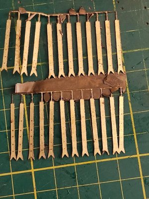
thumbnail (27).jpg

Bolt Washers

Pros

  • Not many. Some washers turned out well, others not so much. Concern is the lack of uniformity of final product
Cons
  • Many, however, I cannot attest to the efficacy of this test as I screwed a few things up
Leaving the protective film was a biggie. Additionally, the sheet thickness being 0.2mm left me with little or no room for error.
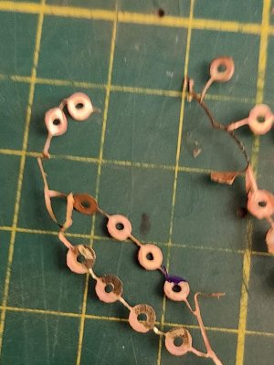
thumbnail (28).jpg


So what now?

Observations
The process of photo etching metal, brass, or copper is feasible. I'm not at all discouraged by the results I achieved, knowing nothing. I honestly feel the shortcomings of the final product can be rectified with a little practice and honing down the variables.

The process, when first read or even first practiced, seems very involved, but actually, it is not. There are dependencies that need to be followed, but overall, it is very logical.

This exercise was eye-opening for me. I think my final decision as to whether I will photo etch my own parts or not will depend on whether the quality meets my expectations, on the ship, in scale, and not a magnified photo. The other option is outsourcing the actual process after creating the artwork. The last option seems very viable at the moment.

Before I make a decision, I will take it to the next step, once I'm bored of planking again. I will adjust the variables that I believe caused some issues and see if the final product is of a higher quality.

Secondly, I will take these parts I made and work a little bit with a file and sandpaper and see how they present in their application on the ship (test hull).

Thanks for looking in. Don't be discouraged, I'm not

Cheers
 
Last edited:
Hi Ken,
This is really fun to do.
For the crisp finish of the parts you really need the photo etsch.
For course parts you can also use the laser printer. Just print the item you need on the laser printer. Clean the brass with acetone and use an Iron to Iron the image from the paper to the brass on both sides of the brass.
Simple but effective.

Looking forward to your 2nd part.
Hey Maarten, Yes, I just needed to find out for myself. With time, cost, and quality of parts all having an impact on our hobby, I felt the need to explore and understand more. Thanks for stopping by.
 
Back
Top