LE ROCHEFORT

Don,
If you have the English version of the text from the monograph, please check the composition of the frames in the section dedicated to the explanation of each individual plate.
Plates 3 and 4 show all the frame patterns.
The explanation of these 2 plates should be grouped as 1 entry in the book. These explanations should cover a few things, including the orientation of the frames.
Another paragraph in the text on the page should cover the composition of the frames: describing the different parts of the frame by name, ie: floor-timbers, half floor-timers, futtocks, etc...
In regards to the most forward and aft frames, their composition is usually slightly different: for example the floor timber is called a half-crotch (2 of them) and the half floor-timbers are replaced by cross-chokes (1, 2 or 3 depending on how severe the V shape to the foot is: See HERE for a diagram and associated text (not Rochefort though): once you have clicked on the link, scroll down to page 77 and look at photo 5 showing an exploded view of the lower part or foot of the frames..

I suspect that the most forward and aft frame of Le Rochefort are built in a similar way. The information is contained on the plan.
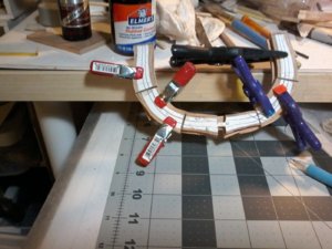
Looking at the your last photo (frame 2), it seems that the foot of this frame is composed of 1 cross-choke (its location being on the bow side) and 2 half crotches (on the stern side of the frame).

Let us know what you find in the text and if the description makes sense.

G.
 
will do GILLES and yes i have the ENGLISH instructions will reviw it again, and BTW they and the whole MONOGRAPH IS EXCELLENT would recomend as a first time scratch build. AS ALWAYS Don PS do you recomend my making the one put together to be re-done making it thicker I think so as this frame is the key for the HAWSE timbers to sit on
 
ALSO the monograph/practorium of the GROSS VENTURE is a must for any builder building A POF BUILD FOR A FRENCH SHIP, everyone should afford them selves of this gift from GILLES. Thanks again my friend Don
 
do you recomend my making the one put together to be re-done making it thicker I think so as this frame is the key for the HAWSE timbers to sit on

Don,
If you are talking about Frame 1.
It is up to you to redo or not.
If you are ok with the way it is at this point, don't redo. If once you have built your hawse-timbers you think it need to be redone, then ....

If you are talking about redoing the forward and aft frames according to what you find out from the text:
I am thinking that you have already done all the forward frame, so it is up to you decide if they need redoing according to what the description is in the text or not: every modeler sets his / her own standards. I do not see much wrong in that. And frankly, once the framing is complete, you will be the only one knowing......

If you have not done the aft frames yet, then you should make them with the proper composition. If anything it will give you the experience for your own learning experience and benefit.

G
 
Hi GILLES I am re-doing a lot of the frames to keep them in line of the rest I have 7 more to do, my material will be in this week, so i will continue with the frames, and yes i will be starting the aft frames next and completing frames No.1through5. THANKS AGAIN Don
 
hi all while waiting for materials to arrieve this week, i am straighting ot my work space, and thinking about how to proceed on some other items, showing pictures of the hawse details and how i am thinking of procedding wit this, you can see the template/jig i hope to use also the filler pieces shown on the plans with dimensions, this idea came from GERARDS FORUM build by JMAU it is on page 2 of his build scroll down a little you can see how he does it, so please comment on this and any other ideas greatly appreciated20200205_210800.jpg20200205_211029.jpg
 
hi all while waiting for materials to arrieve this week, i am straighting ot my work space, and thinking about how to proceed on some other items, showing pictures of the hawse details and how i am thinking of procedding wit this, you can see the template/jig i hope to use also the filler pieces shown on the plans with dimensions, this idea came from GERARDS FORUM build by JMAU it is on page 2 of his build scroll down a little you can see how he does it, so please comment on this and any other ideas greatly appreciated

Don,
It looks like a good start of the Hawse timbers.
In general, the technique used is proven and as long as you get the angles right, these tricky parts should turn out well. As always, leave meat on them until you know the angled-cuts are good so that you get the right shape and spacing.
Regards.
G.
 
Hi Janet, this is not my first POF it is my 4th POF it is my first SCRATCH BUILD, the rest of my POF were all what i call SEMI-KITS, yes i could have chosen another simpler one but this one suites my purpose and with GILLES AND OTHERS HELP will put me on the path of other scratch builds. Don
 
Hi donfarr, thank you for email, no criticism intended I think you are very brave to take on what to me seemed a difficult build. However I to have the
drawings and I would like to take on this ship, I wish you a enjoyable build keep up the good work.
Regards JANET
 
Hi Janet, NONE TAKEN, it gets easier as you go along, my begining problems not only FIRST SCRATCH BUILD and first FRENCH ship, and also the monograph PDF printed out it was dificult at first inturpting the monograph and going back and forth also the plans for me needed some time to understand, but as I said it gets easier as you go along IF YOU WANT To build this ship I sugest you review my log when GILLES STARTED TO MENTOR ME invaluble help also to down load his monoraph/pratorium on the GROSS VENTURE even though the ship is different it is invaluble for anyone doing a FRENCH SCRATCH BUILD many, many simularities the link is on my log I think it was page 13 not sure but do that A great help, and also welcome back to the build i finshed a HAN BUILD OF THE HALIFAX (THE LUMBERYARD) it turned out OK but not great, had a really big problem with the STERN had to fudge it a little, log is on this site, and BTW I am going to be 82 in april a lot of physical problems but still grateful for WHAT JESUES HAS GIVEN ME. Don
 
OOPS FORGOT JANET my bigest concern was a building JIG and it still is, i have tried to cut my own but can not do AGE PROBLEMS( COORDINATION NOT WHAT IT ONCE WAS also eyesite etc) so i am going to use the building slip/ jig that I bought a couple of years ago, my first try with it, it is very heavy and you need a lot of room, when i bought it it was a resonable price it has gone up quite a bit (POLISH Co.) and the make a smaller one have to check it out, hope this is helpful. Don
 
hi everyone a question as i move on more frames done (re-dos) having a problem to see what 9i am doing wrong, pictures show what i am having a problem with, when i do the joints on the sander they come out excellent tight good fit for the next fuutock but when i match the lines up they do not corrospond the picture i show is after re-doing one futtock i hope i am explaing the problem correctly, i must be doing something wrong here, ALL HELP SUGESTIONS etc ARE MORE THEN WELCOME20200209_235107.jpg20200209_235319.jpg
 
hi everyone a question as i move on more frames done (re-dos) having a problem to see what 9i am doing wrong, pictures show what i am having a problem with, when i do the joints on the sander they come out excellent tight good fit for the next fuutock but when i match the lines up they do not corrospond the picture i show is after re-doing one futtock i hope i am explaing the problem correctly, i must be doing something wrong here, ALL HELP SUGESTIONS etc ARE MORE THEN WELCOME

Hi Don,
Please clarify your question:

a) Is your frame part too short after sanding the joint edge? Leaving a gap between parts when they are laid over the frame pattern?

b) Is the butt-joint angled or too short or too long? So that once the 2 parts are joined, you lose the alignment over the pattern?

If the joint is sanded at an angle from one of your part's original pattern, the other end of one of the parts to be assembled will end up out of alignment.
If it the joint line has been sanded too much or not enough, you will end up with the next part being out of alignment as well as it will be too short or too long compare to the original frame pattern (as a whole), this being out of alignment: offsetting the curves out of alignment.

One needs to be careful in sanding the joint lines. They must be straight, they must be sanded in the appropriate angle and following as closely as possible what is drawn on each part of the frame. The best way to do this is to sand half the line if possible: so that you end up with half the joint line on each of the 2 parts to be assembled.
Of course, it can be an issue, but small single inaccuracies are not so much of a problem, as the can be compensated for, but keep in mind that when they accumulate on one same frame, you may end up with a larger problem.
Model ship building is a lot about avoiding accumulating small errors that affects the next step in a larger way.

In short, that is why, you leave meat around the contour of the frame so that minor errors (contour line slightly out of alignment) can be taken care of when sanding the framing as a whole: once the hull has been assembled.

regards.
G
 
Hi Gilles, It is (b), sometimes OK but sometimes not and yes it can be fixed by re-doing the futtock in question, i will take more pictures and post them latter, AGAIN I WILL NFOLLOW YOUR SUGESTIONS,THANKS AGAIN Don
 
Don,
Just to show you that the most important part of frame construction is the accuracy of the joint between frame parts......

1) After sanding, the joint line is straight on one part and angled on the second part to be assembled.
The pattern lines are out of alignment and here is the result .... the opposite end is off...... and it does not take much of an angle difference to be off.......

align 1.jpg

2) The joint lines are straight ........
The pattern lines look ok and line up

align 3.jpg

3) And here is the result:

align 2.jpg


G
 
YES GILLES, and i am getting there, question how do you get both the angle and the joint lines to be correct i am cutting and sanding to the pattern line sometimes it is both ok and some times one is ok and one is not i can correct it i have found out that sometimes i need to shift the futtocks to get both right, but do not understand why if i cut the patterns correctly they should work, what am i doing wrong some thing from the beginning, also something else i found out the angle of the joints also effects the height of the top futtock this can be critcal for getting the corect locations of decks, deck clamps etc. latter on so i must be careful of the top also, and maybe more meat left on, what i am seeing in this method is something that DAVE STEVENS has talked usin the blanks in the HAHN TYPE construction witch i can not do, but i truly seeth value of leaving plenty of meat on the frames and other parts, THANKS AGAIN YOUR HELP IS FANTASTIC NOT JUST FOR ME BUT FOR SOS MEMBERS AT LARGE ESPECIALL THOSE WHO DECIDE TO DO A FIRST TIME SCRATCH BUILD. Don
 
question how do you get both the angle and the joint lines to be correct i am cutting and sanding to the pattern line sometimes it is both ok and some times one is ok and one is not i can correct it i have found out that sometimes i need to shift the futtocks to get both right, but do not understand why if i cut the patterns correctly they should work, what am i doing wrong some thing from the beginning, also something else i found out the angle of the joints also effects the height of the top futtock this can be critcal for getting the corect locations of decks, deck clamps etc. latter on so i must be careful of the top also, and maybe more meat left on, what i am seeing in this method is something that DAVE STEVENS has talked usin the blanks in the HAHN TYPE construction witch i can not do, but i truly seeth value of leaving plenty of meat on the frames and other parts,

Frame construction: alignment issues....
Here is what could go wrong at the beginning of the process during the transfer of the individual parts composing the frames:
- The entire frame pattern is photocopied: this is straight forward.
- Individual parts of the frame (floortimber, futtocks, etc...) are cut out (away from the lines): this is straight forward.
- Individual parts of the frame are transferred to the lumber (in most cases glued on the wood).
This is one area where things can go wrong as the patterns may get very slightly deformed, stretched or bent out of shape, especially if the paper is just plain copy paper. I would think that heavier weight paper (bristol paper) may work better as it is stiffer to reduce chances of that happening.
But, this is only my "logic" speaking.
In any case, the method is widely used and proven ...... so it does work. This said it is like everything else: care must be taken during this step: transferring the paper pattern to the wood.

As I explained much earlier, personally, I prefer to transfer the pattern via the use of tracing paper. It pretty well has the same inconvenient, possible deformation of the individual part pattern, but this is what I am used to: plus I do have my "checks and balances" to make sure that it is as accurate as I can get it . Furthermore, I work slowly and carefully as my eyesight is not what it used to be.
The odd futtock does end up being slightly off. In these cases, I adjust the angle as it does not take much to correct: adjusting the angle of the joint line = slight inside or outside rotation to bring the part in line. If I go too far, then the part is redone (although rarely). If the frame ends up being a millimeter short, it does not really matter. If the alignment of a part of a frame is very slightly off, it does not really matter either. In either cases, corrections can be made when assembling the part butted to the part slightly out of alignment.
The bottom line is that I am not bad at cutting right on the line, straight or curved, with my hand saw............. but "what for".

Also, once you have done your best to transfer the parts on the wood, however you do it, to make sure you are sanding straight to the line and at the right angle use good lighting aimed at the disk sander, and if you have issues with eyesight, mount a magnifying large glass over the sanding table. You can also use magnifying eyeglasses, 2 to 3x power reading glasses (that's what I do)...... but I am sure you already adapted your work space to your conditions.
Kindest regards.
G.
 
Last edited:
Hi Guys, back showing the rough shape of the DOUBLE FRAME No.12 had to do some shifting to get the JOINTS RIGHT and as GILLES said the angle correct for nthe adjcent futtock, als showing the rough very rough completed frame my next step is to grind the frame to an acceptable curve so far have had a lot of sucess by ding this so i will show the after picture tomorrow after glue dries, and another big shout out to GILLES, and please all comments and sugestions are greatly valued20200211_000314.jpg20200210_233316.jpg20200210_231542.jpg20200211_005639.jpg20200211_005744.jpg
 

Attachments

  • 20200211_000111.jpg
    20200211_000111.jpg
    190.8 KB · Views: 3
Back
Top