Hi Don,
Your problem must be due to only having the keel notch as a reference for lining up your 2nd layer.
If I understand correctly your build your frame this way:
1) Transfer of the frame parts (patterns) to wood (paper cutouts glued to the wood).
2) Cut individual wood parts.
3) Work on joint lines with disk sander.
4) Built layer 1 (frame's bottom layer) over the frame plan: aligning everything according to the full frame pattern: paper patterns facing up. Starting with the floor-timber and working your way up to the top-timbers.
5) Flip layer 1 so that the paper patterns end up face down.
5) Build layer 2 over layer 1 (layer 1 is now showing no lines) only aligning the 1/2 floor timber notch to layer 1. The rest of the 2nd layer parts being butted together without alignment reference.
6) once the frame is assembled you have the paper patterns showing on layer 2, flipping the frame over you also have paper patterns showing on layer 1 as well.
If so, because the frames are built leaving a lot of meat, you have little or no reference to built layer 2 on top of layer 1.
The bottom line is that you need the original line contour and the joint lines of the frame and as a reference to built each frame correctly.
So maybe you need to extend a few lines on your overall paper frame pattern so that, at least, you have some points of reference in every step of frame assembly.
You could extend the top of the frame lines as well as the joint lines. (similar to what you see in the first image below)
PLEASE READ THE FOLLOWING NOTES VERY CAREFULLY understanding that this is only a suggestion to help you digest the frame building process. By no mean, this is the best process but I think that it will help you.
Here is an alternative frame building process to keep your basic needs for alignment, working from one layer to the next.
I can tell you that everything described below can be done while sitting down. The only thing is that you need to be able to look at your work from above: so you need an adjustable office chair if you have one, or a table that is a bit lower than normal. You can of course adapt everything to your particular needs.
USE SCRAP WOOD and PRACTICE on one frame. Follow and alter the technique if need bet........ but concentrate on one frame until you get it right.
This is important (probably the most important words you will read in this post):
The best frame to practice on is you master frame (frame marked as
15-Mav ) as it is one of the few that are not as confusing with bevels, etc.... This frames only shows basic contour lines.
Work on this frame until you get it right. Work slow, and only get exited about working on this frame: only look forward to getting this one right for now...
Note: this is not a frame from ROCHEFORT but the basic process will be the same.
Step 1)
Extend your original line pattern like this: top timber straight up, joint lines extended past what you anticipate your wood parts to be: taking into account the extra meat you leave on the wood parts.
Keep this copy of the overall frame pattern to the side until your frame is assembled.
 Step 2)
Transfer the frame pattern to a sheet of tracing paper: again, especially making sure that the joint lines are extended well past the size of the individual wood parts once you'll have cut them.
This is the basis for your frame construction. Make sure this is as accurate as possible.
Notes on tracing from original pattern to tracing paper:
a) Tape tracing paper sheet to the original pattern. Trace all lines relevant to the specific frame you are working on
b) Trace the lines using a pencil with lead on the hard side: I use 2H
Again make sure the joint line are long and as accurate as you can make them.
c) Once you have traced the original lines, flip the tracing paper sheet up-side down and go over the lines again with a softer lead pencil: I use a 2B
at this stage, you really only need the contour lines: you do not really need the bevel lines.
 Step 3)
Cutout of the paper pattern needed for the top layer of the frame (end layer) only.
Please note that the pattern extends past the joint lines at this point.
 Step 4)
a) Glue the paper pattern to the wood: again paper patterns will be your 2nd layer.
b) Transfer the individual parts of layer 1 from tracing paper to wood.
The end result should look like this: parts for layer 1 (bottom layer) pencil lines, layer 2 (top layer) paper patterns.
Again, please note that when you cut around the patterns, you are not cutting to the joint line. Your final joint line is worked at the sander.
 Step 5
Cut individual parts, including the notches of the floor and half floor-timbers since they are different from one layer to the next. But that may not even be needed as they can be cut later once your frame is assembled.
Work on joint lines accuracy with the disk sander: spending time dry fitting each part to make sure all lines up according to the overall frame pattern. Start with the floor-timber and work your way up as if your were assembling the frame: piece by piece. You can fit each part individually on the frame plan as well as to checking the fit of the frame overall: as you progress and add parts butted to each other all the way up the frame.
Step 6
Once all you joint lines have been checked, assemble the 1st layer over your tracing paper sheet (you should tape down the tracing paper so that it does not move on you): aligning the parts with the pattern. You need to work on a flat stable surface (glass work well). That bottom surface is the same for the whole process. If you glue the parts to the tracing paper, which itself is taped to your work surface (glass), you can actually build the whole frame without having to move anything while you work. Do not lift the first layer once assembled. If you need to move what you have assembled, just move you work surface (again, glass works well).
The assembly of the first layer is where I personally use 2 types of glue as explained in one of my previous posts: craft glue for the bottom face of each part to secure the part to the tracing paper, wood glue for the joints between parts.
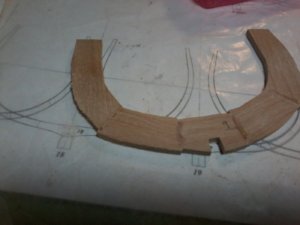
The image below shows individual parts assembled on half the frame (this particular frame is made of 2 separate halves), but keep going until the entire first layer is done.
 Step 7
Once the 1st layer is assembled, move on to the 2nd layer right away: again, not moving anything from the work surface. This time only wood glue is used.
As your 1st layer has the contour lines showing, all you have to do is to use them as reference for your second layer. You actually have 2 references: a) the contour lines from layer 1 and b) the extended joint lines from the pattern (tracing paper).
Once the pieces of your second layer are glued to your first layer, do not lift it from the work surface, do not use clamps to hold anything in place, just adjust you pins to fit the second layer as you go if you want: you may even realize that the pins are not needed anymore.


Once arrived at the stage shown in the image above, place a flat surface (glass works very well) over top of the assembly, some weight on top, and let it all dry.
The images show lines with a slight offset by in reality the lines match: top layer is aligned with the lines from the first layer and the joint lines on the pattern. The offset is due to the angle of view when the photo is taken.
The frame shown here is made of 2 half-frames, which you do not have on your ship but the basic process is the same.
Step 8
Set assembly aside for the glue to cure.
Step 9
Once the glue is dry, rip the tracing paper off the bottom face of layer 1: all the lines should still be there for later use.
At this point you can verify the fit of the frame over the original frame pattern (image shown is step 1). Then you can square off the contour of the frame
Again,
To end up with a frame that will fit into line pattern, you need to keep as many reference points as possible during the process. The joints need to be tight and accurate.
On a side note.
Gluing the individual parts of the 1st layer to the tracing paper pattern has 2 purposes:
a) it holds the frame in place while parts are being assemble together.
b) once the frame has been assemble and the tracing paper ripped out, all the lines show on the back face of the frame, which is helpful if one wants to shape the bevels.
Hope this helps.
And once again, This is only a suggestion.....
To ALL, Sorry for the long post.
Regards.
G.


")