LE ROCHEFORT

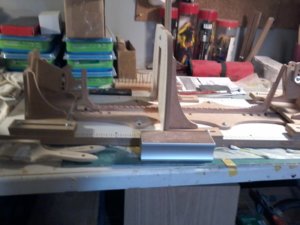
THANKS ALL GUYS APPRECIATE IT ALWAYS, AND I AGREE WITH DAVE STEVENS ABOUT THE JIG I DESPERATLY NEED THE JIG PREFERATLY LIKE THE ONE USED IN THE CAUSTIC, AGAIN DUE TO AGE PROBLEM I CAN NOT CUT THE JIG ACURATLY ENOUGH TO MAKE IT WORK, I HAVE SEARCED AND ASKED ON THE FORUM AND LOCALLY WHERE I LIVE FOR SOME ONE TO LASSER CUT THE JIG WILLING TO PAY RESONABLE EVEN FOR A GANTRY TYPE JIG BUT NO RESPONCES SO I HAVE ADAPTED TO THIS A COMBO OF DAVES IDEAS AS THE USE OF FILLERS AND TEMPORARY BATTENS PLACED IN THE VEY LARGE BUILDING SLIP FROM HOBBY ZONE HAD IT FOR QUITE A WHILE, I WILL POST ANOTHER PICTURE AND AS I HAVE COMPLETED THE KEEL INNER KEEL AND KEELSON WILL SHOW THOSE ALSO, NOW LIKE THE PILLS I TAKE ALL COME WITH SIDE EFFECTS THE PROBLEM HERE IS I TAKES A LOT OF ROOM TO USE THIS BUILDING SLIP AN A METHOD OF TURNING IT SOLUTION TO SET UP A SPACE IN MY SON-IN-LAWS GARAGE OR HIS OFFICE EXTENSIO OR HOME GARAGE IN THE COMING SPRING< ALSO THOUGHT ABOUT IN for looks purpases to incorporate filler pieces in to design of the hull using a different specises of wood as the plans do indicate the use of fillers, as i do not plan on planking the hull only a couple of planks above and below the WALES, and I do need opions for the use of fillers in a different species of wood, as to NIGELS IDEA I ALREAD USE A WHITE BOARD PHOAM BOARD THE THE INS WILL TRY THE MAGNETS, AND FINALLY THANKS AGAIN TO GILLES FOR COMING BACK PLEASE SIR STAY AND NOT ONLY HELP ME BUT THE WHOLE SOS FORUM. THANKS AGAIN Don


in order to draw a jig you would need the plans to get the measurements from so that is a problem with anyone drawing and cutting a jig.

the jig you show looks like a nice setup I think it will work out. You still need to add spacers to tie all the frames together.
 
HI GUYS , THERE IS A WAY TO DO THAT GILLES JUST NEED TO FIGURE OUT HOW, ONE WAY I MIGHT DO IS GET LONGER SCREWS ALSO VINCEP IN HIS LOG IS USING THIS SLIP/JIG I WILL ASK HIM, and DAVE OR GILLES WHAT DO YOU THINK ABOUT INCORPERATING THE SPACERS AS PART OF THE MODEL ITSELF USING MAKING SURE THEY ARE NEAT AND USEING A DIFFERENT WOOD, I PLAN TO USE 2 SPACERS ONE AT THE TOP AND ONE AROUND MIDSHIP, I am contiuing with the frames SO FAR SO GOOD i will not show each frame, but I still have some questions on the stern frames, and some others so i will post them, AGAIN THANKS GILLES AND DAVE INVALUBLE HELP. Don
 
Don, In regards to the jig, I guess you will eventually figure it out, depending as to what you want to incorporate in it and what you want the jig to be useful for.
I am certain you are aware as to what the jig is mainly used for….

As far as "spacers" (between the frames), I believe you already have some shown on the plan in the lower area of the hull, these are part of your hull framing.
For those, you can refer to the links I sent you a few weeks ago in private: Uwe also sent some in in post 282.

Depending on how you want to proceed with the assembly of your framing and the jig you will be using for it, You may want to add temporary spacers at the top of your frames if you are afraid for the rigidity / solidity of the hull, and safeguarding the alignment of the frames during subsequent operations (like sanding): in a way, connecting / tying (like Dave said above) all the frames at the top. Although... There are different ways to achieve that purpose. Some modelers, clamp temporary planks or rails either on the inside or / and outside.
You may not want anything permanent added to the actual framing, but then again, if you do you could place them in hidden areas.
Other members may give you other ideas.

What I have done in the past is similar to what others do. Temporary battens at the top and across the frame. In this case, the frames have been extending, but you could also do the same on frames that have not been extended. In any case, it would still be possible to remove the battens later on: when one feels they are not needed any longer.
This is not "Le Rochefort" but you get the idea.

top spacers.jpg

Once your framing has been completed, the keel, frames (including the small spacers on the plan) and the keelson have been assembled, these elements should be adequate for the rigidity of the hull: unless, of course, you plan on using a hammer and chisel to work towards the final shape of the hull.

So really, there should not be much to worry about in this regard. But this is only my view so other’s may differ.
If you want to add more spacers in hidden areas, it is totally up to you if it makes you feel more secure.

As for using a different wood for them, I guess, personally I would keep them the same as the frames ... but that would be a personal choice on your part.
G.
 
Last edited:
Hi GILLES, THANKS TO VINCE, (SOS MEMBER) HE STRAIGHTENED ME OUT HAD THE END PIECES UPSIDE DOWN, WILL SHOW CORRECTED IN TOMORROWS POST,, for members information I HAVE GIVEN THIS ADVICE BEFORE BUT DO NOT KNOW IF IT IS BEING USED, THIS MISTAKE THAT I MADE I HAVE CORRECTED IT, it was gulued and clamped wit h elmers carpentures glue, it has been over a year and a half to correct my mistake required me to take it apart, thought it would not work, as i have a great deal of knowledge about taking things apart a vast array of mistakes here is how i did it MEMBERS IT WORKS, what i do is swab the joins wit NAIL POLISH REMOVER IT MUST BE THE ONE THAT HAS 100% ACATONE, it takes a couple swabs in the joins and then carefuly pry it loose, when it comes apart there is no damage, sand the remaining glue off and let dry then re-glue it it will hld ON THIS PARTICULAR PART SINCE IT WAS GLUED SO THOURLY I USED ONE OF MY DULL JAPANESE SAWS AND CAREFULY SAWEN A LITTLE BIT AT THE JOIN THEN PRYED IT LOOSE TOKK ALL OF 10 MINUTES to don, it also works on CA glue, hope this is of use to some members. Don
 
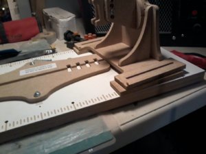
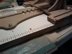
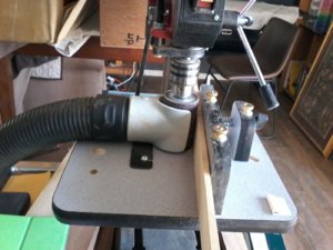
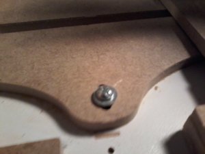
hi all, here is a pictuyre of how the building SLIP/JIG works just a test fit, after major surgery on it, LOL, still need to change the screws where i show to flat head instead iof oval head as the slip/jig gets hooked up on the oval heads, and GILLES will post more pictures t6omorrow with some questions, still making frames right now can get a complete fram in a day and a half that is a double frame i may be able to get one aday, but if not so be it they sure are much better, no need to show all the frames what takes me the longest is doing the notches, as i make the frames much thicker now i have to cut by saw the notches down to where i can use my mill to finish them
 
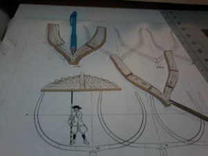
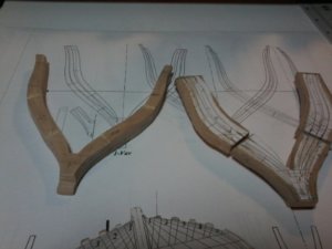
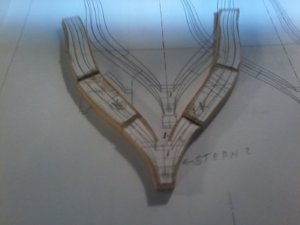
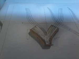
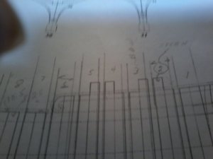
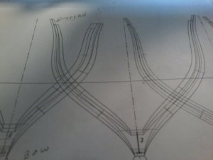
HI GILLES AND ALL, have not given up on this build in fact the frames are coming along quite nicely, only have 7 more re-dos to go, also waiting for more material from the lumberyard should be in this coming week, now for a question and some pictures again on frame No.1 witch i think is the most critcle frame as the HAWSE timbers attach to it witch makes for the entire BOW structure i show the frame including the pattern/jig for the Hawse timbers, and question on some lines that i can not understand also witch side does the short floor timber face, i think it is the stern just want to be sure 20200202_002140.jpg20200202_002419.jpg
 
HI GILLES AND ALL, have not given up on this build in fact the frames are coming along quite nicely, only have 7 more re-dos to go, also waiting for more material from the lumberyard should be in this coming week, now for a question and some pictures again on frame No.1 witch i think is the most critcle frame as the HAWSE timbers attach to it witch makes for the entire BOW structure i show the frame including the pattern/jig for the Hawse timbers, and question on some lines that i can not understand also witch side does the short floor timber face, i think it is the stern just want to be sure

Hi Don,
Good to hear that frame construction is coming along well.

Frame one: At this point, I would keep the frame "in the rough" (lots of meat on it in areas that count) but with the pattern still glued to it until you can finalize it when your hawse-timber are done: again and this is my philosophy, "better be safe than sorry", just me, others work any other way they want.

In regards to understanding the plans for your next steps, again, as I do not have the plans themselves, the only way to do this is for you to either post clear photos of the areas of the plan you need help with or to send them through messaging. Please post or send photos with only the lines from the plan, no handwritten notes. Photos showing each individual part of the plan you are having issues understanding: for example, if it is about the lines on a frame, the photo should show frame only, etc....

In regards to the Hawse-timbers, there should be a lot of information including patterns on the plans :
1) top view (as you have shown in you latest images)
2) side view
3) patterns of each individual timber, etc...
In regards to using frame 1 as a base while to work on the hawse-timbers, you are right but:
you do not need to use the frame itself (the one that will end up on you ship.
To make it easier and clearer, you may need to build a jig.
In the meantime: If you are interested in knowing how I go about doing mine on a different ship (and I still do it this way as I work mostly with "ancient" tools - No milling machine here) you can refer to the documents I wrote in the links provided earlier. Or you can click here for a direct link to the document: and go to page 110.
Again, Of course this is only my way and others surely have other ways, so I am not trying to convince anyone that it is the only or best way to do it.

In short,
1) If anyone has a different way, a better way to do it, please join in (in a positive and informative manner).

2) Yes you should be critical but critics should be made clear (avoid generic "one liners") and again, expressed in an informative manner.

Regards,
G.
 
Last edited:
Hi Don

Short timber to the stern.
I think you will benefit spending some time looking at the builds of this ship on Gerard's forum.It will give you a better understanding of the parts in 3D.You don't need to be fluent in French,the pictures are enough on their own;)
Here is the link:


Kind Regards

Nigel
 
Don,
Let me be sure I understand your question about frame 1:
you are wondering which layer of the 2 layers is facing forward? Right?

If that is the case:
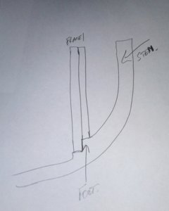
My logic would tell me that the long side is towards the stern as the frame is likely seated on a stem's rising wood: curved up towards the front so the short side should sit forward. But that is just my assumption as I do not have the plan.
The best way to figure that out is to look at the side view of the forward framing. Isolate frame 1 (the 2 layers) and look at how the frame sits on the stem. You probably see the frame sitting on stair like part of the stem at the foot of the frame: with the short length facing forward.
If you post a photo of that area, it should be easy to see.

Regards.
G.

Frame 1 foot.jpg
 
Last edited:
I feel there may be some confusion as to the question Don.Both myself and Giles are correct.Giles is right in that the stern side sits further down in the keel.As I said,the face with the smaller floor timber faces the stern.There is also a small tenon on the bow side at the base that goes into a square blind mortice in the keel.

Kind Regards

Nigel
 
For the record,
The photo above must be credited to:
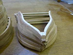
Michel M, builder of "Le Rochefort" and who, as indicated, has a building log on the "Marine et Modélisme d'Arsenal" forum.
Hopefully, he does not mind having his image shown here........
 
Don,

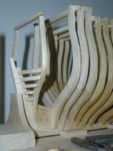
This picture from the site Nigel mentioned above may help you to visual the shape.
Keep plugging away, you'll get there.


View attachment 131307
For the record,
The photo above must be credited to:
Michel M, builder of "Le Rochefort" and who, as indicated, has a building log on the "Marine et Modélisme d'Arsenal" forum.
Hopefully, he does not mind having his image shown here........
In post #282 of this topic I mentioned already the building log and this photo by Michel...... there you can find also the link
 
Just to clarify something Don.Michel has glued copies of the drawing to both sides of the completed frame.The view on the drawing is still looking from midships towards the bow;).This has been done just to aid bevelling.

Kind Regards

Nigel
 
Back
Top