LE ROCHEFORT

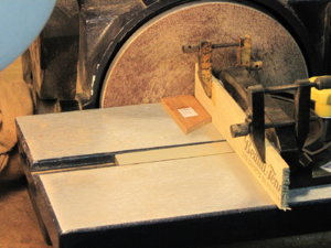
GILLES, JUST FANTASTIC ADVICE, just wonderful, not a problem with the length of the post, I THINK ALL MEMBERS especially those doing a FIRST scratch build, this is one super thread,,,,I do the frames like you suggest all except tracing paper and I will try that have some here and will get some more next saturday when i go out, i extend the joint lines but not on the PATTERN I DO IT ON THE WOOD BEFORE CUTTING THEN I USE THE DISK SANDER to get the right joint, this is the same as you suggest, i have done frame 15 and 16 will post them here soon, need some time to digest this and I am so GRATEFUL THAT YOU HAVE THE PATIENCE TO HELP ME WITH THIS SO THANK YOU AGAIN. Don
 
LAWRENCE, how would you use the miter gauge, and i only sand to the line never past it sand and fit, sand and fit as i stated above and i do as GILLES said only making the joint lines extended on the wood instead of on the pattern, and i will extend the tops as GILLES SHOWS, again all please chip in on this topic especially those getting ready to do a first time scratch build. SO THANKS TO ALL ESPECIALLY TO GILLES Don
 
THANK YOU LAWRENCE, you are using a modified Hahn method, and i am also using a modified Hahan method once I extend the top timbers as GILLES suggested, will try the miter gauge, MORE, MORE, PLEASE. Don
 
Hello Don, You are very welcome, it may seam like a pain to have to reset your miter gage to every different joint but it is well worth the effort, you will end up with great joints and no filler neaded.
Regards Lawrence

PS you can see all of the way that I built my Oliver Cromwell on my web page.
 
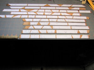
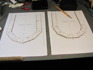
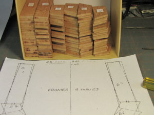
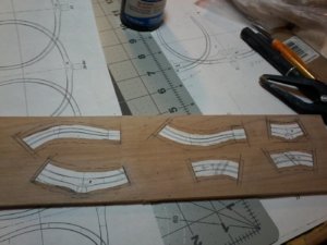
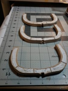
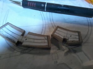
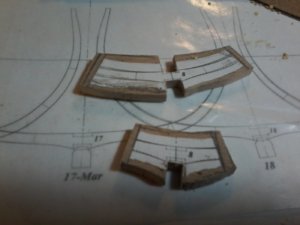
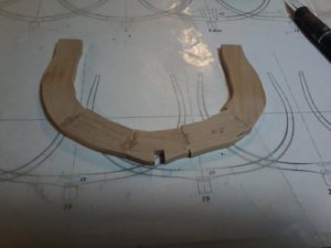
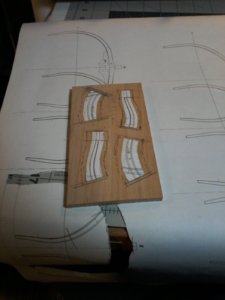
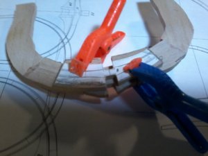
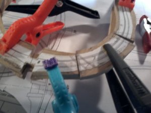
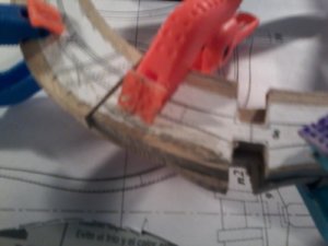
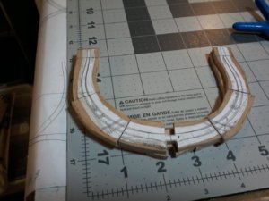
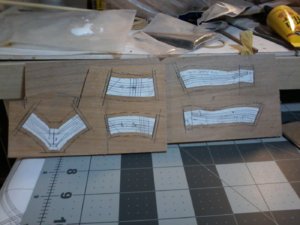
OK all i am doing FRAME No.8 showing all my steps that i do from marking the pattern on the plans to finish FRAME, so i will start this section is showing the different steps in what i am doing notice please on t6he wood where i have all frames waiting to be cut on the band saw, you can see i have added the floor timber for the second layer the reason for this is when i mill the keel notches and keelson notch i only have to do them at the same time on my mill will show those steps tomorrow, looking ahead GILLES IS SO RIGHT usin only the4 keel notches as an alaiging point is not going to work but on this FRAME I will do it the old way the next FRAME that i will do is FRAME No. 18, as i show FRAMES No. 15-17 are already done, the joints are not what i want but for right now acceptable some are tight and some are not need to get better and more consistent20200215_223643.jpg20200215_224825.jpg20200215_230545.jpg20200215_232540.jpg20200215_234048.jpg20200215_234526.jpg
 
Hello,
To anyone who would be interested in the frame building technique described in the previous page ......
As explained, the frames are double-layer frames. Most of frame layout plans show some level of individual frame edge-beveling needing to be done at some point, either during the construction of individual frames or after the hull has been assembled.
Some modelers do not worry about bevels until after assembly of the frames on the keel as the shape of the hull will be, somehow, achieved by serious sanding of the framing as a whole. In this case there is no need for the lines on the back face anyways.
Other modelers want to get a head-start with the shape of hull by applying some level of edge-bevel to each individual frame.

A question often asked is how to end up with the contour and bevel lines on both sides of the frame in a fairly accurate way and without having to transfer those lines after frame assembly.
Well, I did explain how this operation can be achieved in my previous posts (previous page).
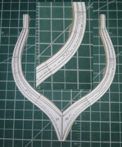
So here is the graphic representation of the result:
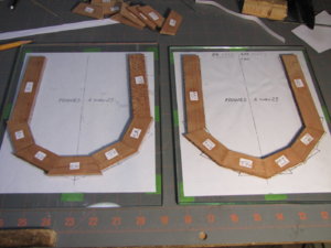
1- Assembled frame: forward face with close-up view of the lines: these are the paper patterns pasted on the wood stock prior to individual frame parts being cut and joint line sanded.
20200216_122514 copy.jpg

2 - Back face of the frame (once assembled) with close-up view of the lines once the tracing paper pattern has been removed.
This layer is the first layer to be laid over the tracing paper template. The tracing paper was used to transfer the lines on the upper face of each of the timbers forming the bottom layer of the frame: once the layers have been built, the top face of this layer is glued to the bottom face of the second layer.
The lines shown in this image are the lines traced on the tracing paper, which the frame layer was built on.
Once the tracing paper is removed from the back face of the first layer, the pencil drawn lines are still there, along with some remnants of paper and a thin layer of glue.. All can easily be removed by scraping the surface.
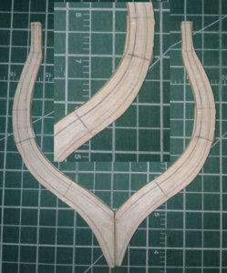
20200216_122535 copy.jpg

The base pattern is the same in laying out the different parts of the frame. First, the bottom (back) layer of the frame is precisely aligned with and glued on the pattern. Second, the forward layer is precisely laid on top of the back layer. So if the process is followed with a fair amount of precision, the lines on both faces should match.

Of course, these lines and paper patterns will eventually have to come out.
If the modeler chooses to shape the approximate bevel once the frame has been assembled but before installing the frame on the keel, the lines can be used as a reference. Once the lines are not needed and before the frame is permanently installed on the longitudinal structure of the hull, the paper and glue remnants can be scraped off the back face just as it needs to be done on the front face: removal of the pasted paper patterns.

If the modeler decides to not bother with the bevels prior to completing the assembly of the framing then the lines are not needed on either faces of each frame anyways, so they must be removed before hull assembly.
G
 
Last edited:
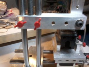
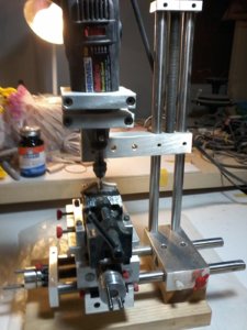
Hi again Don, its looks like your dremel is not 90% degrees, in your drill / mill rig, in the picture it looks like this.

Yesterday, I was going to make the same comment, but then I also noticed that the floor-timber in the vise seems to be angled in the same direction ...... so it looks like Don has set it up that way for some reason... he may have the part clamp at an angle following the angle the cutting bit / Dremel tool. But only HE can tell.
 
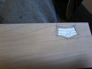
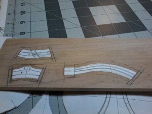
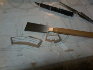
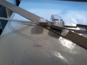
OK now showing the installation of the 2nd layer, had a problem with this as expected, found out that i needed to lower the keel notch to get both sides of the frame to work, i had to re-cut the angle of the joints in 2 places to make it right picture shows the re-work it is now ready for perliminary grinding to get the basic shape will show that in next post, also showing FRAME No.3 paterns cut and rubber cemented to the wood need confirmation of this frame as i want to be sure i understand how it goes as this is the first of the forward frames that i have done THAT IS FRAME Nos. 1-5, all help needed and all critisems wanted
 
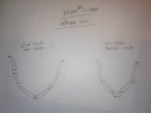
This drawing shown an exploded view of frame # 3

20200217_185431.jpg

I hope you can read it ok.

The frame composition is a bit different on the forward and aft frames.
Anyways, the first layer you would lay down is the one on the right side of the drawing: and when on the keel / rising-wood assembly, it is the layer located on the stem / bow side.
The second layer ,top layer laid down during the frame assembly, is the drawing on the left: and that would be the layer facing the stern.
Remember, when looking at the forward frame diagrams, you are standing inside the hull at mid-ship, so the face (of the frame) closest to you (the top layer during frame assembly) is located stern side.

Hope it makes sens.

The book portion of the monograph may have an exploded view showing the composition of the frame as well as explanations..... but we have already gone through here: https://shipsofscale.com/sosforums/threads/le-rochefort.3325/page-17#post-86442

Not sure how the english version of the text is presented in this monograph: whether it has images reproduced in it, or not. If not, check the french version and find the pages with comments on plates 3 and 4 which show you all the frame templates.
As far as the orientation of frame in regards to the extended top timbers on frame 3, please refer to plate 4 where you can check the hull framing. That drawing will give you that information.

G.
 
Last edited:
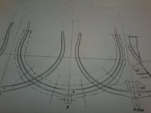
Hi GILLES HAVE A QUESTION, and some pictures, of frame 3 that i can not visulize, also on your 2 drawings, what i call the short side witch is what i am cutting out faces the stern am i right the long side faces the the stem (bow) and I THINK THAT IS WHAT IS SHOWN on SHEET 4 frame 3 top timber is facing the bow am i right in this, i have looked at the monograph and will study it some more along with your masterful work on the GROS VENTURE, more tomorrow. THANKS AGAIN Don
 
Back
Top