


- Joined
- Feb 18, 2019
- Messages
- 732
- Points
- 353

We went through this with Frame 2 here:
https://shipsofscale.com/sosforums/threads/le-rochefort.3325/page-13#post-84618
Based on that,
You apply the same principle in regards to reading the template for frame #3 after studying plate 4 to figure out the orientation of your frames.
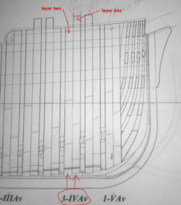
Here is a photo showing part of Plate 4.
As you can see, the longer top-timber is on the stem / bow side of the frame (#3) and face the longer top-timber of frame 2.

Now, understanding the orientation of the frame template and reading the lines shown in it in preparation for frame construction:
Again........ There are 2 points you must never forget when looking at your individual frame templates:
1- for the forward frames (for example), you are looking at the template as if you were standing anywhere around the center of the ship with your body facing the stem / bow of the vessel.
For the aft frames, you would be standing and looking at the frames from the same spot, but with your body facing toward the stern.
2- on the frame template, the solid lines represent the edges of the timbers closest to you (the viewer). As a result, the dotted lines represent the hidden edges.
You must translate the drawing into a solid 3D view of the frame: either in your head or on paper. Again, for that you can use a couple copies of your frame and colour the 2 separate layers: something similar to what Gérard did in the post linked above. For that you can also look at what other people do such as here: https://5500.forumactif.org/t2509-le-rochefort-au-1-36-par-jmau-premier-pas-en-arsenal
(when you follow this link, if you scroll down the page far enough, you will actually see a breakdown of frame 3).
Here is a comparison photo showing the image of frame 2 provided by Gérard and a image showing the template of frame 3 from your plan. Take some time to study this and train yourself in visualizing the drawings (frame templates) in 3D: it will help you for other frames as well as a few other parts needed later on.

Now, this may be obvious / logical, but maybe not, so here are the terms of reference I use when I layout my frame for construction or when I talk about it:
Layer one (1) is always the first layer to be laid down. As a result, for the forward frame (frames from mid-ship to stem), layer one is always the layer closest to the stem / bow. If I work on aft (frames from mid-ship to the stern), layer one is always be closest to the stern.
Layer two (2) is always closest to me (the viewer) and as a result is always the layer assembled on top of layer one (1).
Based on that and through the analysis of the photo above, you will note that the extended top-timber in frame 2 is closest to you or in other words is part of layer 2 when building the frame. After confirming the orientation of frame 3 as per Plate 4, the extended top-timber in frame 3 is located closest to the stem, so is part of layer 1.
_________________________________________________________________________
To build a ship, either from a kit or from scratch, the modeler must be methodical in his / her approach to the planing, the understanding as well as in the execution of the work. During the construction of a framed hull (and beyond), this methodical approach must be broken down to the level of each part needed to be shaped and assembled: from parts of a frame all the way to the finished product: a framed hull....
In short, it takes time to understand the drawings and construction should only begin after a minimum or basic understanding has been achieved.
Plan study takes time....... but it is time well spent......
G.
https://shipsofscale.com/sosforums/threads/le-rochefort.3325/page-13#post-84618
Based on that,
You apply the same principle in regards to reading the template for frame #3 after studying plate 4 to figure out the orientation of your frames.
Here is a photo showing part of Plate 4.
As you can see, the longer top-timber is on the stem / bow side of the frame (#3) and face the longer top-timber of frame 2.
Now, understanding the orientation of the frame template and reading the lines shown in it in preparation for frame construction:
Again........ There are 2 points you must never forget when looking at your individual frame templates:
1- for the forward frames (for example), you are looking at the template as if you were standing anywhere around the center of the ship with your body facing the stem / bow of the vessel.
For the aft frames, you would be standing and looking at the frames from the same spot, but with your body facing toward the stern.
2- on the frame template, the solid lines represent the edges of the timbers closest to you (the viewer). As a result, the dotted lines represent the hidden edges.
You must translate the drawing into a solid 3D view of the frame: either in your head or on paper. Again, for that you can use a couple copies of your frame and colour the 2 separate layers: something similar to what Gérard did in the post linked above. For that you can also look at what other people do such as here: https://5500.forumactif.org/t2509-le-rochefort-au-1-36-par-jmau-premier-pas-en-arsenal
(when you follow this link, if you scroll down the page far enough, you will actually see a breakdown of frame 3).
Here is a comparison photo showing the image of frame 2 provided by Gérard and a image showing the template of frame 3 from your plan. Take some time to study this and train yourself in visualizing the drawings (frame templates) in 3D: it will help you for other frames as well as a few other parts needed later on.
Now, this may be obvious / logical, but maybe not, so here are the terms of reference I use when I layout my frame for construction or when I talk about it:
Layer one (1) is always the first layer to be laid down. As a result, for the forward frame (frames from mid-ship to stem), layer one is always the layer closest to the stem / bow. If I work on aft (frames from mid-ship to the stern), layer one is always be closest to the stern.
Layer two (2) is always closest to me (the viewer) and as a result is always the layer assembled on top of layer one (1).
Based on that and through the analysis of the photo above, you will note that the extended top-timber in frame 2 is closest to you or in other words is part of layer 2 when building the frame. After confirming the orientation of frame 3 as per Plate 4, the extended top-timber in frame 3 is located closest to the stem, so is part of layer 1.
_________________________________________________________________________
To build a ship, either from a kit or from scratch, the modeler must be methodical in his / her approach to the planing, the understanding as well as in the execution of the work. During the construction of a framed hull (and beyond), this methodical approach must be broken down to the level of each part needed to be shaped and assembled: from parts of a frame all the way to the finished product: a framed hull....
In short, it takes time to understand the drawings and construction should only begin after a minimum or basic understanding has been achieved.
Plan study takes time....... but it is time well spent......
G.
Attachments
Last edited:


