
In addition to Mike's and Christian's advice, If you need to remove more material use the most outer disc surface. However, if you need jus to fine-tune the shape of your frame - use the surface close to the center of the disk sander.

-

SUBSCRIBE TO SHIPS IN SCALE TODAY!
The beloved Ships in Scale Magazine is back and charting a new course for 2026!
Discover new skills, new techniques, and new inspirations in every issue.
NOTE THAT OUR NEXT ISSUE WILL BE July/August 2026 -

Win a Free Custom Engraved Brass Coin!!!
As a way to introduce our brass coins to the community, we will raffle off a free coin during the month of August. Follow link ABOVE for instructions for entering.
You are using an out of date browser. It may not display this or other websites correctly.
You should upgrade or use an alternative browser.
You should upgrade or use an alternative browser.
LE ROCHEFORT
- Thread starter donfarr
- Start date
- Watchers 37
-
- Tags
- ancre le rochefort
THANKS ALL GUYS GOOD TIPS, WHEN I AM SADING THE ANGLES I MOVE THE PIECE FROM CENTER TO OUTSIDE EDGE (LEFT) IS THIS CORRECT. Don

THANKS ALL GUYS GOOD TIPS, WHEN I AM SADING THE ANGLES I MOVE THE PIECE FROM CENTER TO OUTSIDE EDGE (LEFT) IS THIS CORRECT. Don
On that particular sander, yes... to the left edge. On a disc sander always sand on the side where the rotation of the disc is stroking downwards.
THANKS MIKE. Don
hi all, as i said in yesterdays post still making frames if i do say so coming along OK showing pictures of recent frames and would love to here from anyone WITH COMMENTS AND CRITISIMS PLEASE, also having a qustions for GILLES OR OTHERS showing plans for starting framw 25 trough 32 asking if the center piece is split, please comments. Don
Attachments
- Joined
- Feb 18, 2019
- Messages
- 732
- Points
- 353

hi all, as i said in yesterdays post still making frames if i do say so coming along OK showing pictures of recent frames and would love to here from anyone WITH COMMENTS AND CRITISIMS PLEASE, also having a questions for GILLES OR OTHERS showing plans for starting frame 25 trough 32 asking if the center piece is split, please comments. Don
Hi Don, frames are looking good. You can probably cut the extra meat by at least half before installation.
As for your question, i am not sure as I would have to verify by looking at the plans.
FYI: I am not back home yet, Still in Central America but finally able to fly back early. Hoping to be home on Saturday... taking into account the new itinerary and new layovers.
G.
HERE IS THE PICTURE OF THE PLANS WITH MY QUESTION. Don

THANKS GILLES, please stay safe, hope this was a vacation, Don
- Joined
- Feb 18, 2019
- Messages
- 732
- Points
- 353
HERE IS THE PICTURE OF THE PLANS WITH MY QUESTION. Don
Hi Don,
Yes it is the same as the forward frames: the frame plan shows that area to be built in 2 parts assembled by a vertical joint correponding to the centre of the trapezoid timber shown in dotted line.
Did you change the configuration of the forward frames: I think the first ones you built were done in one piece? but If I also remember correctly, you were going to change that.
Regards.
G.
I have not changed it yet want to get some of the AFT FRAMES FIRST TO SEE IF I AM DOING IT RIGHT then shift to re-do forward frames still have not done frames No 1 and 2 yet, if i am correct on the aft frames they start at FRAME No. 25, HOW DID THE TRIP GO GILLES AND AGAIN THANK YOU VERY MUCH. Don

Hi Don. I think this is a great idea you have. You are definitely going to get the help and guidance you're asking for. And as you've already said, this should be of considerable service to others who would like to perhaps get into their own first scratch build or POF build. I look forward to following your progress. By the way, if you aren't completely happy and comfortable working with metric dimensions, then don't. When I was starting my current project, I realized that the dimensions were all in the historical Pied Du Roi, in which one foot equals 12.789 inches. I thought I was in big trouble unless I could find appropriate measuring tools. I even tried to buy some until I realized the truth. You can simply use your own preferred scales to capture the dimensions you need directly from the drawings. Obviously, for now you'll just need to get the dimension you need to locate material for the keel structure and frames.
Hi JIM I THANK YOU FOR YOUR RESPONSE, AT ONE TOME I WAS WORRIED ABOUT USING METRIC, but with a good CALIPER that has digital in feet, fractions and metric so far has been working out for me, i do order my materials in FRACTIONS (LUMBERYARD) i try to get it a little thicker then use my thickness sander to get it to METRIC, so far it is working, IF YOU ARE INTERESTED IN THESE TYPE OF BUILDS AND ARE THINKING ABOUT A FIRST TIME POF OR A FIRST TIME SCRATCH HERE ARE SOME HELP ITEMS I DO NOT KNOW HOW TO GIVE YOU LINKS but here are the items for my LE ROCHEFORT AS A COMPLIMENT TO THE FANTASTIC MONOGRAPH AND PLAN SETS BY GERARD GILLES HAS A REALLY FANTASTIC WHAT I CALL A PRACTORIUM FROM HIS GRO VENTURE PRODUCT HE GIVES A LINK ON MY BUILD IT IS CALLED THE SHIP WAY NEWS A IT IS GIGANTIC AND CLERARLY UNDERSTANDABLE IT IS PDF AND FREE TO BOOT, if you are looking for afirst time POF I CAN NOT THINK OF A BEETER ONE THEN THE CAUSTIC (LUMBERYARD) WITH U TUBE INSTRUCTIONS IT IS ON MSB I DID NOT KNOW IF I WOULD BE ABLE TO DO THIS BUT GUESS WHAT HOOKED, HOOKED and HOOKED, and i welcome all comments and espoecially critisims only way to learn. Don PS LOOKING FORWARD TO YOUR COMMENTS. THANKS Don
Hi Don. I think this is a great idea. You'll get the help you are asking for - that's for certain. And it will be encouraging to other members who would like to start their own first scratch build or p.o.f. build. I am looking forward to following your progress!
I might be misunderstanding your question about metric dimensions, but I would just say that, if you aren't completely happy and comfortable working with metric dimensions on this build ---- don't. When I was planning my current build, and realized that all the dimensions were in pied du roi, I thought I was in big trouble. Pied du roi is the historical french dimensional system in which 1 foot equals 12.789 inches. I actually tried to purchase the appropriate measuring devices before realizing the logical truth. You can use any dimensional system you like WITH EASE. Just use your own measuring scales, gauges, micrometers, whatever, and take all needed dimensions directly from the drawings. Obviously, all you need at first are the key thicknesses of material for the keel structure and frames.
I might be misunderstanding your question about metric dimensions, but I would just say that, if you aren't completely happy and comfortable working with metric dimensions on this build ---- don't. When I was planning my current build, and realized that all the dimensions were in pied du roi, I thought I was in big trouble. Pied du roi is the historical french dimensional system in which 1 foot equals 12.789 inches. I actually tried to purchase the appropriate measuring devices before realizing the logical truth. You can use any dimensional system you like WITH EASE. Just use your own measuring scales, gauges, micrometers, whatever, and take all needed dimensions directly from the drawings. Obviously, all you need at first are the key thicknesses of material for the keel structure and frames.
all right starting to wind down the first phase of the frames, from FRAME No. 25 through 32 are V shaped as well as some BOW frames that i have to re-do not to many and require the frames to be cut vertically as well as horizontal picture showing FRAME No. 25 to verify if i am correct, as described in another thread the way i intend to do this, it is not the best so if GILLES AND OTHERS HAVE BETTER SUGESTIONS PLEASE, PLEASE COMMENT, also i need to verify something with the frames as i am doing them they are working out OK for now but not sure if it is acurate enough, i am using the keel notches as a starting point for both the first layer and 2nd layer of the frames there must be a more accurate way to do this

- Joined
- Feb 18, 2019
- Messages
- 732
- Points
- 353
The two timbers in question can be made in 1 part, then cut apart using any saw. Of course, in proportion with the size of the timbers: you would not want to use a full size table saw to cut this tiny piece, potentialy loosing 1/8" material on the cut line: as a result, you would end up with a narrower total spread at the extremities.
So use any thin blade. Once cut, if you do not do anything to the 2 surfaces to be joined, your joint will be prety much invisible: Which kind of defeat the purpose of cutting the original part in 2 in the first place.
If you leave the V shape in 1 piece, you can simmulate the joint by just running a sharp blade over the joint line a couple times: lightly.
It does not really matter, as these joints will be hidden from view. check the plan, but if I remember correctly, you will need to install a filling timber at the base of the frames between the keel and keelson: although this may exclude the stern most and fore most frames. please double check.
If it were me.... I have personaly made the V shape of such frames in two separate parts in the past, especially when working from the type of monograph you are working from: but i am sure you would not be the first person to not do it if you choose.
G.
Last edited:
THANKS AGAIN GILLES, I AM STILL NOT SURE OF HOW YET, WILL FIGURE OUT WITCH WAY TO GO, TODAY, THE IDEA OF SCORING IS A GOOD ONE, plan to do that with the bow sections, WHAT IS YOUR RECOMANDATIONS I WOULD DO THE CUTS IF I WAS NOT LEAVING A LOT OF MEAT ON THE FRAMES, WITCH IS WORKING OUT QUITE WELL FOR ME,,,,ALSO WHAT ABOUT THE KEEL NOTCHES AS A STARTING POINT FOR THE FIRST AND SECOND LAYERS IS THERE A MORE ACURATE WAY OF DOING THIS. THANKS AGAIN Don
Hi all finally bit the bullet and started the frame No.25, so how i decided to do these V FRAMES ON THE AFT SECTION is To do as i previoulst did my frames with plenty of meat and keel notches i then score a horizantol line where the cut goes with a marking knife and and x-act blad and using my SMALLEST DOUZUKI (JAPANNESSE SAW) and just started the cut will finish the cuts afterall pieces are dry fitted then i will make the cuts LORD WILLING I CAN DO THIS NEED TO LEARNHOW THESE THINGS ARE DONE IT IS ANOTHER STEP UP THE LADDER 

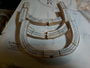
hi all well i did the V SECTIONS AS SUPOSED TO BE DONE (I THINK) pictures showing how i did it, the overall first layer is correct in its placement, after verifying the placement i removed the floor timber and very carefully scribed the dotted line with a marking knife and an exacto blade several times then using my JAPANESSE SAWS THE VERY FINE DOZUKI to start my cuts unfortunaly it is to small to go very far but CREATES a good start then follow up with my other JAPANESE SAW being very careful have to be ver, very, careful how you position the timber in the vice the final cut is the vertical one with the dozuki and finally dry fitting the pieces together, hope this is correct, again comments and critisisms


- Joined
- Feb 18, 2019
- Messages
- 732
- Points
- 353
hi all well i did the V SECTIONS AS SUPOSED TO BE DONE (I THINK) pictures showing how i did it, the overall first layer is correct in its placement, after verifying the placement i removed the floor timber and very carefully scribed the dotted line with a marking knife and an exacto blade several times then using my JAPANESSE SAWS THE VERY FINE DOZUKI to start my cuts unfortunaly it is to small to go very far but CREATES a good start then follow up with my other JAPANESE SAW being very careful have to be ver, very, careful how you position the timber in the vice the final cut is the vertical one with the dozuki and finally dry fitting the pieces together, hope this is correct, again comments and critisismsView attachment 138973View attachment 138974
I may be wrong but..... Looking at theses2 images, it looks like you cut the bottom triangular or trapezoid piece (drawn in a dotted line on your plan) in 2 pieces verticaly: in the center of the notch. This piece, which is part of your first layer should be in 1 piece: no vertcal joint.
For a good view of what the base of you frame should look like, go back to page 21 of your log and check the second photo included in post # 412 (exploded view). The only difference between this drawing and your frame is that in you frame (#25), the triangular part is in 1 piece, and you can see that there is no vertcal joint in it. The first layer of the frame, the layer closest to the stern, or the bottom layer of your frame is composed of parts 9 and 10 in that drawing.
The vertical joint is placed only in the foot of the second layer: represented with #8 in the referenced drawing.
I hope this makes sense.
Let us know if this make sense.
I should finally be home tonight, and I will post a breakdown of the parts of your frame sometimes today or next morning.
Regards.
G
THANKS GILLES, i think it makes sense if iunderstand correctly the first layer has only the horizantal piece cut no vertical cut, the second layer has both the vertical cut and the horizantal cut am i correct, to bad i was proud of it oh well this is why you learn from your mistakes. THANKS AGAIN Don