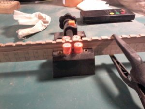
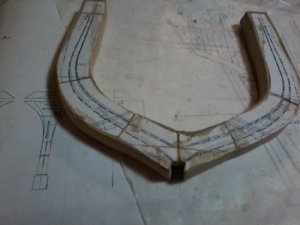
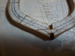
OOPS NO HORIZANTAL CUT IN THE SECOND LAYER JUST VERTICAL HOPE I GOT IT THIS TIME, OLD SAYING CHECK DETAILS 3 TIMES CUT ONCE LOL ANOTHER LEARNING EXPERIENCE. THANKS AGAIN Don
-

Win a Free Custom Engraved Brass Coin!!!
As a way to introduce our brass coins to the community, we will raffle off a free coin during the month of August. Follow link ABOVE for instructions for entering.
-

PRE-ORDER SHIPS IN SCALE TODAY!
The beloved Ships in Scale Magazine is back and charting a new course for 2026!
Discover new skills, new techniques, and new inspirations in every issue.
NOTE THAT OUR FIRST ISSUE WILL BE JAN/FEB 2026
You are using an out of date browser. It may not display this or other websites correctly.
You should upgrade or use an alternative browser.
You should upgrade or use an alternative browser.
LE ROCHEFORT
- Thread starter donfarr
- Start date
- Watchers 37
-
- Tags
- ancre le rochefort
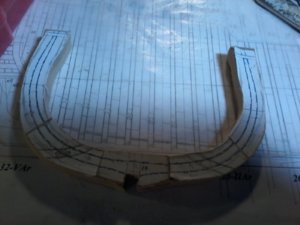
HERE IS PICTURE OF CORECTED FLOOR TIMBER FOR FIRST LAYER I think this is correct (HOPE SO THIS TIME IT IS DRY FITTED AND NOT GLUED YET waiting for confirmation that this is correct. THANKS Don
- Joined
- Feb 18, 2019
- Messages
- 717
- Points
- 353

AS ALWAY GILLES SUPERB, SUPER AND I UNDERSTAND IT, on to finish up FRAME No.25, THANKS AGAIN Don will post completed frame picture latter, this is amazing fun right now and a learning experience. THANKS Don
- Joined
- Feb 18, 2019
- Messages
- 717
- Points
- 353

FYI:
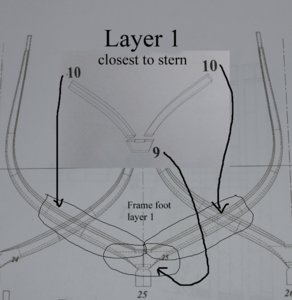
Aft frames, first layer: closest to the stern and drawn with dotted lines,
The "V" shape foot (marked as 9 in the view above) is composed of:
- 1 piece for frame 25, 26 and 27
- 2 pieces for frame 28 and 29 (horizontal joint between the 2 parts)
- 3 pieces for frame 30, 31 and 32 (horizontal joint between each part)
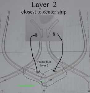
Aft frames, second layer: closest to center-ship (marked as 8 in the view above) and drawn with solid lines:
- same for all frames - 2 parts assembled with a vertical joint.
On a side note, I am sure you already noticed that frame 25 / 26 and 29 / 30 have extended top-timbers: same as you saw in the forward frames and you should not have a problem figuring out on which layers these extensions go.
Have not check the foot of the forward frames but the same setup should apply: and maybe we will see when you get there.
Regards.
G.
AGAIN THANK YOU GILLES ONE QUESTION, on of to forward frames d o not remember witch one will check the TOP TIMBER extension DID NOT MATCH UP WITH THE HEIGHT FROM THE FRAME PLAN TO THE DETAILS ON PLAN SET 4, YOU SAID TO LEAVE IT ALONE FOR NOW, IF THE DIMENSIONS ON THE TOP TIMBERS MATCH FRAME PLAN TO DETAIL SHOULD I CUT IT TO CORRECT HEIGHT NOW OR WAIT. THANKS AGAIN Don
- Joined
- Feb 18, 2019
- Messages
- 717
- Points
- 353

ONE QUESTION, on of to forward frames d o not remember witch one will check the TOP TIMBER extension DID NOT MATCH UP WITH THE HEIGHT FROM THE FRAME PLAN TO THE DETAILS ON PLAN SET 4, YOU SAID TO LEAVE IT ALONE FOR NOW, IF THE DIMENSIONS ON THE TOP TIMBERS MATCH FRAME PLAN TO DETAIL SHOULD I CUT IT TO CORRECT HEIGHT NOW OR WAIT. THANKS AGAIN Don
Hi Don,
I am quite confident that the difference in height will work out fine: it could be due to the the position of a deck beam. If I remember correctly, it was not the extension itself that was too long, but the difference was in the measurement between the short end of the top-timber on one layer of the frame and long end on the other top-timber on the layer layer that seem odd or irregular.
G.
YES GILLES THAT IS CORRECT, WILL NOT WORRY ABOUT IT NOW, FINISHED UP ON FRAM No.25 starting on 26 will post pictur I AM QUITE PLEASED WITH THEOUTCOME OF SOMETHING I HAVE NEVER DONE BEFORE IF IT IS WRONG TELL ME PLEASE. Don
picture of frame No. 25 showing correct way, i think of doing floor timbers, the 2nd layer photo shows a vertical line did not do just VERTICAL
- Joined
- Feb 18, 2019
- Messages
- 717
- Points
- 353

Hi Don,
First layer (closest to the stern)??
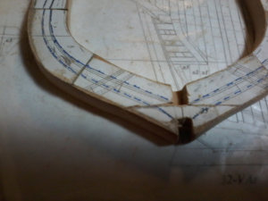
Second layer (closest to mid-ship)??
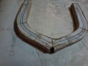
Looks good.
Critique:
Some joints do not form continuous contour lines from futtock to futtock on both layers : but that is alright as you can compensate when time comes to sand closer to the lines (when you remove the extra meat around the frame).
Now, I have a question:
How are you going to line-up and assemble the 2 layers to make one 2-layer frame?
G
First layer (closest to the stern)??

Second layer (closest to mid-ship)??

Looks good.
Critique:
Some joints do not form continuous contour lines from futtock to futtock on both layers : but that is alright as you can compensate when time comes to sand closer to the lines (when you remove the extra meat around the frame).
Now, I have a question:
How are you going to line-up and assemble the 2 layers to make one 2-layer frame?
G
OK GILLES, THAT IS A ON GOING PROBLEM as you can see frame No.25 is now complete how i have been doing that to me is totaly unaceptable and inaccurat I HAVE BEEN USTING THE KEEL NOTCHES AS A STARTING POINT ON THA FIRST LAYER IT WORKS QUITE WELL IT ALL LINES UP AND I AM MAKING SURE that the tops fall in line with the plans , the second layer is a problem i have been able to work it out but just to me not accurate i hve been using the keel notches from the first layer floor timber to line up the second layer floor timber leaving the amount on the keel as required by plans then fitting the futtocks an top timbers along the blue outline lines and aligning them with each other sometimes the fall right into place, and sometime they require fittting before placing all the while checking that the tops are in line, there has to be another way to do this that assures accuracy, how do you do it, also what i am now doing is making sure that both interior and exterior extra meat on all sides are even, this should help when i start to finish up frames will have to go back and adjust some frames also going to glue extenstions to the top of frame to give me more meat to get them exact filler will not show will be cvered by planking on both exterior and interior i only plan on one or 2 strips of planing but doing the wales with a couple of strips above wale and below., LONG THREAD HOPE I AM EXPLAINING MYSELF PROPERLY. THANKS AGAIN Don
- Joined
- Feb 18, 2019
- Messages
- 717
- Points
- 353

OK GILLES, THAT IS A ON GOING PROBLEM as you can see frame No.25 is now complete how i have been doing that to me is totaly unaceptable and inaccurat I HAVE BEEN USTING THE KEEL NOTCHES AS A STARTING POINT ON THA FIRST LAYER IT WORKS QUITE WELL IT ALL LINES UP AND I AM MAKING SURE that the tops fall in line with the plans , the second layer is a problem i have been able to work it out but just to me not accurate i hve been using the keel notches from the first layer floor timber to line up the second layer floor timber leaving the amount on the keel as required by plans then fitting the futtocks an top timbers along the blue outline lines and aligning them with each other sometimes the fall right into place, and sometime they require fittting before placing all the while checking that the tops are in line, there has to be another way to do this that assures accuracy, how do you do it, also what i am now doing is making sure that both interior and exterior extra meat on all sides are even, this should help when i start to finish up frames will have to go back and adjust some frames also going to glue extenstions to the top of frame to give me more meat to get them exact filler will not show will be cvered by planking on both exterior and interior i only plan on one or 2 strips of planing but doing the wales with a couple of strips above wale and below., LONG THREAD HOPE I AM EXPLAINING MYSELF PROPERLY. THANKS AGAIN Don
Hi Don,
Personally, I would remove the paper from the first layer and rely on the placement of the joint as well as the notches to line everything up and this stage.
The joints will give you several references. To line up the joints, extend the joint lines from a frame paper template so that the lines are seen past the "extra meat" you left, place the assembled first layer over the template lining up the joints. Then place your second layer over the first, again lining up the second layer joints with the frame paper template. Try this with the paper still glued to the first layer. If your joints line up, remove the paper, dry fit again and if satisfied, glue the 2 layers together. It should work. Just make sure you do all this looking at the fit from directly above: looking straight down at your work.
On a side note, AVOID USING CLAMPS as the 2 layers may slightly slide from each other and you will loose the alignment. Using clamps means that you must hold the assembly in your hands and that is not a good idea. Better use a weight on top of the frame: the least amount of handling the better.
I have explained how I build frames here ( https://shipsofscale.com/sosforums/threads/le-rochefort.3325/page-18#post-87714 ) but you noticed that I do not use paper patterns on my first layer, so you are using a slightly different method
But let us take advantage of experience from other modelers...
I have posted a general request for help from other modelers here:
Help - Building frames for ship built from plans
Hello, Please, we need your help... One of our fellow modelers is having a dilemma building frames for his model. The construction of his frame is the traditional 2-layer frame. To familiarize yourself with his project, here is the building log...
shipsofscale.com
Regards.
G.
PS: this kind of problem is actually a good example showing why it would be nice to have a forum organized in a way that information would be indexed by topic or subject related to scratch build ship parts: to make it easy for members to find. This kind of info database could be built over time. Should a member be in need of info regarding most ship building subjects, indexed and linked to each other: it would be called "PofModelshipedia" (I will retain the copyright for this name
Last edited:
Hi GILLES YOUR SUGESTION ABOUT OTHERS IS A FANTASTIC IDEA AS YOU KNOW AFTER EVERY POST I ASK THAT, YOUR REPUTATION IS BETTER THEN MINE WHY NOT TRY TO PERSONALLY CONTACT MEMBERS YOU ARE FAMILAR WITH LIKE UWE, MAYBE EVEN GERARD, AND I WILL DO THE SAME WITH DAVE STEVENS AND OTHERS IS THAT ACCEPTABLE TO YOU,,,,,,, YOUR SUGESTIONS IS A WODRRFUL IDEA I NEVER THOUGT OF THT MY ONLY PROBLEM AS I SEE IT IS REMOVING PATTERN I THEN LOOSE THE IMPORTANT LINES TO SAND,,,,,,,,, ONE OTHER PROBLEM RIGHT NOW IS DAVE STEVENS IS ON SHUT DOWN BY GOVERNMENT NO SHIPPING OUT OF FRAME MATERIAL HAVE ENOUGH FOR JUST 2 more frames, then a decision to what to do should i go back and start the second sanding on all that i have, or look at some other section to do like maybe some interiors YOUR ADVICE PLEASE. THANKS SO MUCH Don
ok guys, here goes no soap box now only one comment I DO HAVE PHYSICAL PROBLEMS THAT I HAVE TO ADAPT TO,NO COMPLAINTS BECAUSE I THAN JESUES FOR WHAT I HAVE TODAY, just briefly can not stand without holding on to something, eyesight is not that great, hand eye coordination is not what it once was, and very bad ARTHRITS and i do mean bad at times, have not been able to drive for ove 7 years out only once a month 4 hours by son-in law, so it is what it is this is more then a hobby to me it is my life right now and i have to adapt in different ways so no mor BS PICTURES SHOWIN ONE FRAME BEING WORKED ON HAVE GOT IT TO HALF THE MEAT THAT WAS THERE NOW JUST TO EVEN IT UP AND PUT IT AWAY FOR DISCUSSION WITH GILLES AND ANY ONE ELSE WITH USEFULL CRITISIMS AND PLEASE, PLEASE COMMENT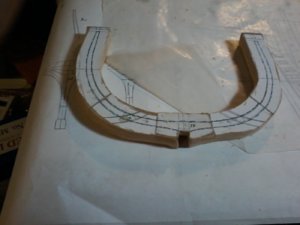


- Joined
- Feb 18, 2019
- Messages
- 717
- Points
- 353

Looks like you got both layers lined up and glued together, so you are good to go...
THANKS GILLES, i did this just as a sample to show the PROCESS, just need to even all sides up and put it away, HOW MUCH MORE SHOULD I TAKE OFF BEFORE BEVELING. THANKS don
- Joined
- Feb 18, 2019
- Messages
- 717
- Points
- 353

THANKS GILLES, i did this just as a sample to show the PROCESS, just need to even all sides up and put it away, HOW MUCH MORE SHOULD I TAKE OFF BEFORE BEVELING. THANKS don
Well!
The more meat you have around the frame, the more work to do to get the bevels in.
I would suggest that you reduce the meat by at least half, if not more.
Then, if you decide to work on each individual frame, you will have to somehow transfer the bevel lines onto the bottom layer: the opposite side of the frame.
Furthermore, the lines on the front of the frame needs to line up with the pattern you need to transfer on the opposite side.
You cannot do the bevel just by eye. You need lines to guide you.
Will you need help with transferring the lines?
The other solution is to forget about the bevels until the framing has been assembled. You would then sand the assembled framing (including filling pieces) achieving the all the bevels at the same time.
For that, you would have to further reduce the amount of extra material around the frame so that you will not spend days sanding the entire framing assembly, or break anything while doing it.
It is easier and faster to bring individual frames closer to the line, than it is sanding down the assembled framing. In this case, I would not leave much more than 1 mm meat. At this point, it looks like you have 5 or 6 mm extra on each side of the frame (inside and outside).
Again and as always, other members may have other solutions to be applied considering the context of your build and the work you have already done.
G.
Last edited:
OH YES I WILL SURE NEED HELP IN TRANSFERING THE LINES, AND I WOULD LIKE TO DO MOST OF THE BEVELING OFF THE MODEL AS MUCH A S POSSIBLE AFRAID OF BREAKAGE ESPECIALLY THE THIN TOP TIMBERS RIGHT NOW FRAME No.19 IS JUST A TEST I AM GOING TO EVEN UP ALL THE SIDES, THEN FINISH UP THE FRAMES AS FAR AS MY MATERIAL WILL ALOW. Don WILL POST PICTURE OF TEST FRAME,,, I AM NOT LOOKING FORWARD TO BEVLING BUT IT IS TIME TO LEARN THIS I HAVE NEVER LEARNED TO BEVEL FRAMES BUT REALLY WOULD WANT TO DO IT OFF MODEL. THANKS Don


