LE ROCHEFORT

ok more up date first layer, showing the procedure cutting pieces on band saw leaving a little more meat witch will be sanded down in the first rough sanding, also the notches because o all the meat left on i can not mill it that way to much meat, so what i do is first make a series of cuts with japanese saw to a certain dept clean it up with files do another series of cuts closer to the line then put it in the mill fo final cut i take very shallow cuts some times it take a couple of passes, i carry the blue mark down the sides to mark the lines you see the joints sanded on the disk sander, tomorrow showing how i put the first layer together, on top of frame layout over wax paper using pins again all comments needed please, you see something wrong say it, if a better way say it that is called learning20200327_011939.jpg20200327_013236.jpg20200327_014304.jpg20200327_014304.jpg20200327_014556.jpg20200327_020551.jpg20200327_021846.jpg20200327_022231.jpg20200327_022425.jpg20200327_023748.jpg
 
more pictures on the first layer ( NORMALLY IT DOES NOT TAKE THIS LONG, BUT PICTURES ARE DOWN TIME) so showing the floor timber pined in place 2 pots of refrence keel notch and the blue line markings, the critical part is the top also affects the height being the same on both sides and bouth layers then all parts pinned onto frame plan, one top timber is out of whack, just a small joint plan was out very , very, little it does not take much to through the whole thing out this is what happen on the second layer, so guys as GILLES SAID COME TO RESCUE WHEN I START THE SECOND LAYER LATTER TODAY the next step for the first layer is to cut the horizanta piece of the floor timber and gle that togethe then glue the complete first layer20200327_182354.jpg20200327_182612.jpg20200327_183432.jpg20200327_185711.jpg20200327_185802.jpg20200327_185943.jpg
 
OK ALL showing the completion of the first the tool storage is used as a weight to hold down the first layer until glue dries, the patterns of the second layer glued to board ready for cutting this is where i am having difficulties, will show my method and GILLES SUGESTION, GILES I WILL TAKE PICTURE OF BOTH THE FRAMES THE OLD ONE AND THE REDO, this is when you came in to set it straight none those frames worked out the joints were terrible done by hand before disk sander need your help on this one let me here Don
 
IT IS ONE OF MY FIRST ATTEMPTS

Why is it still laying on the bench.? Don, you always say you don't have enough space. You need to tidy up some!!! I have found that I can really only hold one maybe two tools at a time. The rest of the workbench should be clean bro!!!
 
If I may make a suggestion in regards to weight on top of the frame while the glue dries:
Not sure the plastic box directly on the frame is such a good idea. You should use something stiff and flat as a base to put some weight on , something that does not flex: such as glass, MDF, 1/2" plywood for example. Then stack some weight on top, so that the weight / pressure is evenly distributed on the entire frame.
It is not critical, just good practice.
G
 
Hello Mike MY HOBBY ROOM RIGT NOW IS A DISASTER TOTAL DUST FROM BAND DUST FROM SANDER etc, quick explanatio remdeling is being done but held back because my daughtwer and son- in-law grandsons are all under 14 day selff quaranteen travels through CO, UTAH, THEY ARE AL MOST FINISHED WITH THIS long story sho
 
you are right igiles when i can get out i have some ply wood 3/4 inch and some used bricks that i intend to use, ok , ok, now for my problems and do need help on this one i am going to be showing pictures of first layer of frame no.27 complete thatis what the tool box is on check out both front with the pattern an back showing joints NOW FOR THE BIGGIE I SHOW FIRST THE WAY I HAVE BEEN attaching layer 2 to one by useing the keel notch as a starting point not working out, now i normally with a lot of adjustments wit the floor timber and checking the two side of futtocks etc to see if they are the same in length, they normally are, now using what i thougth would work by turning over the first layer making sure it is in line and extending the joint lines on the plansof 2nd layer as you see in the picture disaster one side ok the next poof, now i can fix this again using what i said above but there must be a moire accurate and better way to do this so need hep to get it right good time to do this as out of frame material here are the pictures no oops this time20200328_034114.jpg20200328_034257.jpg20200328_035338.jpg20200328_035418.jpg20200328_040322.jpg20200328_042250.jpg20200328_044105.jpg
 

Attachments

  • 20200328_044801.jpg
    20200328_044801.jpg
    140.1 KB · Views: 1
GILLES one picture shows a bunch of zip lock bags THOSE ARE ALL THE REDOS SINCE YOU CAME ABOARD SAVED ALL OF THE OLD ONES FOR REFERENCE AS NEEDED, maost of these redos are fault joints before i got my disk sander doing by hand no go some could be used but my standards have expoaned what i would have used 8 or 9 monts ago i will NOT USE TODAY PERIOD now help to get this out of the way another learning process and i will start doing all frames done so far to 3mm meat on both sides as shown before on frame 18 and also practing on bevels trying understad the lines and procdures, and one last note i will go with yours, nigel and marrateen sugestion to do the final beveling on frames after all are attched to the keel, one other not on the building slip/jig i have ordered from hooby zone americian distributor hobbyworld the smaller building/ slip/jig but they are out of stock in POLAND, hoprfully in soon, that should work better for me in weight and manuverability. ENOUGH TONIGHT, TIRED Don
 
Hi Gents,

I haven t read all posts up to now so maybe a stupid remark from my side, so upfront sorry for that.

If you have the 6,5 mm extra meat on the frames and the fairing is done when the hull is assembled why not glue the two layers together and then mill the keel notch. In this way both frames do have exactly the same fit and alignment. The two frame sections will be one frame any way after assembly.
The only importance is to get a proper fit between the but ends of the frame sections.

Just a thought.
 
Thank you @Olivers Historic Shipyard .
That is a great solution.


Thank you @Maarten,
To ease the process, this is also a very good solution.

________________________________________________________________________________________

So now that we have Don’s step by step view of the process he uses, we can analyze so that HE can find appropriate solutions with the help of the membership: this is not a case of “it is my way, the best and only way”. I am sure HE sees this as learning by trials and errors: which is what most modelers ends up doing.

The first step is: Don has to understand why it is not working so well for him so that the method can be adapted to fit his goal. From there and complemented with constructive guidance, almost everything should fall in place and he should find needed solutions.

Here is my first obvious observation after looking at the process and the results shown in images.
The main reasons why the 2 layers do not match: accuracy and symmetry.

Everything starts with the accuracy of the angle in the joints between parts of the frame. From there, every other error compounds any negative effect. The lack of accuracy in the angle of the joints results in the lack of symmetry in the sides (port / starboard) of the fame.

So to begin with … One more reference point you may utilize.

Frame 15 copy.jpg

Furthermore, as indicated throughout previous explanations, the secret is to not rush through the process. But it is to make sure the first part lines up with the drawing (plan), the second part lines up with the first and the drawing. It is somewhat meticulous but needed. Using this approach for every part, all the way up the frame will ensure everything is as per the plan: the ultimate goal being to achieve symmetry between the two sides (again, port and starboard sides) of the frame: starting with layer one.

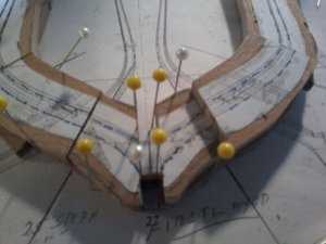
Beveling the edges of the frame requires reference lines on both sides of the frame (forward and aft).
Having paper patterns used to line up the parts for the 1st layer, requires flipping this layer upside down or removing the paper in order to not sandwich paper between the 2 layers.
To ensure that the lines (paper patterns) used to build the 1st layer follow the plan when you flip it upside down, the 2 sides of the frame, port and starboard sides, need to be symmetrical: if not your built layer will not match the plan anymore.
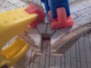
Because you loose all reference lines after the layer is flipped upside down, you now need to rely on joint lines and maybe the notch to line up the second layer on top. If your joints are not accurate, and your first layer is not symmetrical from side to side, you will end up with the problems you are encountering at this point.

Now, as you have decided to do the beveling, as suggested, only after the frames are installed onto the keel, this simplifies the process for the second layer.
You only need to make sure the parts of the second layer fit within the overall shape of the 1st layer.
As you are leaving a lot of meat, this should not be too much of a problem. You may also be able to work with some of your bad frames as well.
You are going to ask about the notches that have already been cut... well, I am sure we can find a solution to work with that.

Once your 2 layers are assembled, you can reduce the meat around using the contour lines still glued to your 1st layer. But again that layer needs to be accurately built (symmetrical from side to side. The extra meat will be used to compensate for any small errors as long as the notches are also placed accurately: whether they have already been cut or cut later.

On a side note, as you still would like to practice bevels on individual frames, do not throw away the bad frames, you can use those.

Again sorry for the long post...


G.
 
Last edited:
OK THANKS GUYS, 20200328_070140.jpg20200328_070140.jpg the proposals so i can understand them, in the mean time pictures showing adjustments made to floor timber an i would still have to slightly adjust the joints of the futtocks and it is there, but what i am asking here is a better more accurate way to do this, so help needed, guys something happened on the pictures i can not get the other picture to post will not move do not know what is happening
 

Attachments

  • 20200328_070304.jpg
    20200328_070304.jpg
    128.6 KB · Views: 3
Don,
Again, in this case, as per the last photos you posted:
you are adjusting the position of the 2nd layer (top layer) "floor-timber" (the foot of the frame) as well as leaving gaps between the different parts to allow you to line up the futtocks within the 1st layer overall pattern.
Knowing that the contour lines that guided you to build your first layer are now invisible, as they are located on the back face of the first layer that has been flipped, you are left with trying to line up the 2nd layer (top layer of the frame) with no concrete guiding lines / references: except for joint and notches.

Knowing that these references, the joint lines and notches, are possibly inaccurate and knowing that in the end, the 2 sides of your first layer may not be symmetrical, aligning the 2 layers is not reliable, if not impossible.

In this case, you are back to what I was saying in my last post:
"Now, as you have decided to do the beveling, as suggested, only after the frames are installed onto the keel, this simplifies the process for the second layer.
You only need to make sure the parts of the second layer fit within the overall shape of the 1st layer."

This really means that you basically cut "blanks" from the 2nd layer patterns following the appropriate and accurate joint-line angles. You do not even need to use a second set of contour lines on that 2nd layer. You then glue the blanks to the first layer: that will make members promoting frame construction from blanks happy (sorry, could not help it) as you will have officially built a frame using both methods. ;)
Once the glue is dry, you can use the contour lines still on the 1st layer to square the edges of you frame closer to their final dimension: leaving more or less 2mm extra meat around.

Again, a very important note:
Before you square the edges or even before you assemble the 2nd layer with the 1st layer and possibly rework the notches, you need to make sure that the 2 sides of you frame (1st layer port and starboard sides) are symmetrical from the center line shown in my last post. This step can be easily done once the 1st layer has been assembled and before you glue the 2nd layer on. It should give you a fairly accurate foundation to glue the 2nd layer on.
Please ask if you need help with that.....

As far as the notches, we can discuss that afterwards.
For the time being, you need to concentrate on the accuracy and symmetry within the first layer.

I hope this makes sense as this is improvisation.
Someone may have a better way to explain.

G.

Building frames any way is usually quite straightforward. I think we are getting close to being able to write a book about it.

Maybe, just maybe, we should set up a conference call...
 
Last edited:
Back
Top