
-

SUBSCRIBE TO SHIPS IN SCALE TODAY!
The beloved Ships in Scale Magazine is back and charting a new course for 2026!
Discover new skills, new techniques, and new inspirations in every issue.
NOTE THAT OUR NEXT ISSUE WILL BE July/August 2026 -

Win a Free Custom Engraved Brass Coin!!!
As a way to introduce our brass coins to the community, we will raffle off a free coin during the month of August. Follow link ABOVE for instructions for entering.
You are using an out of date browser. It may not display this or other websites correctly.
You should upgrade or use an alternative browser.
You should upgrade or use an alternative browser.
Medieval Spanish Coca - AMATI 1:60 [COMPLETED BUILD]
- Thread starter Michiel de Ruyter
- Start date
- Watchers 21
- Joined
- Feb 15, 2021
- Messages
- 97
- Points
- 143

THANKSSSSS! VERY SUPER SUPER INTERESTING!!!!!!!
Rodolfo
Rodolfo
- Joined
- Feb 15, 2021
- Messages
- 97
- Points
- 143
Welcome, dear friends!
The work continued with the laying of the shrouds, according to the following drawing, found in Pino dall'Orco "Sartie, stile mediterraneo" from ARCHITETTURA NAVALE: ANNOTAZIONI E STUDI..jpg")
I made four pairs of shrouds:
alternating them at the top:
and then wrapping the whole thing with rope:


Of course, the mast is tapered a bit at the top.
The next steps are quite problematic; regarding the crossbar, there are inconsistencies between drawings and figures in the instructions.
One must consider that one must place the stay, Jakob's ladder, the halyard, and the mainmast lift.
All while leaving room enough for a person to pass through the passage under the top, like in this figure:
.JPG") “Schlusselfelder Schiff” , 1503.
“Schlusselfelder Schiff” , 1503.
Instead, from the bronze bas-relief depicting the sacrifice of Jonah (1514) it is clear that the bottom of the top is closed:
Clearly, in the last type of construction, there was an external staircase of wood or rope: Drawing of H. E. Adametz for his SANTA MARIA.
The Nao of Matarò seems to have the bottom open, given the lighting on the underlying bars:
 but it may also be the effect of breakages or failures over the centuries.
See you later!
Rodolfo
The work continued with the laying of the shrouds, according to the following drawing, found in Pino dall'Orco "Sartie, stile mediterraneo" from ARCHITETTURA NAVALE: ANNOTAZIONI E STUDI.
I made four pairs of shrouds:
alternating them at the top:
and then wrapping the whole thing with rope:
Of course, the mast is tapered a bit at the top.
The next steps are quite problematic; regarding the crossbar, there are inconsistencies between drawings and figures in the instructions.
One must consider that one must place the stay, Jakob's ladder, the halyard, and the mainmast lift.
All while leaving room enough for a person to pass through the passage under the top, like in this figure:
“Schlusselfelder Schiff” , 1503.Instead, from the bronze bas-relief depicting the sacrifice of Jonah (1514) it is clear that the bottom of the top is closed:
Clearly, in the last type of construction, there was an external staircase of wood or rope:
Drawing of H. E. Adametz for his SANTA MARIA.The Nao of Matarò seems to have the bottom open, given the lighting on the underlying bars:
but it may also be the effect of breakages or failures over the centuries.See you later!
Rodolfo
Last edited:

I am building this same kit and it great to have your build log for ideas.
I have a question when it came to the second planking you appear to have laid them from the bulwarks all the way down to the keel. Did you not lay any from the keel up.
I am at this stage and agree it is a challenging hull to plank I am inclined to just keep going down but appreciate any advice.
Allan
- Joined
- Feb 15, 2021
- Messages
- 97
- Points
- 143
Hi Allan, thanks for seeing my work.
When I started it, I wanted to make sure that all the wales and planking strips ran harmoniously along the hull.
That's why I laid a first planking that was perfectly symmetrical on both sides. Then I tried to lay the wales in the manner most similar to that seen in the paintings of the time.
The second planking is just the filler in between the wales.
When there were two or three planks missing to get to the keel, I remember laying one along the keel and then going back up filling the gaps with shaped planks interlocking at the ends, to avoid ending with sharp planks.
I hope I have been understandable and am available for further clarification.
Bye,
Rodolfo
Thank you that is very helpful.
That is similar to what I thought I may, do although will probably install the wales after planking. I hope I can get a good result although I know it won't match your splendid finish.
Allan
That is similar to what I thought I may, do although will probably install the wales after planking. I hope I can get a good result although I know it won't match your splendid finish.
Allan
- Joined
- Feb 15, 2021
- Messages
- 97
- Points
- 143
Dear Allan, thanks for your kind words.
Because a picture is worth a hundred words:


here you can see the joints of the last strips before the keel.
Good work!
Rodolfo
Because a picture is worth a hundred words:
here you can see the joints of the last strips before the keel.
Good work!
Rodolfo
Last edited:
Thanks for that Rodolfo the pictures certainly illustrate it well.
I am doing similar but won't look as neat as yours I am planking as per the instructions with 85mm planks which makes it very interesting!
Allan
I am doing similar but won't look as neat as yours I am planking as per the instructions with 85mm planks which makes it very interesting!
Allan
- Joined
- Feb 15, 2021
- Messages
- 97
- Points
- 143
Welcome!
The work continued with the construction of the yard, in two halves as evidenced by many illustrations of the time:


The ends are grooved for the fixing of the blocks: a couple of blocks was tied to the ends:


(but in hindsight, it's better to fasten the blocks after you put the sail on, as you can see on the next page)
Where the two halves overlap, there are bindings;

This is the first attempt; the central ligature is much better to make it wider (at least twice as wide) for fixing the parrel.
After that, we've to pose the halyard.
See you soon...
Rodolfo
The work continued with the construction of the yard, in two halves as evidenced by many illustrations of the time:
The ends are grooved for the fixing of the blocks: a couple of blocks was tied to the ends:
(but in hindsight, it's better to fasten the blocks after you put the sail on, as you can see on the next page)
Where the two halves overlap, there are bindings;
This is the first attempt; the central ligature is much better to make it wider (at least twice as wide) for fixing the parrel.
After that, we've to pose the halyard.
See you soon...
Rodolfo
Last edited:
The ship is coming along beautifully!
Last edited:
- Joined
- Feb 15, 2021
- Messages
- 97
- Points
- 143
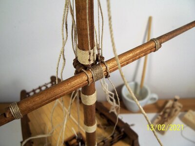
A heartfelt thanks to Dario and all the model ship friends!
As written above, the center ligature needs to be much wider because it needs to support the halyard and parrel cables.
This is a photo of the ligature in its final state. Its width has been increased to 22mm.
.JPG")
See you soon!
Rodolfo.
As written above, the center ligature needs to be much wider because it needs to support the halyard and parrel cables.
This is a photo of the ligature in its final state. Its width has been increased to 22mm.
See you soon!
Rodolfo.
- Joined
- Feb 15, 2021
- Messages
- 97
- Points
- 143
Dear friends
to fasten the yard to the mast it is necessary to build the parrel.
AMATI solved the problem in a very simple manner, with a row of spheres and knots:
This arrangement is historically valid since the "Reliquary of St. Ursula" by Hans Memling, prior to 1489, shows similar solutions:
.JPG")
.JPG")
But it was probably suitable only for small ships (indeed, they do not have the top), since in the "Storie di Sant'Orsola" by Carpaccio (1495) there are large ships with four rows of trucks as well:.JPG")
Our Coca has two rows of trucks:
.png")
.png")
From the pictures, it is not clear how the parrel is arranged between the mast and the yard. In his book, Xavier Pastor proposed some solutions, among them:

.jpg")
In the end, I decided to keep it simple, suitable for the small size of the ship:

Unfortunately, like blocks and deadeyes, commercially available parrels with their trucks and ribs are sold in sachets and in various sizes, but they don't seem suitable for our ship (too small, in my opinion):

 In the second picture, handmade rib and truck.
Next time, we'll build them.
See you later!
Rodolfo
to fasten the yard to the mast it is necessary to build the parrel.
AMATI solved the problem in a very simple manner, with a row of spheres and knots:
This arrangement is historically valid since the "Reliquary of St. Ursula" by Hans Memling, prior to 1489, shows similar solutions:
But it was probably suitable only for small ships (indeed, they do not have the top), since in the "Storie di Sant'Orsola" by Carpaccio (1495) there are large ships with four rows of trucks as well:
Our Coca has two rows of trucks:
From the pictures, it is not clear how the parrel is arranged between the mast and the yard. In his book, Xavier Pastor proposed some solutions, among them:
In the end, I decided to keep it simple, suitable for the small size of the ship:
Unfortunately, like blocks and deadeyes, commercially available parrels with their trucks and ribs are sold in sachets and in various sizes, but they don't seem suitable for our ship (too small, in my opinion):
In the second picture, handmade rib and truck.Next time, we'll build them.
See you later!
Rodolfo
- Joined
- Feb 15, 2021
- Messages
- 97
- Points
- 143
Dear friends welcome aboard again!
I tried to see what commercial parrels looked like. If they had fit well, I probably would have saved myself the trouble. Unfortunately, they are too small, probably will be on a scale of 1:70 or 1:80 if not 1:100, as you can see above in the comparative photo.
Luckily the construction is not difficult: for the ribs, I glued a dozen pieces of lath 5 mm wide and a dozen long to have a margin of correction, shaped and drilled diam. 1.2 mm, then separated by immersion in water:


For the trucks, you can use the ones in the AMATI package but they are only eight and so not enough to make two rows. So I drilled a 5 mm walnut rod then sliced it into many cylinders about 5 mm long; each cylinder is placed on a toothpick inserted into a chuck and worked with a file and sandpaper until it is almost the size of the AMATI ones.


Then they are placed between two walls of sandpaper (one is glued on a discarded kitchen item that I immediately appropriated):


Beware that the last step creates a lot of waste! The walnut spheres tend to break. Perhaps it's better to use another harder type of wood. The white spheres are the AMATI ones. You can see the remarkable uniformity of size. In any case, enough came out for the two rows that I had proposed:

The next step is to build the parrel.
See you soon!
Rodolfo
I tried to see what commercial parrels looked like. If they had fit well, I probably would have saved myself the trouble. Unfortunately, they are too small, probably will be on a scale of 1:70 or 1:80 if not 1:100, as you can see above in the comparative photo.
Luckily the construction is not difficult: for the ribs, I glued a dozen pieces of lath 5 mm wide and a dozen long to have a margin of correction, shaped and drilled diam. 1.2 mm, then separated by immersion in water:
For the trucks, you can use the ones in the AMATI package but they are only eight and so not enough to make two rows. So I drilled a 5 mm walnut rod then sliced it into many cylinders about 5 mm long; each cylinder is placed on a toothpick inserted into a chuck and worked with a file and sandpaper until it is almost the size of the AMATI ones.
Then they are placed between two walls of sandpaper (one is glued on a discarded kitchen item that I immediately appropriated):
Beware that the last step creates a lot of waste! The walnut spheres tend to break. Perhaps it's better to use another harder type of wood. The white spheres are the AMATI ones. You can see the remarkable uniformity of size. In any case, enough came out for the two rows that I had proposed:
The next step is to build the parrel.
See you soon!
Rodolfo
Clever idea with a good result - I am looking forward to see the them rigged in the string
- Joined
- Feb 15, 2021
- Messages
- 97
- Points
- 143
Hi Uwe, here we are!
I liked this arrangement by H. E. Adametz for his Santa Maria:

and I have tried to do this with both a block and a thimble. But the results were not good:


So I decided to get rid of the wooden block/thimble and replace it with a ring made from the rope of the parrel. The extra space allowed me to add a pair of ribs and trucks.


At this point, I realized that the binding in the centre of the yard was too short and the tie of the parrel fell outside it. So I enlarged the central ligature of the yard in this way:.JPG")
The next step will be to fix the yard...
See you soon!
Rodolfo
I liked this arrangement by H. E. Adametz for his Santa Maria:
and I have tried to do this with both a block and a thimble. But the results were not good:
So I decided to get rid of the wooden block/thimble and replace it with a ring made from the rope of the parrel. The extra space allowed me to add a pair of ribs and trucks.
At this point, I realized that the binding in the centre of the yard was too short and the tie of the parrel fell outside it. So I enlarged the central ligature of the yard in this way:
The next step will be to fix the yard...
See you soon!
Rodolfo
Attachments
- Joined
- Feb 15, 2021
- Messages
- 97
- Points
- 143
Dear ship modelers welcome aboard!
I've been thinking about the mainmast lifts for quite a while. The AMATI solution of starting the rigging from a ligature at the top of the upper block was not aesthetically pleasing to me, even when using a self-made block:.JPG")
.JPG")
Since at the time there were also blocks with holes at both ends, I thought of starting the rigging from the blocks themselves, thus maintaining a certain "straightness":


The photos show the situation with the ropes unstretched, as I will eventually lower the yardarm onto the deck. The next step will be the construction of Jakob's ladder...
See you soon,
Rodolfo
I've been thinking about the mainmast lifts for quite a while. The AMATI solution of starting the rigging from a ligature at the top of the upper block was not aesthetically pleasing to me, even when using a self-made block:
Since at the time there were also blocks with holes at both ends, I thought of starting the rigging from the blocks themselves, thus maintaining a certain "straightness":
The photos show the situation with the ropes unstretched, as I will eventually lower the yardarm onto the deck. The next step will be the construction of Jakob's ladder...
See you soon,
Rodolfo
- Joined
- Aug 8, 2019
- Messages
- 5,752
- Points
- 738

Nice work. Rigging of these old ships is a challenge to do, because there is just a little knowledge about how too.
But another possibility could be that the lift starts on the loop of the stay. The blocks are attached to the loop too. Just like how lifts on continental ships where rigged till the early 17th century.
But another possibility could be that the lift starts on the loop of the stay. The blocks are attached to the loop too. Just like how lifts on continental ships where rigged till the early 17th century.
- Joined
- Feb 15, 2021
- Messages
- 97
- Points
- 143
Hi dear friends!
You are right, Stephan; I've seen such a solution, too.
About Jakob's ladder, I made some attempts: this was the first, too weak:.JPG")
This was the second, too wide:
.JPG")
.JPG")
And this is the last attempt which, all things considered, I am quite satisfied with:


Maybe, the optimal choice would have been the second but narrower.
From the bronze bas-relief depicting the sacrifice of Jonah (1514) it is clear that the bottom of the top is closed:
If the bottom is closed, the ladder is outside the top, as in this drawing of H. Winter about its "Santa Maria":
But we also have evidence that the top underneath may have had an opening, like in this one "Schlusselfelder Schiff" from 1503:.JPG")
Our Nao seems to be open or perhaps it has broken at the bottom over the centuries:
After that, I've decided to build Jakob's ladder ending in a hole in the bottom of the top, even if very narrow:
Next step: the standing rigging.
See you later!
Rodolfo
You are right, Stephan; I've seen such a solution, too.
About Jakob's ladder, I made some attempts: this was the first, too weak:
This was the second, too wide:
And this is the last attempt which, all things considered, I am quite satisfied with:
Maybe, the optimal choice would have been the second but narrower.
From the bronze bas-relief depicting the sacrifice of Jonah (1514) it is clear that the bottom of the top is closed:
If the bottom is closed, the ladder is outside the top, as in this drawing of H. Winter about its "Santa Maria":
But we also have evidence that the top underneath may have had an opening, like in this one "Schlusselfelder Schiff" from 1503:
Our Nao seems to be open or perhaps it has broken at the bottom over the centuries:
After that, I've decided to build Jakob's ladder ending in a hole in the bottom of the top, even if very narrow:
Next step: the standing rigging.
See you later!
Rodolfo
Last edited:
- Joined
- Jun 2, 2021
- Messages
- 36
- Points
- 48

WOW ! I have always been intrigued and amazed by these type vessels. I have studied and read all I could find on such ships. Those of Christopher Columbus particularly. And little there be that is absolutely correct. But as you have demonstrated, wood carvings, coins, paintings and of course, other model’s provide those little details. Your approach to this rendering has been most thorough and logical. I have had this kit for some time. You sir have inspired another look over for a future build. Looking forward to more of this most excellent build.
Rick
Rick
- Joined
- Feb 15, 2021
- Messages
- 97
- Points
- 143
Thanks, Rick,
I am very pleased to have been able to contribute to the improvement of this model and I am sure that other modelers will go even beyond, with further discoveries and information. I would also like to thank all those who have expressed their interest in this construction.
At this point we move on to setting the shrouds, starting from the deck with the rings on the bulwark stanchions. If I could start now, I would put rings directly on the deck, always close to the bulwark, or a beam attached to the bulwark with four or five rings and metal bars to support the lower blocks.
But now it's done and, after all, the Nao di Matarò also has their blocks tied to a ring with a cable:


To keep the blocks at a constant distance from the top of the bulwark, I used a screw compass:
.jpg")

At the end of the work, four blocks on each side were placed (instead of three as in the AMATI project):
.JPG")
If someone wishes, more blocks can also be placed, since there is space (Obviously some extra riggings have to be set up beforehand).
The ladder was attached at the bottom to rings and at the top wrapped around the coastal bars and then attached to eyebolts projecting below the top.
In the next post, the upper part of the shrouds.
See you soon!
Rodolfo
I am very pleased to have been able to contribute to the improvement of this model and I am sure that other modelers will go even beyond, with further discoveries and information. I would also like to thank all those who have expressed their interest in this construction.
At this point we move on to setting the shrouds, starting from the deck with the rings on the bulwark stanchions. If I could start now, I would put rings directly on the deck, always close to the bulwark, or a beam attached to the bulwark with four or five rings and metal bars to support the lower blocks.
But now it's done and, after all, the Nao di Matarò also has their blocks tied to a ring with a cable:
To keep the blocks at a constant distance from the top of the bulwark, I used a screw compass:
At the end of the work, four blocks on each side were placed (instead of three as in the AMATI project):
If someone wishes, more blocks can also be placed, since there is space (Obviously some extra riggings have to be set up beforehand).
The ladder was attached at the bottom to rings and at the top wrapped around the coastal bars and then attached to eyebolts projecting below the top.
In the next post, the upper part of the shrouds.
See you soon!
Rodolfo
Last edited: