• Win a Free Custom Engraved Brass Coin!!!
    As a way to introduce our brass coins to the community, we will raffle off a free coin during the month of August. Follow link ABOVE for instructions for entering.

Modelship Dockyard - New Kit [Modelship Dockyard] PoF H.M.S. Enterprize 1774, the 1/48 version!

yes my blandford had a couple not aligned exactly

Just looking at Hanging Knees
L1d Looks like the LOdging Knees D6 C6
L1e Looks like the Hanging knees E3

ABOVE FOR LOWER DECK

Ld2 Looks like the Lodging Knees for GUNDECK D5
I then have =E4 which has numbers not and Ld numberv
Is this for GunDEck

WHAT SIZE ARE CARLINGS on these DEcks Please
THESE JUST ASKING not reall looked
ive then got another E4
Which has an A & B
Are these Quarter DEck
And what is E5 & E3

THanks
JUST SEEN F3 has Carlings for GUN DDECK and 16 Hanging Knees presume they are for same DECK ?
 
Interestingly ALLEN says he would recommend cutting the slots as you FIT them
An alternative that I have used with success is place all the beams exactly where they will go when glued in, then using a template or rule or whatever, mark out the slots for the carlings. It can be easier to make the cuts off the model depending on the tool. I use a slit saw and chisel but whatever you prefer is the way to go. In The Fully Framed Model Volume 1, David Antscherl shows a method that I now use most of the time. Instead of cutting the beam so there is a shelf, just cut an angled slot. This is really easy to do with the beams in place or off the model and easier to size and then set the carling .
Allan

1761992091462.jpeg
 
Last edited:
An alternative that I have used with success is place all the beams exactly where they will go when glued in, then using a template or rule or whatever, mark out the slots for the carlings. It can be easier to make the cuts off the model depending on the tool. I use a slit saw and chisel but whatever you prefer is the way to go. In The Fully Framed Model Volume 1, David Antscherl shows a method that I now use most of the time. Instead of cutting the beam so there is a shelf, just cut an angled slot. This is really easy to do with the beams in place or off the model and easier to szie and then set the carling .
Allan

View attachment 553890


I've also seen this method in Phillip Reed's book 'Building a Miniature Navy Board Model'. It's a method that scales well.
 
Getting the notches cut in the exact right place before the beams are installed is difficult regarding alignment if the beams are not perfectly placed. Many find it better to install the beams, then mark out the notches for the carlings and cut or file a notch so they are properly aligned. Just another way to achieve a perfect result. It is not such a big deal for a cross section model as there are not that many beams and it is pretty much straight line midships, but for a full hull, it can be tricky to have everything lined up.
Allan
Absolutely. Since I am about 1/2 way through lower deck I can assure you several beams are adjusted to fit, especially the fore and aft beams.
Below I am fitting all then marking/filing notches at angle for carlings. Gun deck, I will fully notch to correctly fit carlings AFTER beams are trimmed , dry fit.

Tim
 
Last edited:
An alternative that I have used with success is place all the beams exactly where they will go when glued in, then using a template or rule or whatever, mark out the slots for the carlings. It can be easier to make the cuts off the model depending on the tool. I use a slit saw and chisel but whatever you prefer is the way to go. In The Fully Framed Model Volume 1, David Antscherl shows a method that I now use most of the time. Instead of cutting the beam so there is a shelf, just cut an angled slot. This is really easy to do with the beams in place or off the model and easier to szie and then set the carling .
Allan

View attachment 553890
Actually I have an angled rifler with thin sides than makes fast work for this approach, a bit thin but easy to properly widen with a #11 blade.

Tim
 
An alternative that I have used with success is place all the beams exactly where they will go when glued in, then using a template or rule or whatever, mark out the slots for the carlings. It can be easier to make the cuts off the model depending on the tool. I use a slit saw and chisel but whatever you prefer is the way to go. In The Fully Framed Model Volume 1, David Antscherl shows a method that I now use most of the time. Instead of cutting the beam so there is a shelf, just cut an angled slot. This is really easy to do with the beams in place or off the model and easier to size and then set the carling .
Allan

View attachment 553890
REALLY LEARNING THANKS
So far my slots run to the bottom of the beam But this will look better and easier

I see that ALBAN when building the frames has a set of frames around the gun port and cuts it to size as he goes along
So he cuts say16 b 17 a and b and 18 a
These he cuts to size and then works fore of aft gluing them in assembling and cutting in sets
This would stop the difficult work of cutting them on the frame
MODYFIED TO MAKE SENSE
 
Last edited:
HAWSE PIECES HAVE ARRIVED
Thanks Victor
Finishing off inner planking
Ill build the hawse and no 1 on inner planking
 
VICTOR
Hawse pieces have arrived THANKS
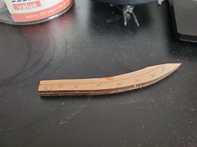
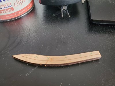
May i suggest on you next model you mark the pieces to cut away with Crosses
My first attempt ruined a piece so needed th replacement - al going ok now
Needs tidying up 7 to add
I notice that X8 is shorter - hopefull this is correct

20251108_121649.jpg

20251108_121655.jpg

20251108_121716.jpg
 
still very frustrated by the TERRIBLE instructions - or lack off
What is needed is more illustrations
Ive cocked up the Hawse AGAIN
THe outer part is fine but there are marking on the inside that suggest that these are left in but because we only get a outer picture its not obvious what happend and how the inner works
Ive trimmed mine of all together and t fits better ~~ the underside of this
1763198659244.png

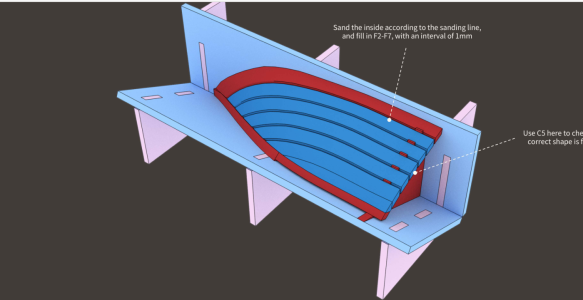
Also the inner planking
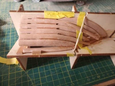
The jig is brilliant but we need some sort of jig to mark where the fore end goes on the bow

1763198611077.png
here at the bow where the it meets the stem
 
still very frustrated by the TERRIBLE instructions - or lack off
What is needed is more illustrations
Ive cocked up the Hawse AGAIN
THe outer part is fine but there are marking on the inside that suggest that these are left in but because we only get a outer picture its not obvious what happend and how the inner works
Ive trimmed mine of all together and t fits better ~~ the underside of this
View attachment 557035

Also the inner planking
The jig is brilliant but we need some sort of jig to mark where the fore end goes on the bow

View attachment 557034
here at the bow where the it meets the stem
Richard, FWIW this is not that hard, you need to visualize the parts and where they will be when finalized, the jig makes it pretty hard to screw up.
The taper lines are just like any other....frames, etc.
The only somewhat tricky part is properly locating the actual cant frame, the end of which locates in the jig hole. It sits proud of hawse as to locate onto frame step, gotta realize, that hole must be there for a reason.
Don't taper exactly to lines so you can finish taper after you pull everything from the jig.
If you've screwed it up it will be far easier to source a piece of wood and fab new ones using the parts frames as templates as opposed to waiting for delivery from China, Your's to take or ignore but the bollards and jig are rather intuitive to build, likely why zero exact direction.

Tim
 
Last edited:
Richard, FWIW this is not that hard, you need to visualize the parts and where they will be when finalized, the jig makes it pretty hard to screw up.
The taper lines are just like any other....frames, etc.
The only somewhat tricky part is properly locating the actual cant frame, the end of which locates in the jig hole. It sits proud of hawse as to locate onto frame step, gotta realize, that hole must be there for a reason.
Don't taper exactly to lines so you

Tim
Cant get the right wood here
But its the back of the Hawse pieces that are the problem All we Need it a picture of what it should look like Cant frames are fine apart from the fact I cut a bit too much Off but they are OK
THe Hawse ends up withe lumps on the back - have you done this yet its where it fittes on tgo X8a INNER which you cant see till its taken off the Jig
Ive cut them off but its not as tidy as i would like

As For the Inner Planking - again the JIG is Brilliant but its where the Fore ends of the planking meet the the Bow
There is no way of knowing exactly where they fit and i guess this is critical to fitting the DEcks
Its not the kit or the Jigs its the exact positioning and a few more photos
I cant show the problem because its fitted AND REALLY WELL
I found that cluing the No 7 Hawse piece to the bow- allowing it to dray and then spreading it to joinn X8a and b Was really Nice
But that Inner edge on No 7 to Bow piece is untidy

IMG_20251116_163630[1].jpg
 
The outer Hawse is great
But the inner is the problem With a photo or illustration it would be easier
I am talking about once the haws is removed from the JIG

Ive fittec it now but not really happy

NEXT

hi trying to find out exactly what frame the Fore Platform begins at and Ends at
I think it between of X2 and Back of 6
Also cant see any Holes for the Masts looks like the foremast is in front of the Foreplatform and the Foremost Wall

Also Beam 13 is the Mid Beam what Frame is this on !!
Just preperation work so i dont make mistakes

Not sure ive read everything but none of these frame numbers seem to be shown anywhere

I also note that JRS has fitted the Inner and Outer TOP PLanking which must make trimming the top of the Hull easier

Incidentally Ive marks the Bottom of the Jig on my drawings and the Top of the JIg - it makes measuring anything above the Jig Much Easier

Posted in mine as well
Cannot tell exactly from your picture but it appears you've closed gap at bottom of hawse pieces, the air gap remains constant right to frames.
If I understand correctly, your ? about inside hawse angle is resolved by simply laying on the jig and tapering hawse until it follows flow of jig....final sanding when fitted.

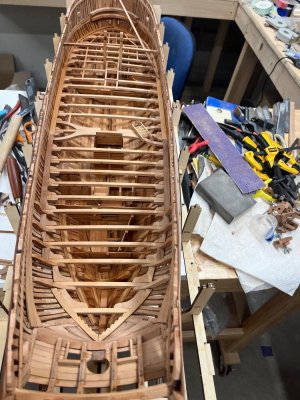
As far as deck beams.....ends butt against sides of keel, On lower deck not super critical since deck beams, lower beam ends, carlings are mostly covered up with waterway planks found, as Victor pointer out, on G4

Beam placements easily ID'd by taking close look at PDF, shows port location and which frame on port to locate ends of platforms.....pretty straight forward.
This method I used and everything measured out.....biggest risk is if wrong, compartments will obstruct knees, hanging knees.....following what I described I had zero interference on any.
Do be aware the sheets for all compartment walls are general, not exact, you need to make "modelers judgement" as to exact height, length to fit under beams and between knees. Their EXACT measurement not critical.....just insure all fit.

P.S. when fitting up inside beams, I'd highly recommend only using 3-4 jigs at a time, mark beams with light pencil, then use medium CA, very lightly......will bond in 10 seconds or so, and follow right from bow to transom.
I can tell you, using this methodology all my deck beams came out dead level the entire deck.
This was a major concern because never used this system but it worked out very well.......never required any measurement from plan with height gauge.
Knees require fair bit of adjustment to follow flow/taper of frames.....be advised.
Tim

IMG_0797.jpeg
 
Last edited:
Cannot tell exactly from your picture but it appears you've closed gap at bottom of hawse pieces, the air gap remains constant right to frames.
If I understand correctly, your ? about inside hawse angle is resolved by simply laying on the jig and tapering hawse until it follows flow of jig....final sanding when fitted.

As far as deck beams.....ends butt against sides of keel, On lower deck not super critical since deck beams, lower beam ends, carlings are mostly covered up with waterway planks found, as Victor pointer out, on G4

Beam placements easily ID'd by taking close look at PDF, shows port location and which frame on port to locate ends of platforms.....pretty straight forward.
This method I used and everything measured out.....biggest risk is if wrong, compartments will obstruct knees, hanging knees.....following what I described I had zero interference on any.
Do be aware the sheets for all compartment walls are general, not exact, you need to make "modelers judgement" as to exact height, length to fit under beams and between knees. Their EXACT measurement not critical.....just insure all fit.

P.S. when fitting up inside beams, I'd highly recommend only using 3-4 jigs at a time, mark beams with light pencil, then use medium CA, very lightly......will bond in 10 seconds or so, and follow right from bow to transom.
I can tell you, using this methodology all my deck beams came out dead level the entire deck.
This was a major concern because never used this system but it worked out very well.......never required any measurement from plan with height gauge.
Knees require fair bit of adjustment to follow flow/taper of frames.....be advised.
Tim

View attachment 558634
What amazing wok
thats great thanks - still a long way off
But all that work on the Hanging and Lodging Knees and they seems to be covered up by the Waterway!!
and if i start at 13 and work for and aft ??
will the well layout will give exact position
 
What amazing wok
thats great thanks - still a long way off
But all that work on the Hanging and Lodging Knees and they seems to be covered up by the Waterway!!
and if i start at 13 and work for and aft ??
will the well layout will give exact position
I did not start there.
I started at #6 carefully using the upper gun deck beam as well, both captured by vertical posts C3 which lwill locate both forward platform as well as lower beam #6 going through the forward platform to frames below.
Be aware, i had to re cut mortice on those posts for the gun deck D3 beam to fit precisely in the mortice and the inner beams for proper spacing between decks. Kit pieces are close but not exact. With mortice adjusted, simple matter of cutting a small filler piece that ends up unseen when all assembled…..lNo big deal.Once that’s done, build forward and aft until you position the well and large beams that position on well top.
Getting #6 proper will get you to well position with lower beams where they should be right to the transom.
Be aware, forward #6 there will be a single beam/ knee combo that will not butt up and leave a small gap, this is your margin for error on beam position for lower deck. Constant review of PDF images reveals all.
After #6 I actually started at structure at the bow and installed beams between #6 and that, then ran beams aft to the well without issue.

Tim
 
Last edited:
I did not start there.
I started at #6 carefully using the upper gun deck beam as well, both captured by vertical posts C3 which lwill locate both forward platform as well as lower beam #6 going through the forward platform to frames below.
Be aware, i had to re cut mortice on those posts for the gun deck D3 beam to fit precisely in the mortice and the inner beams for proper spacing between decks. Kit pieces are close but not exact. With mortice adjusted, simple matter of cutting a small filler piece that ends up unseen when all assembled…..lNo big deal.Once that’s done, build forward and aft until you position the well and large beams that position on well top.
Getting #6 proper will get you to well position with lower beams where they should be right to the transom.
Be aware, forward #6 there will be a single beam/ knee combo that will not butt up and leave a small gap, this is your margin for error on beam position for lower deck. Constant review of PDF images reveals all.
After #6 I actually started at structure at the bow and installed beems between #6 and that, then ran beams aft to the well without issue.

Tim
Sound good - Just building the WEll Needed a break from other things
THANKs
 
Back
Top