And as we cannot see ane difference between the underwater part and the hull side so there is highly hardly a difference in the coulurs - so this massive ship das really a whight surface not a light greyish one.
-

Win a Free Custom Engraved Brass Coin!!!
As a way to introduce our brass coins to the community, we will raffle off a free coin during the month of August. Follow link ABOVE for instructions for entering.
-

PRE-ORDER SHIPS IN SCALE TODAY!
The beloved Ships in Scale Magazine is back and charting a new course for 2026!
Discover new skills, new techniques, and new inspirations in every issue.
NOTE THAT OUR FIRST ISSUE WILL BE JAN/FEB 2026
You are using an out of date browser. It may not display this or other websites correctly.
You should upgrade or use an alternative browser.
You should upgrade or use an alternative browser.
SAINT PHILIPPE 1693 in 1/64 PoB by Iterum
- Thread starter Iterum
- Start date
- Watchers 14
-
- Tags
- ancre saint philippe
Hi Iterum
I bought this book from abebook. Regarding color, I think you can ask G. Delacroix, he is an expert.
Kind Regards
Li
Could you kindly tell me Title and Author of the book?
Last edited:
Thanks a lot, due to your precise information I managed to caught the 95 pages at eBayHi Iterum
Du bois dont on fait les vaisseaux
Service Historique de la Marine - Jean-Pierre Beauvois et Christophe Beyeler eds. - Andrée Corvol - Stéphanie Wicha - Martine Acerra - Jean Boudriot - Magali Theron Kind Regards
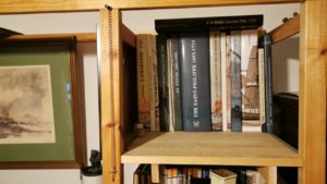
From time to time you need to invest in literature buying a second book for, your library so the first one does not list and falls aside
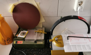
In my opinion, a disk-sander is a must have - better -> I could not be without mine!!! It is the power tool directly close to my normal working deskMy workshop gets a disc sander 250mm is hopefully enough for three Deckers scaled down to 1/64...
View attachment 136273
...I foold my colleauges with the thermos in orange saying it is the original one of my "class mate Otto von Bismarck"and noone figured out the lapsus in the "signature"
Is it the bigger Proxxon? (this one I also use usually)
Yes it is the 250 diameter I thought the small would be to smallI have got the land parts as the keel ect.In my opinion, a disk-sander is a must have - better -> I could not be without mine!!! It is the power tool directly close to my normal working desk
Is it the bigger Proxxon? (this one I also use usually)
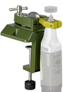
I was really happy to get the unopened but old UHZ today, too.
So I can build a drum drill for the concave parts (of the bulkheads in particular) .
Are here any plans for a table with on opening for the drum sander?
Edit
My 1st sketch of an "idea":
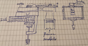
A box with the hole for the sanding drum and pressed on the work bench.
Last edited:
One suggestion, due to the fact, that I know the sanding work with my drum-sander.Yes it is the 250 diameter I thought the small would be to smallI have got the land parts as the keel ect.
View attachment 136295
I was really happy to get the unopened but old UHZ today, too.
So I can build a drum drill for the concave parts (of the bulkheads in particular) .
Are here any plans for a table with on opening for the drum sander?
Edit
My 1st sketch of an "idea":
View attachment 136324
A box with the hole for the sanding drum and pressed on the work bench.
I would use only the 230 Volt version of the Proxxon drills and not the 12Volt versions - you will see, that the drill will run a longer time, maybe partly 30 minutes or so.......so you need a tool which can be switched on for a longer time, without getting hot etc.....
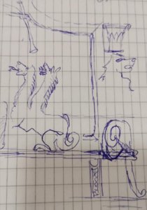
Here my scetch due to understand the figuration at all here
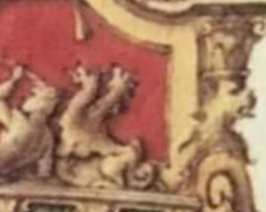
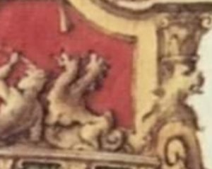
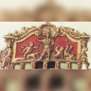
a two-headed dog of the couronnament of TONNANT 1693 in the very right side of the couronnament.
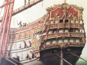
(I want to do the following steps as I am on travel and am only able to think research and scetch in my block.)
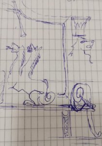
I do absolutely know that all the heights are not right but I was able to catch the idea of this part of the couronnament I hope. Now I have to figure out what fairy tale animal this is - for a Cerberus there is a missing head and throat. (The laying down man is at the left something I will take my interest to later.) Now I have to figure out about the column's head (what is the right word?) on this monster's head. I do remember something like this as a pattern seen in a book about Greek(?) building's decoration...
At home I will deal with the couronnament frame as a copy from the SP-plans first on frostpaper than enlarging it in 2/1 or 4/1 in the Copyshop. So I will earn the "theater of action for my left eye sight" and then add the figures reliefs on frostpaper "over" it.
At the moment I try to get some idea what figures I do have to deal with at all in particular. It is real fun to research and reconfigure te couronnament even in this rough status of scetches. This is a part of the job I really like to do - reconstructing something.

a two-headed dog of the couronnament of TONNANT 1693 in the very right side of the couronnament.

(I want to do the following steps as I am on travel and am only able to think research and scetch in my block.)

I do absolutely know that all the heights are not right but I was able to catch the idea of this part of the couronnament I hope. Now I have to figure out what fairy tale animal this is - for a Cerberus there is a missing head and throat. (The laying down man is at the left something I will take my interest to later.) Now I have to figure out about the column's head (what is the right word?) on this monster's head. I do remember something like this as a pattern seen in a book about Greek(?) building's decoration...
At home I will deal with the couronnament frame as a copy from the SP-plans first on frostpaper than enlarging it in 2/1 or 4/1 in the Copyshop. So I will earn the "theater of action for my left eye sight"
At the moment I try to get some idea what figures I do have to deal with at all in particular. It is real fun to research and reconfigure te couronnament even in this rough status of scetches. This is a part of the job I really like to do - reconstructing something.
Last edited:
I am so stupid old and my brain is so unreliable!

I told you the formers would stand rectangular to the rectangular line, didn't I?
BUT LOOKING AT THIS DRAWING:
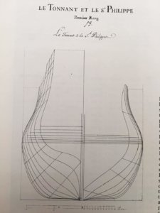
We know that the body plan was drawn with the keel 90° to the viewer:
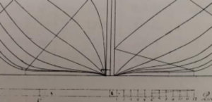
So it is completely and cristal clear that the formers have to stand rectangular to the keel not to the L.F./CWL. So I have to redraw the frostpaper with all the positions of the grooves for the bulkheads.
Stupid modellers have to do their work twice...


I told you the formers would stand rectangular to the rectangular line, didn't I?
BUT LOOKING AT THIS DRAWING:

We know that the body plan was drawn with the keel 90° to the viewer:

So it is completely and cristal clear that the formers have to stand rectangular to the keel not to the L.F./CWL. So I have to redraw the frostpaper with all the positions of the grooves for the bulkheads.
Stupid modellers have to do their work twice...

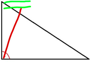
But where to place the start of the grooves over the keel? (Let's say the keel has an angle of 5° to the L.F.) so we have
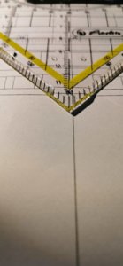
to turn the grooves with 5°? Adding the error of 0,9°?
Where do I put the axle of turning?
So do I just
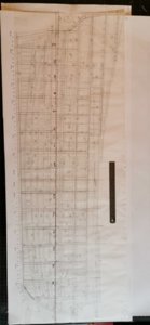
a) fix them in the L.F. the formers do move towards the STEM post
b) in the corrected rectangular line (German Purple) the formers will shift less to the stem post
c) swing them around their crossing to the keel/hull meeting point the bulkheads tops will move to the stern post
If I would know CAD I would easily be able to show you that the result is very different. But when I do it will I not do get a compressed hull in hight?
@G. DELACROIX
Or do I have to remember the error of 0,9° and math it into the correct form's lines 5° + 0.9° =5,9° and swing the former's lines by this figure around their point a, b c or somewhere between? Do you have any idea (without changing our models into branders)???
Here the rectangularity to the German Purple line is evident:
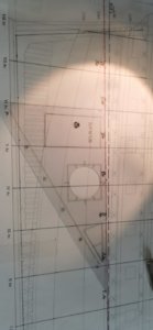
So here the formers lay rectangular to this line.
Thank you very much.

to turn the grooves with 5°? Adding the error of 0,9°?
Where do I put the axle of turning?
So do I just

a) fix them in the L.F. the formers do move towards the STEM post
b) in the corrected rectangular line (German Purple) the formers will shift less to the stem post
c) swing them around their crossing to the keel/hull meeting point the bulkheads tops will move to the stern post
If I would know CAD I would easily be able to show you that the result is very different. But when I do it will I not do get a compressed hull in hight?
@G. DELACROIX
Or do I have to remember the error of 0,9° and math it into the correct form's lines 5° + 0.9° =5,9° and swing the former's lines by this figure around their point a, b c or somewhere between? Do you have any idea (without changing our models into branders)???
Here the rectangularity to the German Purple line is evident:

So here the formers lay rectangular to this line.
Thank you very much.
Last edited:
not very much happend today! - only two big pacels arrived. So not very much to see happend today I have to rebuild the workshop again. I do need a place to keep the buildingboard with enough room to measure everything precisely.
And I want to place the keel parallel to the board so I could errect the bulkheads rectangular to keel and board. Is this a good idea?
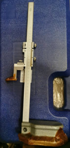
What do I need more?
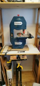
with the sawdust inside to make totally obvious to some greenhorn liks me it is a preowned saw. {The RR kit is from my plastic time of my life.}
And I want to place the keel parallel to the board so I could errect the bulkheads rectangular to keel and board. Is this a good idea?

What do I need more?

with the sawdust inside to make totally obvious to some greenhorn liks me it is a preowned saw. {The RR kit is from my plastic time of my life.}
Last edited:
I bought a formica board for the drawing work of 600x1200x16mm - so I am able to work on a real leveled ground. Also it looked like the pictures were in particular made for our Australian friends  - no the keel up method is shown here.
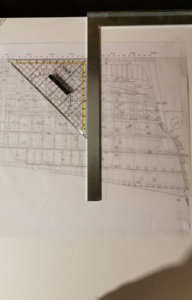
I pinned the copy of plate N°16 "Longitudinal Section With Planking Removed" on the board the inner rabbet-line 100mm from the boards side edge so I could errect the formers in the keel rectangular and all a parallel line fore the building board's surface, so keel and building board are perfectly parallel. I do have to remember the grooves for the bulkheads are from the keel to the mid of the 6mm center board.
So the centerboards as the bulkheads do need posts the keep them in position and the try square will check the situation in the right hight.
Next important solution is to create a line in every bulkhead that corresponds precisely to the master line on the center boarb by this the adjustment of the bulkheads due to hight is checked - the rectangularity to the centerboard is secured by wooden rectangular posts the will aline with the groove.
So the rectangularity is proofed by
1. the lines on centerboards and bulkheads
2. the paralarity of baseboard and keel
3. the rectangular posts aside the grooves lying aline with the formers layer
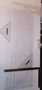
so all the three dimensions are rectangular (only the fourth got wrong it is 03:15a.m. I do need very much more time due to my bad eyesight adjusting the plan on the board and adding the frostpaper layers over it.)
Let's assimilate to our materials wood is workring allways very slowly but it can burst the most solid rock you can think about...
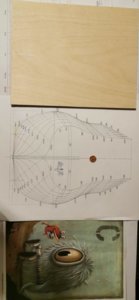
I do have to remember to place the centerboard and bulkhead line exactly on the same distance from the inner rabbet!
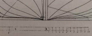
So the inner rabbet must be the place where the former in the bodyplan is errected. (Some bitter information - if you follow the formers line leaving the armof the try square and adding more and more distance you may get an idea how wrong this plan is and how flat your hull is going to be compared to a rectangular placed set of formers.)
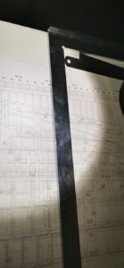
Due to this the inner rabbet
ist the place to start the re-drawing of the formers.
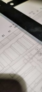
But this will be a hard road to travel* you can see where Lemineur's former is going to run to...
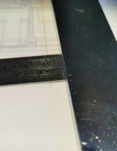
At former Ar.V we get a deviation of 5,75mm - and I do build the smallest model in our "SAINT PHILIPPE trio"!
So if you do not redo the plan due to this the hole hull ist too low and by this in the same moment looking too breadth, too. And your are going to crush your skull by wandering over the decks.
This for now
This from Berlin
This from me
______
*This idiom I learned by music:

I pinned the copy of plate N°16 "Longitudinal Section With Planking Removed" on the board the inner rabbet-line 100mm from the boards side edge so I could errect the formers in the keel rectangular and all a parallel line fore the building board's surface, so keel and building board are perfectly parallel. I do have to remember the grooves for the bulkheads are from the keel to the mid of the 6mm center board.
So the centerboards as the bulkheads do need posts the keep them in position and the try square will check the situation in the right hight.
Next important solution is to create a line in every bulkhead that corresponds precisely to the master line on the center boarb by this the adjustment of the bulkheads due to hight is checked - the rectangularity to the centerboard is secured by wooden rectangular posts the will aline with the groove.
So the rectangularity is proofed by
1. the lines on centerboards and bulkheads
2. the paralarity of baseboard and keel
3. the rectangular posts aside the grooves lying aline with the formers layer

so all the three dimensions are rectangular (only the fourth got wrong it is 03:15a.m. I do need very much more time due to my bad eyesight adjusting the plan on the board and adding the frostpaper layers over it.)
Let's assimilate to our materials wood is workring allways very slowly but it can burst the most solid rock you can think about...

I do have to remember to place the centerboard and bulkhead line exactly on the same distance from the inner rabbet!

So the inner rabbet must be the place where the former in the bodyplan is errected. (Some bitter information - if you follow the formers line leaving the armof the try square and adding more and more distance you may get an idea how wrong this plan is and how flat your hull is going to be compared to a rectangular placed set of formers.)

Due to this the inner rabbet
ist the place to start the re-drawing of the formers.

But this will be a hard road to travel* you can see where Lemineur's former is going to run to...

At former Ar.V we get a deviation of 5,75mm - and I do build the smallest model in our "SAINT PHILIPPE trio"!
So if you do not redo the plan due to this the hole hull ist too low and by this in the same moment looking too breadth, too. And your are going to crush your skull by wandering over the decks.

This for now
This from Berlin
This from me
______
*This idiom I learned by music:
Last edited:
Sorry. In German, because my english.... 
Also wenn ich mir das so ansehe glaube ich nicht, dass da ein Fehler ist. Lemenieur hat das bewusst so gemacht und sich auch was dabei gedacht. Ich würde mich auch von der "Theorie" verabschieden, dass die Spanten normal (90 Grad) auf dem Kiel stehen. Das mag in dem einen oder anderen Idealfall so sein. Aber ob die Praxis damals wirklich genau so war ? Der Kiel stand ja auf einer Rampe unter einem gewissen Winkel beim Bau. Wenn da die Spanten lotgerecht aufgesetzt wurden hast Du schon deinen Versatz im Winkel. Ich würde den Plan genau so leben wie er gezeichnet ist, es sei denn er enthält wirkliche geometrische Fehler.
Der Aufbau ist total leicht in meiner ahnungslosen Phantasie. Deine Scherbretter bekommen einen leichten Versatz in der X Achse, dadurch stehen die Spanten schief.
Du musst nur schauen wie Du den MikroGap unten am Kiel und am Kielschwein in den Griff bekommst. Aber 1 Grad auf die Wandstärke der Spanten.....
Also gilt die Formel "nix * nix = immer noch nix". Das ist wirklich zu vernachlässigen bei einem Grad.
Eines muss dir klar sein. Du kannst nicht einfach Lemenieurs Spantenzeichnungen nehmen und die 1 Grad kippen.
Du veränderst dadurch die Geometrie des Rumpfes !!!! Wenn Du Dich entscheidest Die Spanten 90 Grad auf den Kiel zu setzten musst Du alle Spantenzeichnungen mit Zuhilfenahme des Wasserlinienplans neu herauszeichnen !!!
@Uwek haben wir nicht irgendwie Zugriff auf Jean-Claude ? Das wäre schön wenn der sich mal zu den Problemen oder Fragen äussert. Würde den betroffenen Modellbauern helfen und würde auch dem Ansehen des Plansatzes gut tun.
Last edited:
(...)
@Uwek haben wir nicht irgendwie Zugriff auf Jean-Claude ? Das wäre schön wenn der sich mal zu den Problemen oder Fragen äussert. Würde den betroffenen Modellbauern helfen und würde auch dem Ansehen des Plansatzes gut tun.
I think this is the best question I do really do think so. That would be great to vanish this kind of discussions. And we will kow if this set of given points by a 89,1° bodyplan meeting the deckslines are stringently used throughout the hole plan.
Dear Oliver,
the formers due to
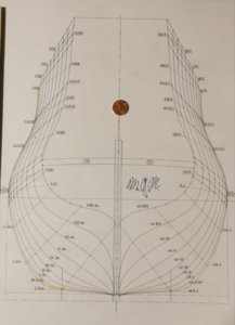
this mirrowed bodyplan from the monographie
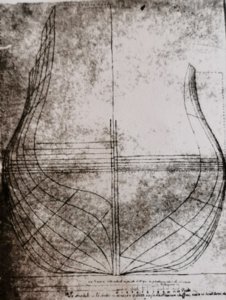
taken from this original
have to be been errected perpendicular to the keel (as the L.F. is shown as a bent line in the monigraphy's bodyplan) .
Sorry to say this but the very fundamental layer of any plan are rectangular lines. If this isn't done right the hole ship's planset is nonsensical. I think the formers would have to stay rectangular to the keel - you cannot saw grooves in your centerboard at an angel of 89,1°. { Certainly you could do it but it wouldn't make sence due to an unrectanglar try edge [Anschlagwinkel] you would have to construct.}
I think I will look and testify if the hole plan is based on the 89,1° than the bodyplan is right. Because of the discrepancies of the mentioned 5-3/4mm the hight of the poop deck will rise 0,3mm what is nearly the half of the decksplanking thickness. (our friends of Pythagoras will kindly give a precise numer to me?) on the original the difference would be 192mm. And please dont forget that our friend Nigel on his island has to deal with a diff of nearly half a millimeter at his beautiful scale of 1/36.
Due to all this I do think the formers were errected yes navalhistoricaly you are on the right side but mit nearly a full degree.
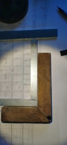
This as my 100 yeaer old wooden try edge I have got is quite precise...
Last edited:


