I love the timber you are using Nigel.
-

Win a Free Custom Engraved Brass Coin!!!
As a way to introduce our brass coins to the community, we will raffle off a free coin during the month of August. Follow link ABOVE for instructions for entering.
-

PRE-ORDER SHIPS IN SCALE TODAY!
The beloved Ships in Scale Magazine is back and charting a new course for 2026!
Discover new skills, new techniques, and new inspirations in every issue.
NOTE THAT OUR FIRST ISSUE WILL BE JAN/FEB 2026
You are using an out of date browser. It may not display this or other websites correctly.
You should upgrade or use an alternative browser.
You should upgrade or use an alternative browser.
Saint-Philippe 1693-POF to the Monograph by Jean-Claude Lemineur by NMBrook-1/36
- Thread starter NMBROOK
- Start date
- Watchers 81
-
- Tags
- ancre saint-philippe 1693
NIGEL THIS IS YOUR FIRST SCRATCH BUILD, THIS IS GODS GIFT TO YOU, SOME HAVE IT ALL YOU DO. GOD BLESS STAY SAFE. Don
L'Ambiteaux!Thankyou Gents
Yes this is my first POF build after years bashing kits to death.There has been nothing that really inspired me in Ancre's catalogue previously apart from L'Ambiteaux but that was long out of print.Ironically that has been reprinted around the same time as this Monograph was released.
Kind Regards
Nigel
The two biggest ships - you like these "more than 100 guns"-vessels, or?
Planset review - THE THREE-DECKER of the Chevalier de TOURVILLE - LE TROIS-PONTS du Chevalier de TOURVILLE - L’AMBITIEUX - 1680" by Jean Boudriot
Planset Review: THE THREE-DECKER of the Chevalier de TOURVILLE LE TROIS-PONTS du Chevalier de TOURVILLE L’AMBITIEUX 1680 by Jean Boudriot Two volume set available in English, French or Italian language directly from ancre...
shipsofscale.com
The framing of the L'Ambiteaux is definitely "easier" to make ..... if something like this can be "easy" .....
Thankyou
Brian,yes the Pear is lovely,it is also a joy to work with
Maarten,I agree these vessels look better naked,at least on their lower half
Uwe,mmm never say never but I have my work full for the next twenty years with this and other projects,ask me then Yes I do I have a love of 17th Century Three Deckers but they are alot of work.I honestly don't think I could have picked a vessel with more complex framing.Even the English style with Cant and Shifted frames seems less work compared to this
Don,thankyou,strictly speak,my Sovereign of the Seas ended up a scratchbuild as nothing of the kit remains but this is my first go at POF
Kind Regards
Nigel
Brian,yes the Pear is lovely,it is also a joy to work with
Maarten,I agree these vessels look better naked,at least on their lower half
Uwe,mmm never say never but I have my work full for the next twenty years with this and other projects,ask me then
 Yes I do I have a love of 17th Century Three Deckers but they are alot of work.I honestly don't think I could have picked a vessel with more complex framing.Even the English style with Cant and Shifted frames seems less work compared to this
Don,thankyou,strictly speak,my Sovereign of the Seas ended up a scratchbuild as nothing of the kit remains but this is my first go at POF
Kind Regards
Nigel
- Joined
- Oct 23, 2018
- Messages
- 886
- Points
- 403

Sovereign of the Seas ended up a scratchbuild as nothing of the kit remains but this is my first go at POF
Do you have a line drawing of the hull? The new book of McKay is nice, but I don't agree with his lines. The stern looks awful.
Hi Christian
Unfortuneatly I don't.I blocked the Deagostini carcass out in lime blocks and then carved it to suit what I believed to be correct at the stern.
I agree with you,I do not know where McKay got the very deep transom from.He took cues from the Tudor Carrack but the Mary Rose's transom was not that deep
Kind Regards
Nigel
- Joined
- Oct 23, 2018
- Messages
- 886
- Points
- 403

I am happy, that I have to run the Triton-marathon before I can think for another project. But "de gouden duivel" is a really fascinating project for the future
Christian all I will say is buy all the literature first before you make any dust,McKay chose not to use the two most important books for his research for whatever reason.Those of Busmann and Sephton.
Kind Regards
Nigel
Kind Regards
Nigel
That was exactly my question also, in respect to proper functioning of the rudder this deep transom doesn't look right. I am currently reading his book but haven't found yet where this stern design from him is coming from.Hi Christian
Unfortuneatly I don't.I blocked the Deagostini carcass out in lime blocks and then carved it to suit what I believed to be correct at the stern.
I agree with you,I do not know where McKay got the very deep transom from.He took cues from the Tudor Carrack but the Mary Rose's transom was not that deep
Kind Regards
Nigel
I have now commenced work on the next batch of frames.I have covered this in detail before so I have no intention of repeating the process in my log.
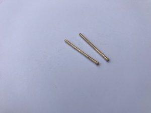
However,I have got a little side job going whilst waiting for glue to dry.I am manufacturing the bolts that would go through the keel into the floor timbers.There is no false keel according to the drawings so these would be visible underneath.I actually want to fit these for structural reasons but I may as well make them look authentic.
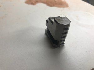
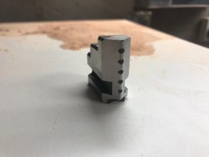
The process would involve turning 1.5mm Square brass bar to 1.4mm diameter leaving a square head at one end.So much is based on the length of available drills,much less than 1.5mm and it will not get the depth to go well into the floor timbers.The intention is that these are epoxied in place.The square head is only 1mm high so this will be tapped flush.
With the independent four Jaw chuck in my new lathe I faced an immediate issue.The chuck only closed up to about 4mm square.I removed the chuck jaws and ground bigger chamfers on each one to enable the chuck to close up enough to grip the 1.5mm square bar.This was a slow job to keep the heat in the jaws down and took several hours.
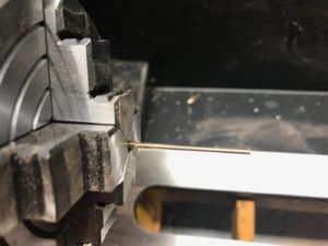
With the chuck sorted,turning was a simple affair but only machining 5mm or so of the diameter at a time and then moving the workpiece further out of the chuck in stages.No other method could have prevented the soft brass from bending out of control due to the small diameter.Once the diameter was turned,the piece was parted off leaving the square head intact.
Kind Regards
Nigel


Now a little deviation,firstly as I wanted to "prove" the drawings and fancied a rest from hull frames as such.
The Beakhead bulkhead is quite complex in both it's profile and the fact it spans two decks.The drawings are limited in this area as to the framing so it is very much a case of working things out oneself.This assembly will be built entirely of African Red Paduak as it was painted red throughout on the original.
The weird thing is it's base does not actually touch the second gun deck.The beam at it's base actually floats 7mm above creating a void under the Beak deck.I did question myself on this interpretation but low and behold Amalio posted some pics of his Spanish 74 only this morning on Facebook,I know the timeframe and Nationality are different,but it is exactly the same.A gap is present.
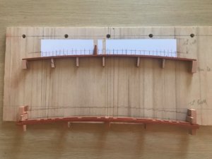
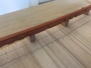
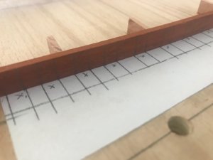
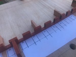
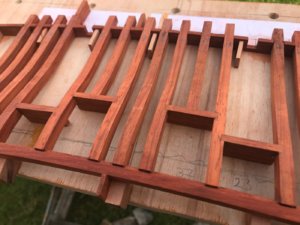
On to the construction aspect,I knew that this would be easier to build off the vessel.I constructed a crude jig to assemble the framework.In the pictures are the main beam,this is sawn with the cambered profile in it.The small square notches are to take the base of the uprights.The 4 large gaps are where the top of the beam forms the cill for two door and two gunports.The continual rebate on the corner is to take the ends of the Beak deck planking.
The strip at the top is the caprail for the planking.This has been marked out for the notches for the uprights that run through to form the railing.This is a straight strip bent to conform to the Camber.The piece should hold it's shape once assembled.
Both Beam and rail have been cut overlength to allow them to be spot glued into the jig.The five holes are so the jig can be bolted to the mill table(MF70) for cutting the notches in the caprail
Kind Regards
Nigel


Last edited:
Hello Nigel,
the colour of that African red paduack is spectacular, but its known for not holding its colour after varnishing. I had a problem with using red heart timber. It looked great in its natural finish, but turned a disappointing dull brown after varnishing with oil based satin poly.
Just making an observation buddy.
Hi Brian
It keeps it's red colour better if you use Shellac,regular varnish kills the colour as I found out with the Rider frame
Kind Regards
Nigel
It keeps it's red colour better if you use Shellac,regular varnish kills the colour as I found out with the Rider frame
Kind Regards
Nigel
You could also leave it natural, and apply wax to seal it. cheers.
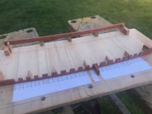
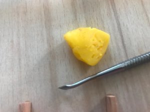
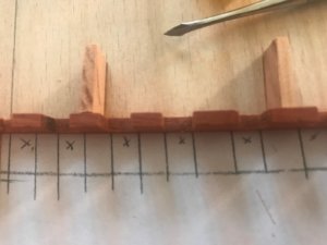
I have cut all the notches out using the Proxxon mill.It was slow going as the Padauk is hard and splintery meaning small cuts at a time.I then drilled 0.5mm holes on the caprail central to the base of the notches.These are for the "nailing" when the unit is removed from the jig.These are easy to eyeball for position from this side rather than trying to line up with the centre of the uprights from the other side later.I then carefully filled the top of the holes with moulding wax.This will stop the epoxy from filling these holes back up when I glue the uprights in
Kind Regards
Nigel
Kind Regards
Nigel


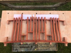
Next step was to cut 17 uprights.I photocopied a tracing taken from the plans 17 times and pasted onto some 6mm Paduak sheet.These were cut out on the bandsaw close to the line.The only area I dressed up with sanding was the flat area that sits in the caprail notch.These will be faired once assembled just like you would with the main hull framing.
I have milled the notches in the uprights for the other timbers before assembly.The cills and heads of the doors were left oversize to give me a larger area to square up.What you can now see is two doorways either side of centreline and two lower gunports.
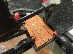
The last picture is a trail piece of planking to see how my proposed plan for Caulking looks.Caulking in 1/36 is SO much more than a simple pencil line and in my opinion I would have to use very thick black paper to achieve something close to the width in reality.The caulking on Victory's deck is something between 15mm to 20mm wide from memory so I am experimenting using 0.5mm thick black Marquetry veneer to see what it looks like.If it doesn't look too much then I can buy this in various widths e.g. 2.4mm,just slightly wider than my planking thickness in this case.This will give me a better structural joint rather than introducing very thick paper/card.
Kind Regards
Nigel


Last edited:
Hello Nigel great progress you do - thanks for sharing with us....
I'm not sure how I missed this build log, but I did! I'm here now. Fantastic work, Nigel. Just beautiful!
Welcome Dave and Thankyou
Kind Regards
Nigel
Kind Regards
Nigel


