Wow, that's nice looking timber you are using Nigel.
-

Win a Free Custom Engraved Brass Coin!!!
As a way to introduce our brass coins to the community, we will raffle off a free coin during the month of August. Follow link ABOVE for instructions for entering.
-

PRE-ORDER SHIPS IN SCALE TODAY!
The beloved Ships in Scale Magazine is back and charting a new course for 2026!
Discover new skills, new techniques, and new inspirations in every issue.
NOTE THAT OUR FIRST ISSUE WILL BE JAN/FEB 2026
You are using an out of date browser. It may not display this or other websites correctly.
You should upgrade or use an alternative browser.
You should upgrade or use an alternative browser.
Saint-Philippe 1693-POF to the Monograph by Jean-Claude Lemineur by NMBrook-1/36
- Thread starter NMBROOK
- Start date
- Watchers 81
-
- Tags
- ancre saint-philippe 1693
Hi Brian
Contraversially I am planning on staining it.This will bring out the depth of the timber but at the same time blend the different tones.To try and keep the same shade of Pear throughout on a build this size would be next to impossible.I will have to stain components before assembly.This is the only to ensure no visible glue marks.
The Pear will appear darker than if just covered with Tung Oil(which I will apply after assembly).This should provide a good contrast for the Castello boxwood of the carvings.Obviously the boxwood will not be stained just oiled.Janos will criticise my choice of Castello over English box but I just can't buy it in big enough chunks for this build.
I have found an interesting thread on La Francois in 1/18 scale,slightly bigger than my model will be,but it gives a good insight into the issues of POF in big scales.The author comments in the instability of the frames in this scale and issues with timber movement.Looks like I will be building mine upside down.
Here is the link,google translator helps http://forum.modelsworld.ru/topic13984.html
Kind Regards
Nigel
Hi All
Today I have cut the 'thick' sides of the frames back to the twentieth bulkhead.I am now starting at bulkhead one and working back tracing parts.I had left these first bulkheads until now.I have had to spend a bit of time getting my head around the geometry and how they mate with the keel.Something didn't look right and now I have sussed it which brings me to post about an error on the drawings.
The first picture shows the top section of frame 2.Note the solid line with the arrow.
The second pic shows the complete absence of that line on the section of frame 1 which is the outside back edge of the upper futtock.
The third pic shows my conservative educated guess of where this falls.I have added more material than is necessary to the upper futtock.This will be sanded down to a true profile when the hull is faired on the outside.
This is the second error I have spotted so far.The first being some lines on the floor timbers which made the scarphs look they curve up on the outsides.This is wrong,the scarphs are horizontal and are shown correctly in the detailed cross sections of the interior.
Kind Regards
Nigel
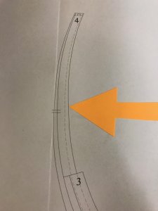
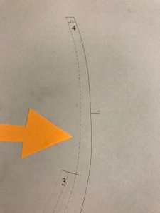
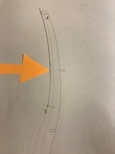


Hello Nigel,I know what you are trying to do ,you want finish the build before the move Lol 

Hi Zolly


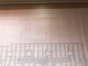
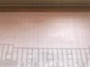
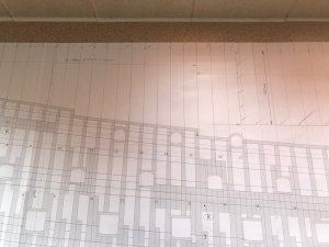
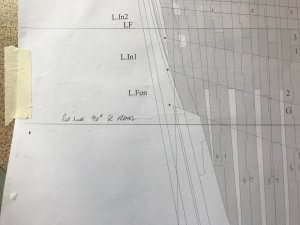
Firstly to correct an assumption made on my behalf.I have started to plan how I am going to build a jig for this monster.Starting to do some setting out on the framing plan,I have discovered the frames are not square to the waterline as I thought but are not square to anything!I firstly drew a reference line perpendicular to the frames full length of the hull to work from.It's position was not important,I just needed a point of reference.
Having decided to adopt a similar approach to Harold Hahn,I worked out where my baseboard is going to be.I have decided to have two levels to reduce the lengths of the frame extensions.Because of the shear on the top of the hull,they would be getting rather silly if I just worked from one level.This position of the baseboard can now be drawn on each frame elevation and the corresponding frame extensions.
I mentioned earlier that the text part of the monograph mentions the middle of the keel was built with a 200mm downward bow on the original vessel to allow for hogging.However on the plan this is straight.I wonder if this bow fell out once the vessel was in water and ballasted?Needless to say,I am working to the drawing.
Finally some pics showing where my baseboard will be(the shaded part) and the reference line.Awkward to photograph the drawing as it is so BIG.
Kind Regards
Nigel


- Joined
- Feb 18, 2019
- Messages
- 717
- Points
- 353

Hello,
First I must say that I do not have the monograph for the ship and I am certainly not an expert on the subject.....
But I do have and am very familiar with the full monograph for the "François", of the same period: although it is a smaller rank vessel built in 1683. The framing is likely to be very similar in some aspects: one of which would be the framing design or practice.
So a few points:
1) As the ship is not built with sistered framing (2 equal thickness full frames assembled together to make 1 complete frame creating a empty space between complete frames), but as there is an interval (empty space) between parts of a frame but practically no empty space between incomplete raised frames, frame built is "steps" or parts of varying thicknesses, it is normal that if you draw a perpendicular line from the foot of the frame (at the keel) the head (at the waist) the line in not going to be square (90 degree angle). This is due to the fact that each section making the height of the frame is of different thickness: basically tapered at the top.
This is especially more pronounced at the stern and the bow where the frames do not have the "square to the keel floor timber" as the base resting on a flat keel surface.. On all the frames between the rising-wood and the foot of the stem, the vertical line creating by the faces of the floor-timber should be perpendicular to the straight line drawn between stern and stem when not taking into account the bow of the keel.
2) building base: given the height of your ship at the stern, it may be a good idea to put together a building base "framing jig" on 2 levels: but is not essential. You can have one lower level "jig" following either the actual waterline or the 1st deck line and one level higher (partial board / jig) towards the stern at say the third deck line. Another way of picking the height for the building base "framing jig" is to use 1 or 2 of the water line found on your plate showing the horizontal line drawing (likely to be plate 2 of the plan set). Although these lines are more difficult to use as they are not physical or concrete lines on any ship in order to be used as a reference. They are just imaginary lines used in determining the shape of the hull
3) Bow of the keel: If that is the case, I would check the plan again as on François the keel has the same feature and it is clearly shown on the plan. The bow of the keel on François is equal to a difference of 1 full height of the keel at the centre between the sternpost and the base of the stem. The centre point of the keel being down by its full height.
G.
Last edited:
- Joined
- Feb 18, 2019
- Messages
- 717
- Points
- 353

This is especially more pronounced at the stern and the bow where the frames do not have the "square to the keel floor timber" as the base resting on a flat keel surface.. On all the frames between the rising-wood and the foot of the stem, the vertical line creating by the faces of the floor-timber should be perpendicular to the straight line drawn between stern and stem when not taking into account the bow of the keel.
Just to clarify, this imaginary straight line would show the top bottom edge of the keel at the foot of the sternpost and the foot of the stem higher than the centre of the bottom face of the keel: that is if you drew an horizontal line at the lower face of the centrepoint of the keel at its lowest point. You may have that shown on the framing plan shown on one of the first plates in your monograph.
Last edited:
- Joined
- Feb 18, 2019
- Messages
- 717
- Points
- 353

As far as the bow of the keel is concerned, I would think that this feature shows up in the plate showing your framing plan.
Can you please post an image showing the area of the keel and sternpost or keel and foot of the stem to verify. I would be surprised if that was the case (bowing not represented in the plan) unless there is a mention somewhere in the monograph explaining why the decision was made by the author to bypass that feature. Those kinds of details would have been part of building regulations / establishments at the time.
On a side note, the representation of the ship``François" and the St Philippe were both designed by François Coulomb 10 years apart.
"François" being the name attributed to the ship by the author of his monograph, is does represent the building practice of the time as the ship's building descriptions are based on François Coulomb manuscript (containing text, drawings and tables) written in 1683 and updated in later years. Monograph authors may have to make difficult but educated decisions about the interpretations of texts written and design drawings of the era: these may contain conflicting descriptions, especially when there are several copies or version of recorded and updated documentation archived in different places........ as was the case for a few features of ``François". It is all about very serious and often complicated research by knowledgeable authors.
I know this is not a popular ship to build but I do not remember reading anything about it anywhere. But I could of course be wrong.
Nothing to do with the keel but scratch building this type of ship according to real representation at the time is not widespread with modelers because of the more complicated framing style and structure as well as the amount and extent of the decoration / carving.
Thank you.
G
Last edited:
Hi Giles
Very interesting posts.Saint Philippe was built to the 1693 establishment and does differ to Francois.The framing is sistered apart from the floor timbers and is also mortised together.
Yes the frames are tapered but I have worked from the centreline to get a true square reference.
I will go back over the text re the keel bow.The framing plan does show a straight keel.I have checked it with a long length of aluminium angle.200mm should equate to 6mm in 1/36
The jig will be on two levels but I am building the hull upside down with framing extended to reach the building board.I feel this will be more accurate and secure given the huge size of the hull.
King Regards
Nigel
Nigel,
Just became aware of your planned journey into the abbyss of scratch building... I am sure with your precisity and attention to details Le Francois will be a beautiful model!
I am not criticising your choice of Costelo for the carvings at all. This is the second best material for carvings and has more than one advantages above the European Boxwood. If coming from a good source its colour and texture is much more consistent, and, which is a huge advantage, it is available in much bigger sizes than the European one. This latter can have a very pleasing straw-yellow colour but only in very much selected pieces and its colour has a bigger variety even in good pieces, not talking about the knottyness and the grey colour spots. These are some of the difficulties I am facing while making the carvings for my Sovereign at the moment. European Boxwood is harder and behaves better during carving - but only if we are lucky to find consistent, good quality pieces.
Ivan Trtanj is in a very rare and lucky situation, having received a tree-size European Boxwood a few years ago, which provides material for his beautiful carvings even today. This tree had a 500 years life span and had just a few brothers on the continent. We, the less lucky ones have to deal with only bush-size branches, any of which are somewhat different from the others. But I wish this would be the only difference in Ivan's favour...
Janos
Hi Janos
Thank you.However I am building Saint Philippe,Giles was talking with respect to La Francois.
Yes I am going the castello box route because I can get a decent chunk that should do everything on this model.Hopefully I will then get a consistent colour.I looked at what's available in English Box and only small chunks even when buying sections of a tree on Ebay.I think they just aren't left long enough to grow to a reasonable size in this country.I also noticed Workshop Heaven have stopped listing it on their website.I doubt any pieces they had would have been big enough to accommodate the figurehead for this model.
Lastly,yes I hear what you are saying,a lifetime's supply of boxwood isn't all that Ivan Trtanj has going for him
Kind Regards
Nigel
Hi Nigel, sorry, my mistake, go St Philippe!
I talked to Workshopheaven a while ago and they mentioned some sort of infection in the English Boxwood growing areas and this might be the reason of them stopping supplies.
You can still try Octopus. They supply Turkish Boxwood. I just used one of their pieces recently and I was pleasantly surprised as it did not look so well from outside but after cutting into it it was very close to the English quality. And their pieces are usually bigger too.
Janos
Last edited:
- Joined
- Feb 18, 2019
- Messages
- 717
- Points
- 353

The jig will be on two levels but I am building the hull upside down with framing extended to reach the building board.I feel this will be more accurate and secure given the huge size of the hull.
If I may use the reference as far as size is concerned. Although being 1 level, such a very large up-right building jig is a definite option. It is still accurate and secure: having seen the vessel in person back in 2005 (and photos subsequently), I can attest that it works.
http://gerard.delacroix.pagesperso-orange.fr/fleuron/jac1.htm
G
Last edited:
I was able to see the model in scale 1:24 in Rochefort last October.....it is really huge...and the system worked well according my talks at this time with Jacques....If I may use the reference as far as size is concerned. Although being 1 level, such a very large up-right building jig is a definite option. It is still accurate and secure: having seen the vessel in person back in 2005 (and photos subsequently), I can attest that it works.
http://gerard.delacroix.pagesperso-orange.fr/fleuron/jac1.htm
G
Photos of tHe complete model you can find in my report of my participation of the convention in the area „worldwide events...“
Hi Giles and Uwe
Whilst I do not disagree that the above jig won't work,I don't think it is the best way of doing it.Taking into account every aspect I feel my way will be both easier and faster to reach the same result.
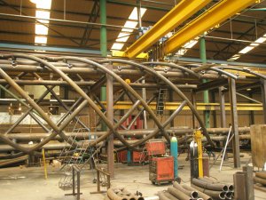
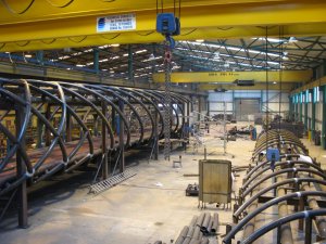
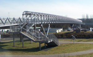
I have over 25 years experience working for complex steel fabrication companies who are market leaders in the UK.I have built jigs to fabricate Bridges,Sculptures and various other large fabrications.
Below is an example of one of the many projects I have worked on.Building the jig for this is no different to building that for a model hull.The only difference is tolerance.You are striving to get within 2 to 3mm over 80metres.
The pics show the 'spiral helix' footbridge for crossing the M8 at Harthill in Scotland,just one of the many 'iconic' projects I have worked on.
Kind Regards
Nigel


Back on track and less about my day job
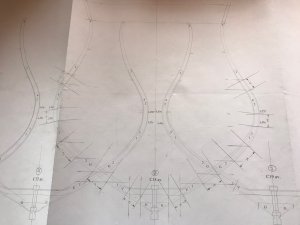
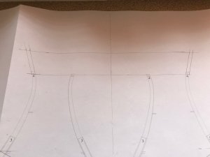
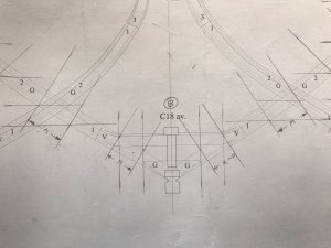
Some pics of the one of the frame sections showing the additional drafting work required.It is necessary to transfer the positions of the mortices to each frame section using the dimensions described earlier.This needs doing separately for every frame and there are over 60 of them
The futtocks can be assembled dry on this elevation and the mortices and tenons marked to enable each futtock and floor timber to be milled accordingly.I am actually thinking about not having any of these plans copied.It would be feasible to build the frames on the plan with a thin layer of acetate between.I thought about a sheet of glass but the thinnest would be 2mm so it may not be so clear that the parts are in line with the drawing.
Also on this view is the frame extensions.These are tangential to the little curl at the frame top.This will make fairing easier and reduce the risk of sanding away this little curl.There will be a timber batten glued across these ends,with the centreline marked.The extensions are for setting the height and position along the vessel not for point of reference across the ships breadth.
I will go into greater detail when I build the jig,I have finalised the design and it is unique in some respects.I have no intention to build it just yet,at 2m by 600mm by 600mm,it is something else to shift when we move house
Kind Regards
Nigel


Interesting - and very special in this dimensions when the planned jig is ",at 2m by 600mm by 600mm," - similar to a coffin
WOW, this will be A ship
WOW, this will be A ship
Hi Uwe
The similarity in size to a coffin didn't cross my mind
Yes the jig is slightly larger than the hull but not by much.It will incorporate my 'unique' clamping system,patent pending


Kind Regards
Nigel
The similarity in size to a coffin didn't cross my mind
Yes the jig is slightly larger than the hull but not by much.It will incorporate my 'unique' clamping system,patent pending


Kind Regards
Nigel
Very impressive, only a pitty that you have to buld a new wing to your house when finished.  .
.
Maarten,why do you think I am moving to a bigger house
Kind Regards
Nigel
Kind Regards
Nigel


