YUANQING BLUENOSE - Don Robinson

@Peter Voogt and @Dean62 these are both great ideas. Something is needed, when I did my few I was reaching inside to push and pull the frames into position which will not work so good as more frames are added. I would like to see your idea Dean, if you have the time. Maybe with some good drawings Heinrich could convince Yuanqing to include something in the kit
First chance I get I will open my kit and take some dimensions so I can look at the best way to do it.
Depending on how much room is at the ends on the jig, it may be possible to get a board and match drill a hole in the center and one on each side of the center hole.
Add a bolt through the side of jig and thru the board, with washer in between the two, and put a nut on the outside. Then put bolt in one hole to the side.
To rotate 180 degrees, take out bolt on side, rotate and put bolt back in. Center bolt obviously always stays in place.
The two end boards would be joined by a horizontal board on each side at the bottom. Make sense?
 
Makes total sense Dean, I think you are really on to something here. A quick measurement shows there is approx. 1/2" of room at the bow and stern, plenty of room for a bolt head and washer.
No need for washer on inside of jig frame, place between jig frame and board on end, as a bushing to aid in ease of rotation.
 
HI DON, AGAIN I APOLIGIZE FOR HIJACKING YOUR LOG, JUST A COUPLE OF QUICK ONES I AM ALSO USING WELLBOND IT IS REALLY SETTING UP VERY FAST NO TIME TO MAKE ADJUSTMENTS, DO YOU HAVE THE SAME PROBLEM, THE OTHE ARE YOU MARKING THE FRAMES FOR THE CUTTING LINE LOCATIONS AND BEAM LOCATIONS AS SHOWN ON FRAE DWG. GOD BLESS STAY SAFE ALL DON
 
HI LAWRENCE, HAVE BEEN THINKING ABOUT THAT, IF THERE IS A CUT OFF AREA AT THE TOP WHERE IS THE TOP OF FRAME HOW DO YOU DETERMINE WHERE THE TOP IS, ALSO IF THIS IS CORRECT WHY S COULD T YOU NOT PUT A STRETCHER BAR ACCROSS TO HOLD THE TOPS WHERE THEY ARE SUPOSED TO BE, JUST A THOUGHT. GOD BLESS STAY SAFE ALL DON
 
HI LAWRENCE, HAVE BEEN THINKING ABOUT THAT, IF THERE IS A CUT OFF AREA AT THE TOP WHERE IS THE TOP OF FRAME HOW DO YOU DETERMINE WHERE THE TOP IS, ALSO IF THIS IS CORRECT WHY S COULD T YOU NOT PUT A STRETCHER BAR ACCROSS TO HOLD THE TOPS WHERE THEY ARE SUPOSED TO BE, JUST A THOUGHT. GOD BLESS STAY SAFE ALL DON
CANOE@!
 
Last edited:
HI DON, AGAIN I APOLIGIZE FOR HIJACKING YOUR LOG, JUST A COUPLE OF QUICK ONES I AM ALSO USING WELLBOND IT IS REALLY SETTING UP VERY FAST NO TIME TO MAKE ADJUSTMENTS, DO YOU HAVE THE SAME PROBLEM, THE OTHE ARE YOU MARKING THE FRAMES FOR THE CUTTING LINE LOCATIONS AND BEAM LOCATIONS AS SHOWN ON FRAE DWG. GOD BLESS STAY SAFE ALL DON
Hi Don, Yes my weldbond is setting up fast too, I thought it was just me and the low humidity in my house. I have not marked the cut off lines and beam lines yet but I will be, I have not made up my mind whether to mark the edges or the face parts of the frames.
 
Hello Don, You sure are making great progress at speeds that make my head spin, Well Done. I have one question and that is why are you using tape to mark your frames # When you could # your frames on the top say 1/2" down this part will be in the cut off area, just my 2 cents worth that's all?
Regards Lawrence
Hey Lawrence, you are totally right, but i am a little bit fanatic about sanding and fairing. So I am afraid if I just mark the frame I'll sand then forget what frame I'm working on! The tape adds a little bit of a safety cushion for me, I know it's over kill! :p
 
HI DON I AM SWITCHING TO MY ELMERS WHITE CARP GLUE, BE CAREFUL OF THE CUTTING LINE MARKINGS CHECK OUT HEINRICHS COMMENTS ON THE LAST PAGE OF MY LOG, GET BACK TO ME IF YOU CAN. GOD BLESS STAY SAFE YOU AND YOURS DON
 
IMG_3849.JPG
The frame factory in full production

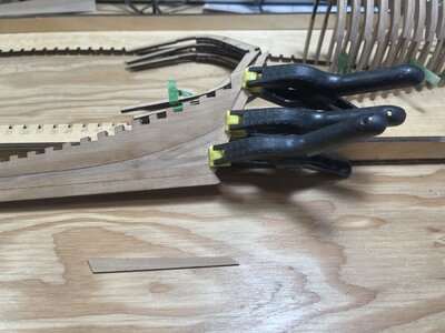
IMG_3852.JPG
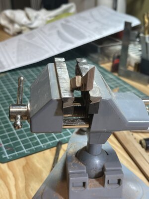
Piece 22 being glued into place, simply remove from billet sand a little char off edges and glue on to keel

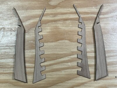
IMG_3853.JPG
Pieces 19 and 65 about to be laminated together. As in the frame assembly be sure to laminate together with the etched bevel lines to the outside so they are visible.

IMG_3869.JPG
The completed pieces

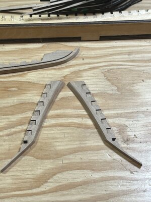
IMG_3864.JPG
I apologise for the picture, I took several but just could not get the piece in focus. I was trying to show the two different bevels.

IMG_3872.JPG
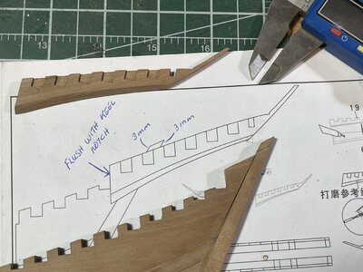
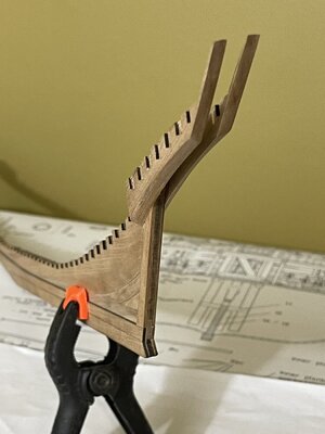
Here I am about to mount the assembly on to the keel. As in the diagram the piece needs to be flush with the notch on the keel and the keel protrudes 3 mm past this piece. I used my calipers to mark the 3 mm then pencilled in the line. This part of the build is the first step that really allows for error so be very careful. This could be avoided if Yuanqing would have laser etched a line on piece 22 to help show the proper position. Not a big deal but with everything else being so exact and precise they fell a little short here. At any rate it is still doable be careful, use the drawings and dry fit several times to be sure of placement.
@Heinrich , maybe this might be something worth mentioning to Yuanqing.

IMG_3873.JPG
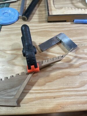
After several dry fits, measuring and a constant sweat I finally grew the b**ls to bring out the glue! I was careful to be sure they were square to each other using the machinist square.

IMG_3875.JPG
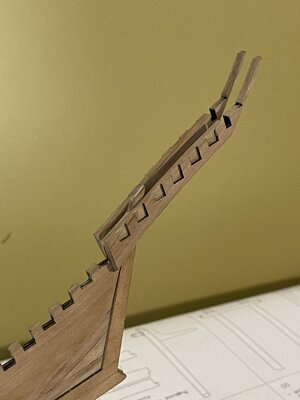
It all worked out in the end and everyone was happy! As Heinrich pointed out notice how these pieces do not sit flush to the top of the keel. A end view of this on the plans would have also helped with the stress level.

IMG_3877.JPG
One final shot, she is looking good and I'm still having loads of fun! :) :p

Have I said Thanks lately Heinrich? Well then, THANKS for this awesome project!!! Thumbs-UpExplosionBeerCoffee-CupOkayGold Star

And Thanks to all of you for stopping in!!!
 
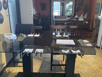
Hi Don Awesome work Don, Well Done. I sure do like your glass kitchen table for a hard flat surface for gluing up your hull frames, this is something that I would not do as my Admiral would not approve of this as a work area.
Regards Lawrence
Lawrence you are welcome anytime you are in the neighbourhood to stop by and use it! :)
 
Good info and build Don, thanks!! I am also blessed with a supportive wife... her dad was a Porsche mechanic and pilot and he always had parts and projects in the kitchen/ dining area - I graduated to the spare bedroom finally.... ;)
 
View attachment 202982
The frame factory in full production

View attachment 202983
Piece 22 being glued into place, simply remove from billet sand a little char off edges and glue on to keel

View attachment 202984
Pieces 19 and 65 about to be laminated together. As in the frame assembly be sure to laminate together with the etched bevel lines to the outside so they are visible.

View attachment 202986
The completed pieces

View attachment 202985
I apologise for the picture, I took several but just could not get the piece in focus. I was trying to show the two different bevels.

View attachment 202987
Here I am about to mount the assembly on to the keel. As in the diagram the piece needs to be flush with the notch on the keel and the keel protrudes 3 mm past this piece. I used my calipers to mark the 3 mm then pencilled in the line. This part of the build is the first step that really allows for error so be very careful. This could be avoided if Yuanqing would have laser etched a line on piece 22 to help show the proper position. Not a big deal but with everything else being so exact and precise they fell a little short here. At any rate it is still doable be careful, use the drawings and dry fit several times to be sure of placement.
@Heinrich , maybe this might be something worth mentioning to Yuanqing.

View attachment 202988
After several dry fits, measuring and a constant sweat I finally grew the b**ls to bring out the glue! I was careful to be sure they were square to each other using the machinist square.

View attachment 202989
It all worked out in the end and everyone was happy! As Heinrich pointed out notice how these pieces do not sit flush to the top of the keel. A end view of this on the plans would have also helped with the stress level.

View attachment 202990
One final shot, she is looking good and I'm still having loads of fun! :) :p

Have I said Thanks lately Heinrich? Well then, THANKS for this awesome project!!! Thumbs-UpExplosionBeerCoffee-CupOkayGold Star

And Thanks to all of you for stopping in!!!
Looking great Don, you're moving along quickly! Is there any reason that piece 22 couldn't be cut off flush with the top? Not sure why the end is proud of the top of the keel? I guess you would have to look ahead in the instructions to see if that piece has any structural use. Otherwise I will cut it off, as it doesn't look right. But only if nothing else attaches to it!!!
 
IMG_3849.JPG
All the clamps and table space I could wish for.... ;)
 
Hello Don, Fantastic work you are doing on your Bluenose, Well Done. I thank you very much for your offer for the use of your glass table but really it is just a bit to far to travel to use it!!! I have a question and that is with the keel glued in place how are you installing your hull frames, are you installing them from the bottom or popping them into place from the top? I guess that I am overly curious.
Regards Lawrence
 
Back
Top