YUANQING BLUENOSE - Peter Voogt [COMPLETED BUILD]

How do you all make the blocks and how tight must the fit be?
Measure the distance between the adjacent fwd and aft frame faces from the drawing. I'm not sure about the exact dimensions anymore.
For starting material something like .20 by .40 will work.
 
Sometimes you put a picture in your build log, where you see things that make you think: how could that have happened. :confused:
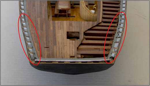
After finishing the deck planking and the 1st layer of oil, I placed this photo:
721721 Waterway.jpg
I had made the recesses in the waterways tight and yet these holes are visible. See inside the red ovals. That bothered me a lot and I had to do something about it. And no one responded like: Hey Peter, how about that? :rolleyes:

Started with putty and small scalpels. And checked both sides along the entire length. Once a lot tighter, the waterways repainted. And also painted the inside of the bulwark white.
By painting the waterways gray, in accordance with The Saga, I did not make it easy for myself. It is a lot of work to tape everything around the 2x57 stanchions. So only done with a small brush and a lot of patience.
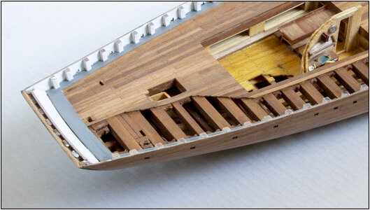
This one looks cleaner:
722 Bulwark.jpg
At the same time, the heads of the stanchions and the edge of the hull were sanded flat so that the Main rail can fit tightly.
Regards, Peter
 
Last edited:
Sometimes you put a picture in your build log, where you see things that make you think: how could that have happened. :confused:
After finishing the deck planking and the 1st layer of oil, I placed this photo:
721View attachment 307391
I had made the recesses in the waterways tight and yet these holes are visible. See inside the red ovals. That bothered me a lot and I had to do something about it. And no one responded like: Hey Peter, how about that? :rolleyes:

Started with putty and small scalpels. And checked both sides along the entire length. Once a lot tighter, the waterways repainted. And also painted the inside of the bulwark white.
By painting the waterways gray, in accordance with The Saga, I did not make it easy for myself. It is a lot of work to tape everything around the 2x57 stanchions. So only done with a small brush and a lot of patience.
This one looks cleaner:
View attachment 307392
At the same time, the heads of the stanchions and the edge of the hull were sanded flat so that the Buffalo rail can fit tightly.
Regards, Peter
So you were testing us Peter?
If I had known that beforehand... ROTF
To be honest, I had similar issues with especially those aft waterways. I even made a few new ones.
Initially I blamed YQ for poor parts design, but it appears that due to being a member of the BFC, I had some frames to repair. One of those repairs was performed rather poorly, resulting in that frame being out of position. Hence the waterways didn't fit; so I'll find myself in a similar position, filling and filing, since my handmade waterways are of a looser fit than the YQ ones...
 
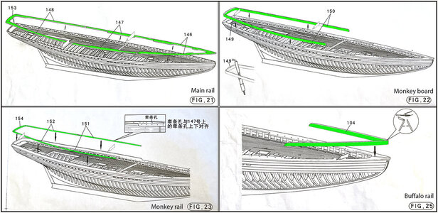
The next step in the construction is assembling the bulwark. The manual shows that in 4 steps:
723 Bulwark.jpg
With the special feature that there are small recesses in the Main and the Monkey rail through which the Chain plates have to be inserted. Those 2 must therefore be properly aligned so the chain plates are directed in the right direction towards the tops of the masts.

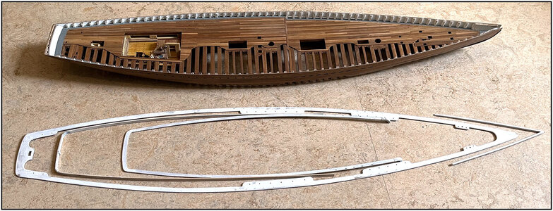
The parts composed:
724 Bulwark.jpg
I want to place these all, finished in the primer, on the hull so that I can spray them seamlessly white afterwards. Only the Monkey board remains on the starboard side in the bare wood for oiling later. On the port side it gets the blue-black ink. Ditto with the outsides of the Buffalo rail. I tape those sides so the spraying can still be done in its entirety.

But .........
While fitting and drying the paint I also auctioned off the recess for the bowsprit. And I soon realized that I couldn't place it if I first mounted the railing.
Because ........
I use the aforementioned Saga and Chapelle's book as inspiration for implementing the additional details. But also the construction drawings of the BN of Model Shipways. The building report of this model from the already mentioned 'Suburban Ship Modeler' is also inspiring.

YQ places the regular round bowsprit, which could possibly be placed with a slightly enlarged hole. But then the details have to be added later.
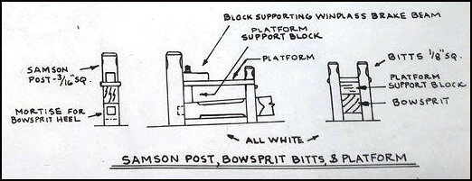
However, MS shows a square beginning of the bowsprit:
725 Bowsprit.jpg
Here I will also have to adjust something on my model because the 'bits, the front 2 uprights along the bowsprit, are slightly further apart.

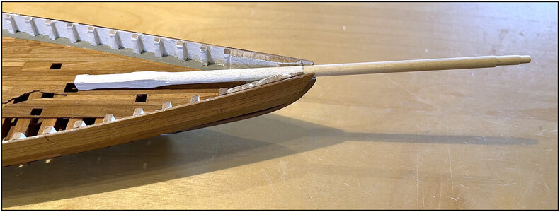
Started making this square beginning and the stepped shoulders at the tip:
726 Bowsprit.jpg
The spar shortened and the square part is attached to the spar with a pin.

Together with the further preparation of the railing parts, I now continue with the construction of the bowsprit, with the Samson, the platform and all the fittings that need to be put on it.
Thinking a bit ahead may therefore pay off again.;)
Regards, Peter
 
Last edited:
The spar shortened and the square part is attached to the spar with a pin.
So basically you shortened the cylindrical part of the bowsprit and, in order to maintain the correct length, added a square piece, which has the length of the removed part. And that replacement part is square in order to match the MS geometry.
Impressive!
 
So basically you shortened the cylindrical part of the bowsprit and, in order to maintain the correct length, added a square piece, which has the length of the removed part. And that replacement part is square in order to match the MS geometry.
Impressive!
Almost, in a little different order, Johan. First made the square piece on the YQ measurements between de Samson and bott bitts and from square to round before the bitts in the diameter of the bowsprit. And that length I cut of the bowsprit. ;)
 
Hi Peter.
I have read through your build log last week and have absolutely enjoyed it as you must have noticed by the stream of likes, loves and wows. It reads like an exciting book with twists and turns. All superlatives have already been justly used and you have even become a "BN" in China. In this case BN not meaning BlueNose (coincidence?) but the Dutch expression for "Bekende Nederlander" - a "Well known Dutchman".

I am fairly new to this forum and the "Group Build" was new to me. Nice to see that you all learn from each other and help each other. That is very valuable, as is your "middleman" Heinrich.

You work has been extremely fine and crisp and especially you putting the saw (beautifully executed) in the hull took me by surprise but produced a very special model. Taking a risk using ink on your model also was also an exciting chapter in your build log. Again it delivered a great result. And so on..

I will be watching your progression with great interest.
Hi Herman,
Through the likes I could indeed see that you were going through my build log. Thank you for your interest and your post.
The Group Builds are a wonderful phenomenon here at the SOS. For help with questions, showing solutions and, as in the case of the BN, so far 22 different BNs have arisen from the same package.
Enjoy participating in the SOS.
Regards, Peter
 
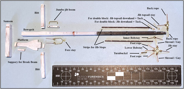
To no longer have construction work on the bowsprit when installed, first made and collect all parts:
727 Bowsprit.jpg
For myself as a manual I also added all names what will be applied where.
I kept the eye pins on length. Those will be shortened later, especially the one that forms one side of the 'turn-buckels'. The turn-buckets will be made from 1.3mm brass tube.

The next steps:
- gluing and painting the wooden parts;
- the end of the bowsprit with blue-black ink;
- the copper parts 'blacken';
- put everything together and fit.

Thanks to Dean's @Dean62 tip: he used the edges of the photo-etched parts for the brackets at the end of the bowsprit. Everything bent and no need to solder.
Regards, Peter
 
Last edited:
After some questions on the Dutch forum, a picture how I glue the frames.
Working from frame 25, alternately a frame to the bow and to the stern.
Perhaps a overkill, but .....
View attachment 232806
-a frame with a clamp on the keel, to prevent it from being pulled down when further tightening;
- glued the ends of the frames into the jig and tensioned them in the frames with a slat. Under the jig a few frame boards because I have the jig on 2 aluminum profiles for perfectly flat. So the ends will not go lower then the underside of the jig;
-between the frames fit exactly 2 frame boards. Because some rafters are slightly curved (or not 90,000 degree angled overall ;)) and now dry right next to each other.
Regards, Peter
Great how-to Peter! Thanks for the functional pictorial - I've been wondering how the glueing goes!
 
Before placing the frames I took the time to align the keel and 1st frames well: straight and at right angles, in a longitudinal and transverse direction.
Other than the manual, I've followed the advice in this interesting post from Dave @Dave Stevens (Lumberyard) in the Druid build-log from Donnie @Donnie :
Special this lines:
“Never ever start at one end and work you way to the other end.
I will always set the midship frame up and the last whole frame forward and aft. Then set up a frame between midship and those last whole frames. Then I will fill in the rest of the frames.”

This became the setup:
View attachment 232786
-1st, the frames 1 and 49;
-2nd , I added the 2 half frames 50 and 55, because they are glued on the side of the keel and ensure ideal vertical alignment;
-3th , frame 25 halfway;
-4th , frame 13 and 37 in between.
According to the hook by frame 25, everything is straight. :)

BUT: See the insert picture above-left. Before I started placing the frames, I first made the bevel in the top of the rabbet on both sides of the keel. Which is much discussed here in the Bluenose Group Build Logs. With the keel separate from everything, it could be nice and flat on my work table with a small chisel.
Now the noses of the frames fits nicely to the bevel and the hull planks (garboards) can slide from the frames into the rabbet. Once all frames have been placed, I can adjust the bevel definitively.
Note: It is just my AL-FI, nobody has to follow this up.Speechless

And for the vertically alignment this photo:
View attachment 232787
Taken with the stern to the camera. You never get everything in focus over that length. (Or you have to stich several pictures from 1 fixed point of view with different stages of focus) Therefore, the sharpness is chosen on frame 1. The silhouette of the double back piece still shows itself nicely on either side. To check that everything is straight and parallel to each other.
PS: Sorry Jim @Jimsky still not a cathedral.

All in all, this already gives a lot of strength. A good basis for the rest of the frames.
Regards, Peter
More awesome advice and well-illustrated to assist first-timers with critical awareness from the pro sum knowledge as to how it's best done!
 
First I started assembling the keel part of the stern.
Dean @Dean62 has introduced ‘Artistic License’ (AL). I will add ‘Free Interpretation’ (FI). Together it is AL-FI. :D

So, AL-FI says:
The manual describes to glue these 2 longitudinal parts to the keel.
I chose to put them together separately. Together with part #53, which actually is on page 14 in step/photo 82/83. But I think that part gives more solidity:
View attachment 232438

Because I was busy with all parts of the stern, also these parts were prepared dry-fit:
View attachment 232439
After fitting on the keel, it will be adjusted on bevel and angle.

I then fitted the keel part, together with the half frames 50 and 55, to the keel. With the smooth connection to the frame 49:
View attachment 232440

Taken away frame 50 and the keel part glued and clamped:
View attachment 232441

The whole construction of the stern is depending of this joint. So I believe the connection of these main parts is not only glued. I have, with AL-FI, chosen to strengthen the connection of the stern part to the keel.
I used the technic I encountered in the build-log of Maarten @Maarten :
But also Jim @Jimsky gives a nice explatantion in his Alert build-log about the cup burr and the treenails with a syringe.
The cup burr must be bigger then the wire, or the wire has to be pointed. Otherwise the cup burr won’t center:
View attachment 232442

With brass 1,2 mm and a cup burr of 1,2 mm, a made 6 rods/nails:
View attachment 232443
There is some brass in the burr, forgotten to clean it for the picture. ;)
The construction:
View attachment 232444

In detail:
View attachment 232445
The angle of both parts is the same as on the drawing of the manual. Practice and theory come’s (again) together.

Perhaps you won’t see it any more when the build is completed, but ..... you know it’s there.;)

So, now I am ready the glue the frames in the jig and on the keel.
Regards, Peter
Just like me - why go for nominal when you can go failsafe! Onward and upward!
 
Great how-to Peter! Thanks for the functional pictorial - I've been wondering how the glueing goes!
Hi Joe. Thanks for your reply and the compliments. I suppose the glue question was rhetorical ;)
More awesome advice and well-illustrated to assist first-timers with critical awareness from the pro sum knowledge as to how it's best done!
‘The Best Way’ is for many builders different. It depends on skills, equipment, experience etc. But thanks to all the build-log, it can give you a direction to find yours.
Just like me - why go for nominal when you can go failsafe! Onward and upward!
By scratch building my Lee I had to interpret things myself, invent things, read materials, etc. Then you sometimes get creative 'out of the box'.
Regards, Peter
 
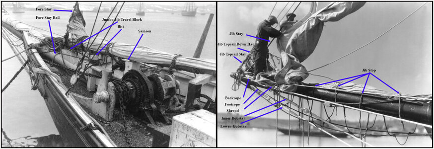
As with the aft deck, I also have some old photos as a source of inspiration for the foredeck and the bowsprit:
728 Bowsprit.jpg
Here I also put all the names that I mentioned in the parts overview.

It took some time before I could place the bowsprit. I was not satisfied with the first paint result and I took everything apart again, sanded it and then mounted it in place. Then carefully removed from the deck and sprayed.
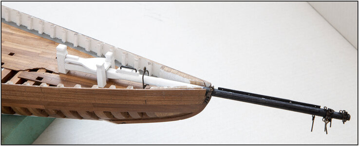
Then mounted all brackets and eyes, carefully slid back into the deck openings and glued:
729 Bowsprit.jpg
In my enthusiasm I had applied a little too many eyepins for the turnbuckels. On the bowsprit itself there will be 4: for the 2 Bobstays at the bottom and the 2 shrouds on either side. The Back ropes has the turnbuckles nearby the hull.

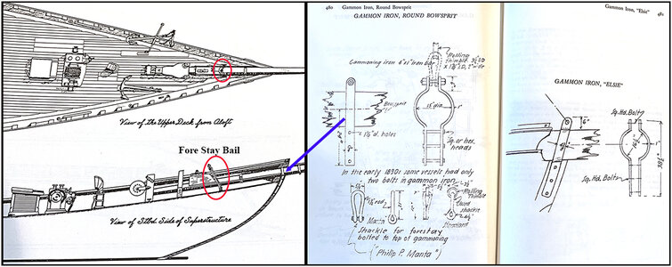
YQ mentions placing an eyelet for the later attachment of the Fore Stay. However, the old photo, the Saga and MS drawings show a bail that runs over the bowsprit and is attached to the deck with 2 eyes.
And Chapelle wrote a few pages about the Gammon. A jump bar that runs over the bowsprit and is secured to the keel beam.
730 Gammon.jpg
I made them myself. On top of the Gammon a M 0.8 mm bold and nut. Still in stock from another model building period.

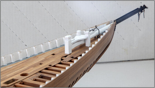
Forward view:
731 Bowsprit.jpg

I made the applied fittings from brass wire and residual material from the etched parts. It stands out nicely when you apply this 'copper colour'. But I stay more or less in the style of the original BN and have it blackened. It is not completely black, but more or less 'tanned' with Ballistol "Buntmetall-färber. They also call it 'browning'. I also have a jar of "Schnell-Brünierung", but the applied layer quickly fell off.

Then I can now continue building the bulwark.
Regards, Peter
 
Last edited:
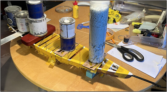
And after the intermezzo of the bowsprit, I now could glue the Main rail. Used the same technique as by the curved roofs of The Lee.
A lot of tape and weight:
732 MainRail.jpg
The 2x4 brass strips that protrude through the rail will later be used to make the chain plates. Now they stick through the holes and I taped them to the hull. So that the rail protrudes over the edge of the hull at the correct distance in those places. And I used that distance again to further align the rail.
Now it can rest for the night and tomorrow I can see how it connect to the hull. Not being able to discover many seams with some backlight.:)
Regards, Peter
 
Last edited:
Back
Top