Sawing is now faster. Almost like a life stream. ") I am through the wide rounded rear parts and now at the narrower more upright parts.
I am through the wide rounded rear parts and now at the narrower more upright parts.
The photos are not the best. I still have to get used to turning and choosing position with this large jig to get a good image crop and lighting. Laying on her side is not a option.
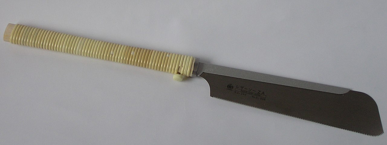
With saw:

Without saw

I can now lay the planks on the stringers and go sawing backwards.")
The saw cut:

And with a little dimension:

Regards, Peter
I am through the wide rounded rear parts and now at the narrower more upright parts.The photos are not the best. I still have to get used to turning and choosing position with this large jig to get a good image crop and lighting. Laying on her side is not a option.
With saw:
Without saw
I can now lay the planks on the stringers and go sawing backwards.
The saw cut:
And with a little dimension:
Regards, Peter
Last edited:

 It needs almost no tension.