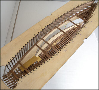
YUANQING BLUENOSE - Peter Voogt [COMPLETED BUILD]

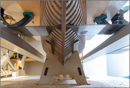
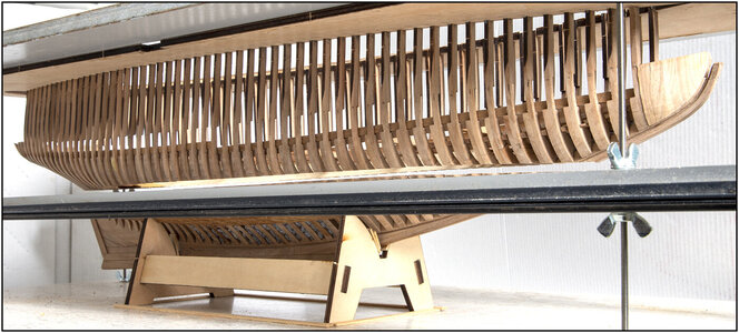
Sawing is now faster. Almost like a life stream. ;) I am through the wide rounded rear parts and now at the narrower more upright parts.
The photos are not the best. I still have to get used to turning and choosing position with this large jig to get a good image crop and lighting. Laying on her side is not a option.
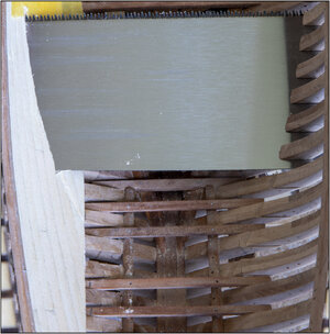
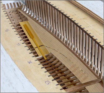
With saw:
276 Cut.jpg
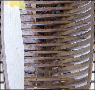
Without saw
277 Cut.jpg
I can now lay the planks on the stringers and go sawing backwards. :)

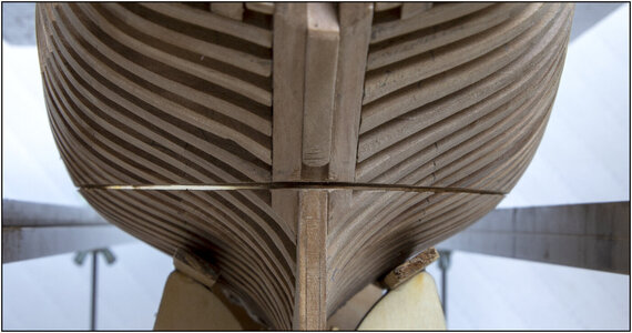
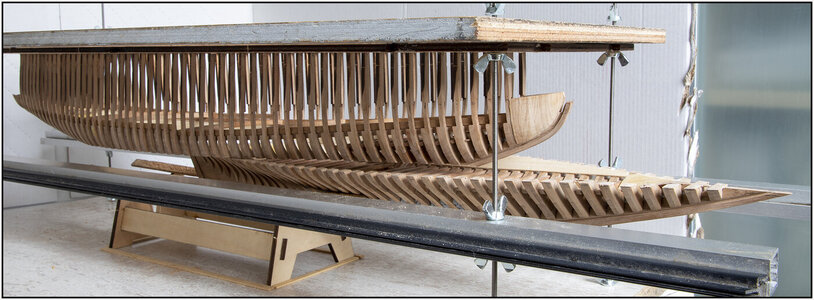
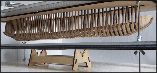
The saw cut:
278 Cut.jpg
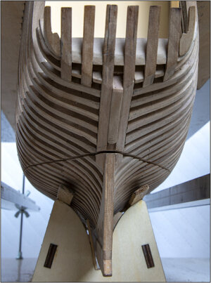
And with a little dimension:
279 Cut.jpg

Regards, Peter
 
Last edited:
Sawing is now faster. Almost like a life stream. ;) I am through the wide rounded rear parts and now at the narrower more upright parts.
The photos are not the best. I still have to get used to turning and choosing position with this large jig to get a good image crop and lighting. Laying on her side is not a option.
With saw:
View attachment 250286
Without saw
View attachment 250287
I can now lay the planks on the stringers and go sawing backwards. :)

The saw cut:
View attachment 250288
And with a little dimension:
View attachment 250289

Regards, Peter
In my mind that even with the thinking and preparation your courage to commence and continue the sawing is remarkable. That saw in your hand is a surgeon's scalpel. Nicely done. I'll keep my fingers crossed for you. Rich
 
In my mind that even with the thinking and preparation your courage to commence and continue the sawing is remarkable. That saw in your hand is a surgeon's scalpel. Nicely done. I'll keep my fingers crossed for you. Rich
Thanxs Rich. The advantage: the saw is razor / scalpel sharp. They also gave advice when buying the saw: do not guide the saw with your fingers when a new start is made. :D It needs almost no tension.
Regards, Peter
 
Thanxs Rich. The advantage: the saw is razor / scalpel sharp. They also gave advice when buying the saw: do not guide the saw with your fingers when a new start is made. :D It needs almost no tension.
Regards, Peter
This is late in my present sawing needs but I would like to know your source for that. I can see that it is superior to those that I have now. Thanks, Rich
 
For all the sympathetic forummers: a (saw) update.
The planks of the ceiling on the port side inside is in place till beyond the saw cut:
View attachment 250261
When I have the two parts apart, I finish the wall and the connection with the floor. Then I can do better. Because now I was bent over to work with 2 big hands in the hull. Fortunately, a row always had to dry before the next could go in. So I was also able to relax my back.

In the Saga only the length of the outside planks is mentioned: between 25 and 30 feet. That is between 7.6 and 9.1 meters. In 1:72 that is 10.5 - 12.6 cm. I kept around 12 cm / 4.72". Then a plank is laid over 12 frames. I put them in a wild bandage. Once the inner walls are in, I'll look at how the seams are divided and visible. Then you can always make new ones.

With the sawing I have now passed through the stringers, arrived at the ceiling and through the first 2 frames where the sawn upper parts are partly hanging free:
View attachment 250262
In the end, only 1 floor beam had to be removed from the stringers.
And a relief: there is almost no movement in the now freely hanging frame parts. Or you have to go rough. Then the 'premeditated' connection of glues and nails with the bearing beams has proven its reliability.
Another relief: all now visible sawing angles and distributions of beams are very symmetrical on both sides. Phew......

On the intended saw cut I stuck on the planks (gaffer) painter's tape as extra protection to get a nice saw cut.
When I am more than 1 saw blade width further, I lay the floor boards on the stringer beams. Then I turn the saw over and saw through those planks. Then I press the saw against the planks/trusses. And that saw cut is also flush with the rest.

So still, step by step and keep thinking about the possible in-between steps.
Regards, Peter
Good progress Peter! My only concern is sawing through tape…that can get the tape glue on the saw blade and make the saw gummed up and hard to cut. In addition it could get smeared on the wood. Hopefully it doesn’t cause problems.
 
The half springer floor has been laid and sawn in half:
280 S-Floor.jpg
When the parts are apart, the edges are sanded neatly aligned.
I used 3x1mm palm wood for the floor. In the middle a few pieces that have been put in the linseed oil twice and immediately get a warmer shade.
It stands out nicely against the lime wood of the walls. The standing dividing walls are also lime, so a mark with that too.

I am now halfway through sawing. I'm taking a break with sawing because the hull above the waterline has 'some flexibility'. Not worrying, the whole keeps its shape nicely. So no problem with sawing. I just thought: Let me feel the sawn part.
But first I'm going to apply the clamps in the back part:
281 Clamp.jpg
So that I can then fit 9 deck beams (which have no cross connections) over the entire length of the hull to give this upper part extra strength. Thanxs Dean for this advice!
Just used common sense and don't just keep going.
Regards, Peter
 
Last edited:
The half springer floor has been laid and sawn in half:
View attachment 250549
When the parts are apart, the edges are sanded neatly aligned.
I used 3x1mm palm wood for the floor. In the middle a few pieces that have been put in the linseed oil twice and immediately get a warmer shade.
It stands out nicely against the lime wood of the walls. The standing dividing walls are also lime, so a mark with that too.

I am now halfway through sawing. I'm taking a break with sawing because the hull above the waterline has 'some flexibility'. Not worrying, the whole keeps its shape nicely. So no problem with sawing. I just thought: Let me feel the sawn part.
But first I'm going to apply the clamps in the back part:
View attachment 250550
So that I can then fit 9 deck beams (which have no cross connections) over the entire length of the hull to give this upper part extra strength. Thanxs Dean for this advice! Just use your common sense and don't just keep going.
Regards, Peter
Looking good so far Peter! You are using a systematic approach, that has to be thought out carefully every step of the way, and adjusted accordingly as you go. You are doing good! I have faith this will turn out very nice! ;)
 
Looking good so far Peter! You are using a systematic approach, that has to be thought out carefully every step of the way, and adjusted accordingly as you go. You are doing good! I have faith this will turn out very nice! ;)
With your approach you really are sailing to the dark side of the moon solo. Successful landing in several ports along the voyage so far. Best of luck and care as you continue your voyage that carries all of us along with you. Rich
Thanxs Dean&Rich for actively experiencing this adventure :)
Regards, Peter
 
The rear 2 clamps also fitted. Then 4 more deck beams were made to measure and attached:
282 Clamp.jpg
This clearly gave even more firmness to the hull.

Continued sawing up to the last cut:
283 Saw.jpg

The jig in which the frames are attached, turned up a bit:
284 Up.jpg

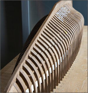
The ‘below the waterline’ part could be pushed forward:
285 Forwards.jpg

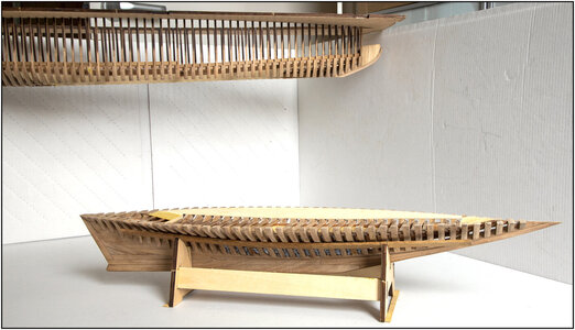
And ‘above the waterline’ part free:
286 Free.jpg

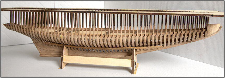
The bottom back on the temporary stand:
287 Bottom.jpg

The waterline model:
288 Waterline.jpg

And merged again:
289 Samen.jpg

Regards, Peter
 
If I want to show the model with a whole hull again, the frames no longer overlap nicely. Because the saw cut has removed a layer:
290 Naad.jpg

That is why a white strip has been applied to the starboard side at the thickness of the saw cut. And then I immediately have a nice right waterline stripe over the entire length:
291 Line.jpg
Port side will come later, because the planking still has to be put on there first. And the waterline strip must connect nicely with that.

I mainly want to show the model with the two parts of each other. So you can also see the interior. Because that's what it was all about for me.
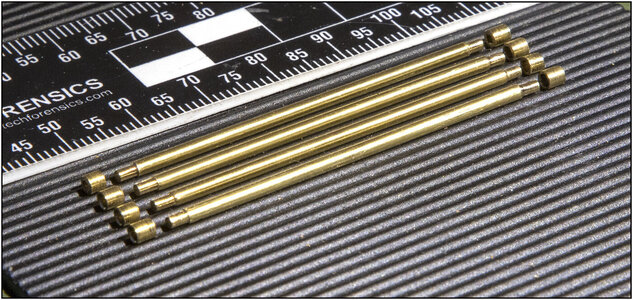
From 2.0 mm brass rod 4 supports of 50 mm with 2.5 mm long pins made on the lathe.
From 2.5 mm brass tube 8 bushings of 2.5 mm height made:
292 Stands.jpg

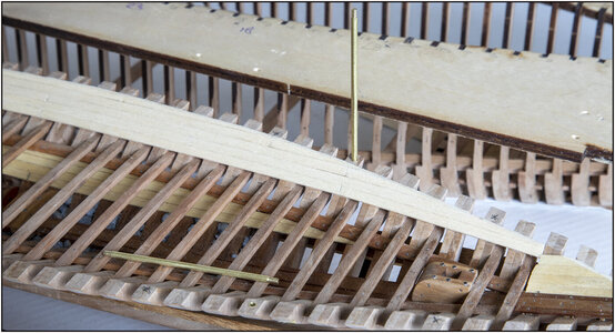
After the necessary measuring, a hole of 2.5 mm diameter and 2.5 mm deep was drilled on both sides. Yes, measure very carefully that the holes did not go through the frames. Fit, measure, fit, measure …….:
293 Stands.jpg

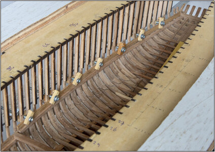
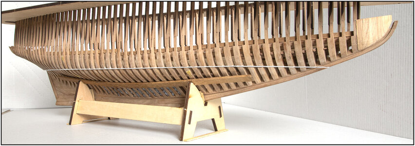
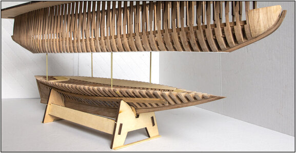
And then it all looks like this:
294 Stands.jpg

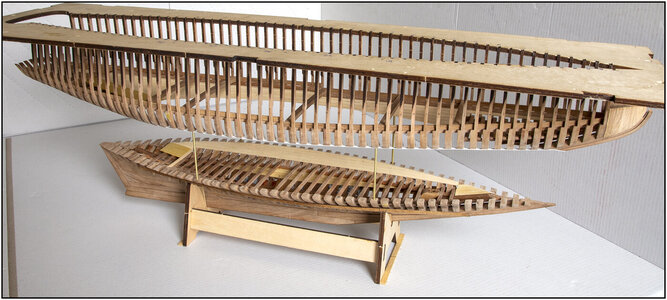
Slightly more from above with more view of the inside work:
295 Stands.jpg
With later the floors and walls of the front and rear cabin and 2 'fish holds'.

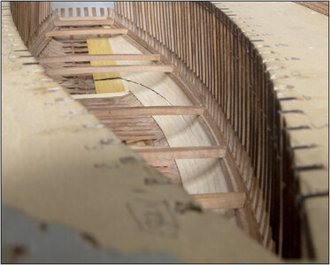
And from above, with a view through the deck beams:
296 Stands.jpg

Regards, Peter
 
Last edited:
Very well done Peter!
The lower portion is very shallow, therefore it seems the parting line may have been higher IMHO, just below the deck beams to show more in the lower half? However I am sure that would interduce other problems, as you would have to cut a curve to follow the deck.
I am interested to see how much of the main cabin will be seen, if any, in the lower half? It looks like that will be in the upper half?
Anyway, once again I think you did a great job of parting the ship. Where to cut it is always going to be subjective. ;)
One final thought...if the main cabin will be in the upper portion, perhaps you could have the cabin roof be removeable? Also, how will you address the masts?
 
Last edited:
Back
Top