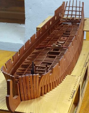
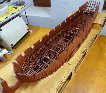
HMS Blandford POF by Keith [COMPLETED BUILD]

But Keith obviously had no issues with the instructions,at least I didn noticed that he complained about it
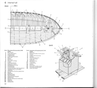
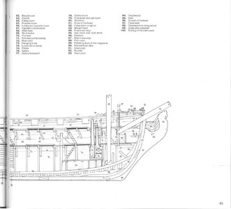
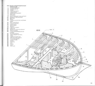
There is very little in the way of written instructions provided with this kit. A manual is available to download from the internet with 3D drawings of each part of the build. They are relatively easy to follow with a bit of thought. All the other details and measurements can be got from the excellent scale drawings of the hull, both side and top views. This is not the kit for a beginner
 
There is very little in the way of written instructions provided with this kit. A manual is available to download from the internet with 3D drawings of each part of the build. They are relatively easy to follow with a bit of thought. All the other details and measurements can be got from the excellent scale drawings of the hull, both side and top views. This is not the kit for a beginner

in the uk this is 70.00 at Amazon
Yes it is, but this is for a 5 ltr tin and l don't think you are going to need that much unless you plan to paint the whole house as well :D . l have a 750 ml tin and l estimate that giving the whole model 2 coats will use approx. 1/4 tin
 
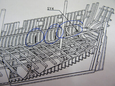
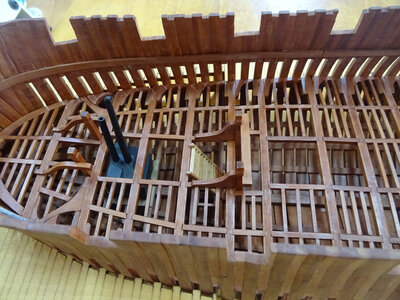
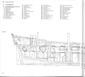
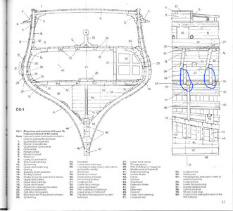
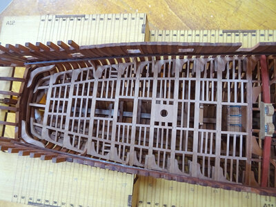
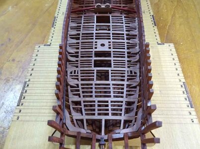
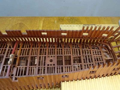
I have a question, can anybody help? l have now reached the stern section of the lower deck timbers of this build and, unless l have interpreted the 3D drawing in the manual wrongly, the hanging knees of most of the last 6 deck beams are actually not ''hanging'' at all, but are fixed upside down to all the rest. The parts supplied with the kit are a different shape and are not made to go the other way, so l assume this must be correct although l have checked with the Anatomy book and can find no reference for them to be any different from the rest. Any suggestions please?

DSC05480.JPG
 
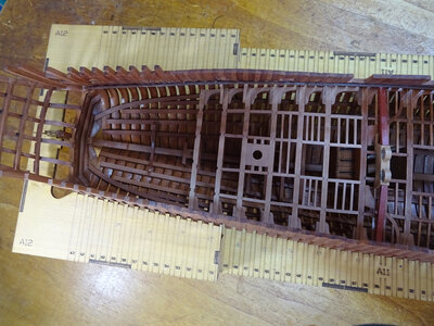
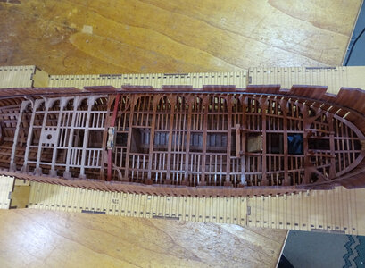
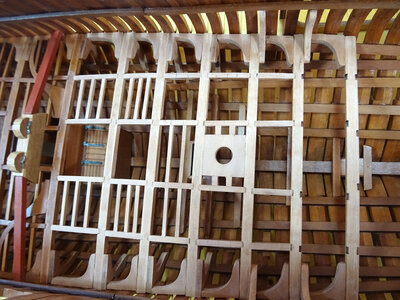
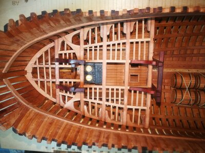
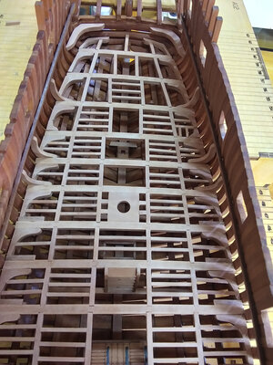
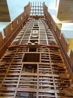
Continuing work with the lower deck, stern section. The circular aperture in the middle of the deck between beams 15 and 16 is a support for the central column of the capstan which will be made up later. The upright ''hanging knees'' are not interfering with any structure so l will carry on as per the kit instructions. lf this is not technically accurate, it's not really a problem for me :)

DSC05486.JPG

DSC05487.JPG

DSC05489.JPG

DSC05494.JPG

DSC05496.JPG

DSC05497.JPG

DSC05503.JPG

DSC05505.JPG

DSC05507.JPG

DSC05511.JPG

DSC05513.JPG
 
Others may know the correct name, but part SY4 is not a hanging knee for deck beams at all, but a horizontal corner brace to help keep the stern square to the side of hull and to help prevent twisting and warping of the rear of the ship.

I see these in many small boats all the time and in other builds as well. You normally wouldn't see them in POB builds just these high quality POF kits.
Thank you for your reply Kurt but l'm not referring to part SY4 but the four darker parts circled in blue on the drawing which are definitely knees
 
I have a question, can anybody help? l have now reached the stern section of the lower deck timbers of this build and, unless l have interpreted the 3D drawing in the manual wrongly, the hanging knees of most of the last 6 deck beams are actually not ''hanging'' at all, but are fixed upside down to all the rest. The parts supplied with the kit are a different shape and are not made to go the other way, so l assume this must be correct although l have checked with the Anatomy book and can find no reference for them to be any different from the rest. Any suggestions please?

View attachment 335718
Your understanding is correct, this a few knee is upward, the anatomy of the book have the knee of the installation drawing.

000.jpg58.jpg
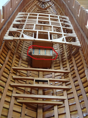
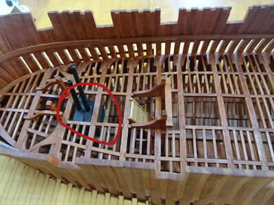
See your build pictures feel have a little problem, one is the storage of ammunition storage cabinet hinges on the skylight of installation position has a problem, and the wrong direction of the installation of boiler, should put the position of the POTS towards the bow.

DSC05336.JPGDSC05513.JPG777.jpg555.jpg999.jpgIMG_20220429_031524.jpg
I'm sorry to have said that, if there is any inappropriate place, please forgive me.
 
Your understanding is correct, this a few knee is upward, the anatomy of the book have the knee of the installation drawing.

View attachment 335798View attachment 335799
See your build pictures feel have a little problem, one is the storage of ammunition storage cabinet hinges on the skylight of installation position has a problem, and the wrong direction of the installation of boiler, should put the position of the POTS towards the bow.

View attachment 335814View attachment 335815View attachment 335812View attachment 335811View attachment 335813View attachment 335816
I'm sorry to have said that, if there is any inappropriate place, please forgive me.
Thank you for your help. Very much appreciated. I did notice that the boiler was the wrong way according to the book but the instructions had it this way round so the chimney points aft and the stove tops would be too close to the fore mast position imo. No apologies needed, you are absolutely correct. Love your build btw.
 
Hello Keef, I too have been pondering the position, and indeed the type, of galley stove on Blandford. I think you are correct in placing the flues forward of the hot plates/kettles. Goodwin in AoS shows the stove to be made of brick but the design is that of a later type iron firehearth. When Blandford was built she would defiantly have had a brick stove as iron ones where not in service until 1730's. The stove that came with the kit (at least the one that came with mine,) is clearly meant to be an iron one. ` Blandford did get an iron stove in 1732 as stated by Goodwin from public record sources, so most likely true. However he then goes on to say that 'in later years the galley was placed under the forecastle'. On the upper deck under the forecastle would be the normal place for the stove of a small English MoW and this is where I would have liked to have placed it on my build, except there is no room.
So all this suggests to me that the stove, even after changed to iron, was always on the fore platform and in the orientation you have it. Also if I use the iron stove included I am building a post 1732 ship. Just as well, as the gun carriages that come with the kit are also of a design only developed in the 1730's and almost certainly a type never used on the Blandford, but that's another story.

Your build looks great and is an inspiration to me. Cheers JJ.
Thank you very much for your informative reply Jack, l see you've done a lot of research into this and it's very useful. l don't think l shall worry too much about the gun carriages when l get to that stage, as before you mentioned it, l would've had no idea :) . How is your Blandford coming along? l would love to see some pics if you have any. Not too many people post their Blandford builds. Thanks for your kind words and l hope you are enjoying it as much as l am.
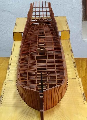
 
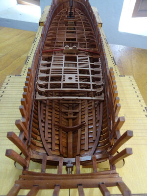
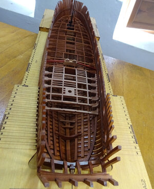
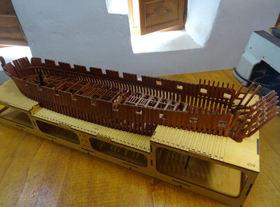
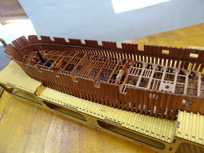
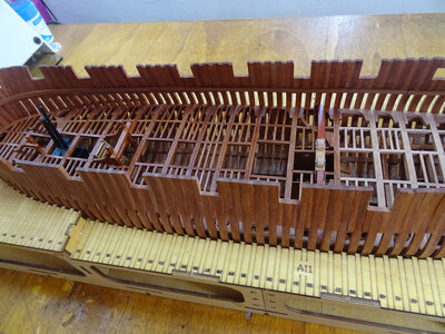
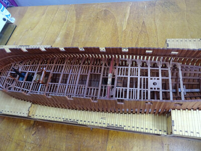
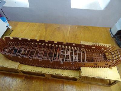
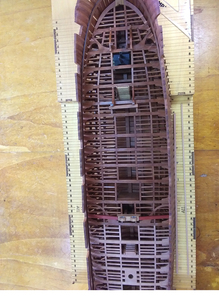
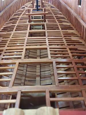
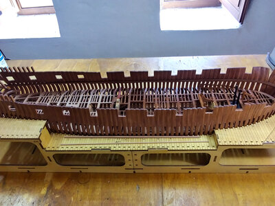
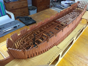
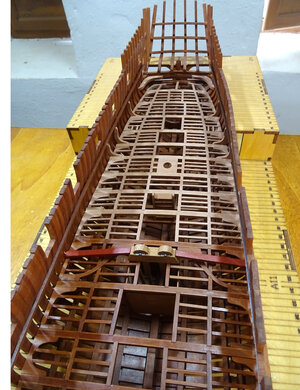
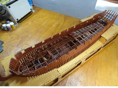
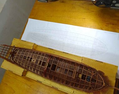
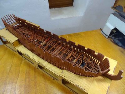
lt's exactly 7 months to the day (31st April 2022) since l ordered this HMS Blandford POF kit from Modelship Dockyard and today sees the completion of the keel, ribs, platform deck and lower deck timbers. Maybe just over halfway through this project, but who's counting. This is my first attempt at one of theses kits and l've enjoyed every day of it, so really will be quit at a loss when it's finished. Seriously thinking ahead for my next build and will have to consult with Uwek about the CAF Granado full hull kit, if you don't mind

DSC05514.JPG

DSC05520.JPG

DSC05522.JPG

DSC05524.JPG

DSC05537.JPG

DSC05539.JPG

DSC05548.JPG

DSC05551.JPG

DSC05553.JPG

DSC05563.JPG

DSC05564.JPG
 
Your work is extraordinary! Im Jealous of my own skills. I can tell you that the CAF enterprise is a GREAT kit, also Tom at Caf is telling me that he is doing the lower decks and interior for the La Rennomme kit.... Also Im looking at the DLumber Confederacy kit, have you any feedback on it? Thx, Paul
 
Hi Keef,

I've been following your build report since the beginning. I am thrilled. What a fantastic overall impression. Congratulations zz the state you have worked out now. It really inspires me. Thanks for showing it. Yesterday for my birthday I received the matching book. I will continue to follow your Bauberich with great enthusiasm.
Greetings Karlheinz
 
Back
Top