LE ROCHEFORT

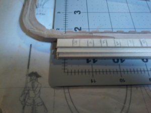
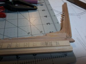
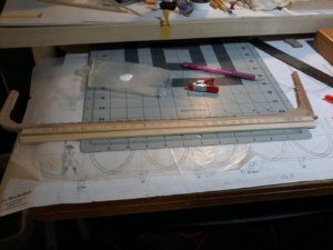
NOW ANOTHER ITEM AND I DO NEED ADVICE ON THIS ONE PLEASE TO ALL CHIP IN i have been mulling over in my mind about installing the frames on my BUILDING JIG/SLIP, witch takes up a tremendous amount of room would have to do it in my SON-IN-LAWS office garage, witch i would like to avoid if at all possible soultion HOBBY ZONE THROUGH THERE US DISTRIBUTOR $34.00 versus $119.00 could be a solution here is what i was contaplating the max. keel thickness is 5mm the Le Rochefort keel is 7mm my solution see pictures is this need input please, please the upper part of the temporary extention is a piece of 7mm basswood temporally glued in place with the frame Nos. added two 5mm pieces, does anyone see any problems here, i orignally addedthe 7mm piece so the frames would be elevated and not touch the bottom, SO ALL CHIP IN HERE20200303_201055.jpg20200303_201312.jpg20200303_201654.jpg
 
i am doing a sample of the transom witch i want to do half and leave the other half open, as best i can determine the planking is 1/16 inch thick wonder if i could use a thin piece of basewood just shy of 1/16, then use planking,

1) You must be talking about the stern, not the transom.
Please make sure you re-measure the thickness of the planking in that area. Looks like it is much less than 1/16". more like 3/64" (or 1 mm). This information may even be included in the text somewhere.
The molded rails are about 1/16 and they are thicker than regular planks.
Not sure what you mean with using basswood. Are you thinking 2 layers of planking?


also showing the x1 etc do not understand this detail, and finally just want to make sure my FRAME Nos are correct if pictures are to dark let me know will re-do

2) As for X1, X2, X3. Are you having problems figuring out their shape?
These pieces are filling pieces located behind the last frame and filling the space to the sternpost. Figuring out the shape is the same as figuring out the shape of the floor timbers in the stern frames. Their edges are beveled to taper the shape of the hull past the last frame. On the plan you see the profile of each piece drawn like the frames were drawn: basically they are mini-frames. The top part of the drawing for each of these pieces is the profile view seen from above, basically showing the bevel as viewed from the top edge as if your were looking straight down the piece from above. X1 supports the fashion-pieces (marked as 9 on your plan) and X3 is in contact with transom 5. Because they are beveled, take the same approach as with the frame: leave some meat on them: on the beveled edges. These parts can also be finalized after you have made sure that everything fits together in your dry fitting. Just be constant with the extra meat you have on your frames. The only area you may want to be more precise, is the inside edge as you will eventually need to be precise so that you can fit the keelson.

Furthermore, carefully looking at the plan, you see a small “triangular” with a curved edge facing the sternpost. This is a filling piece that is placed over the foot of X3 and connected with the under face of transom 5. This piece is usually added when final sanding takes place for this area of the hull. So do not worry about it at this point.

You should have information in the text portion of the monograph: explanation of drawings for Plate 4.
Gérard is very good in including explanation of such detail inn his monographs.

3) Frame numbers look ok on the photo. Are you checking this to set up your building board?

G.
 
Last edited:
NOW ANOTHER ITEM AND I DO NEED ADVICE ON THIS ONE PLEASE TO ALL CHIP IN i have been mulling over in my mind about installing the frames on my BUILDING JIG/SLIP, witch takes up a tremendous amount of room would have to do it in my SON-IN-LAWS office garage, witch i would like to avoid if at all possible soultion HOBBY ZONE THROUGH THERE US DISTRIBUTOR $34.00 versus $119.00 could be a solution here is what i was contaplating the max. keel thickness is 5mm the Le Rochefort keel is 7mm my solution see pictures is this need input please, please the upper part of the temporary extention is a piece of 7mm basswood temporally glued in place with the frame Nos. added two 5mm pieces, does anyone see any problems here, i orignally addedthe 7mm piece so the frames would be elevated and not touch the bottom, SO ALL CHIP IN HERE

Just my personal take on this..... so anyone else can and should add to this as well... please

As it looks like the keel is leveled flat and the frames are sitting at 90-degree angle on and from the keel, it is a fairly simple process, but you need to be accurate (as always).
What you really need is to make sure your keel is firmly and securely held in place straight. It probably should be sandwiched, at least in several areas along the length of the keel, to achieve this.

Please be extra careful and as precise as you can be in marking the position of the frames on your jig. If you have cut and assembled your keel right, the notches should match those references. The stem and sternpost assembly must be held tight and vertical at both ends of the jig. The keel must sit straight and tight, and the frames reference lines must be accurate (across the jig from side to side if you can) so that the frames can sit at 90-degree angle on the keel. The alignment of your frames will depend on how accurate your references are.

In short..... make sure your keel assembly fits tightly and straight in its "bed" (better term than on its bed) on the jig to make sure it does not bend, slides forward, backward or sideways. it will make it easier to line up and level the frames.
G.

PS: your reference lines on the jig should be the centre line of your frames: the joint between the 2 layers.
 
Last edited:
Further to what I wrote above in regards to planking the stern, it is Ok to plan and evaluate the future needs for lumber.
Starting to build such areas of the ship may not be a good idea until your stern framing components are assembled: especially in this case where the stern has an curve built in it. In my opinion it is better to wait.
G.
 
THANK U AS ALWAYS GILLES, i have to digest this information, it is a fantastic explanation as always, i did mean the transom, i was just looking for something to practice on while waiting for materials to come in, it should be the latter part of this week, what i was talking about the basswood was using the basswood as a place to support the planks that are so thin, normally order materials thicker then needed (LUMBERYARD) and thickness sand it to desired thickness i have gotten some items to 3/64, will try it, but probally will order the planks, i am very concerned about placing the frames on the jig, i have ordered the smaller version of the slip/jig and will post pictures when it arieves, hope it works, i tried to be as accurate as i could be making the keel and keelson but i may be a little off not sure as it was the first time using my mill, i hope i do not have to redo it, we will see, also i want to say something about your SLIPWAY on THE GROSS VENTURE, TO ME IT IS A MUST READ FOR ALL INTERMEDIATE MODELERS WHO ARE CONTEMPLATING A FIRST TIME SCRATCH, I HAVE NOT FINISHED PRINTING ALL OF IT BUT SO FAR JUST AMAZING DETAILS, I WAS THINKING OF SOMETHING LIKE THAT FOR THE GROUP BUILD OF THE ALERT, AND I KNOW THAT THE ALERT IS A KIT AND THE GROSS VENTURE WAS A SCRATCH BUILD JUST MY THOUGHTS. AS ALWAYS THANKS Don
 
what i was talking about the basswood was using the basswood as a place to support the planks that are so thin, normally order materials thicker then needed (LUMBERYARD) and thickness sand it to desired thickness i have gotten some items to 3/64, will try it, but probally will order the planks, Don

As far as the thickness of the planks is concerned,:
if you think that you might have a problem getting them that thin on their own...... there is way around that (and that is probably what you were talking about).
Yes you can probably lightly glue a piece of basswood to you plank, run it through your "thickness sanding" tool, just so that you have some extra thickness to it. Then once you are satisfied with the thickness of your plank, just shave off the basswood so that you are left with only your planking strip.
Remember that you will, eventually, still have to sand, or better yet scrape your assembled planks (to the stern): so give yourself a bit of extra thickness to begin with. If you go with a 1/16" plank, you will have to shave off 1/32 or so.

Looks like you are using a 2-inch or 3-inch sanding drum to thickness sand your strips, just cut a planks slightly under that measurement, run it through your sander and then cut it to needed width. Better than sanding individual strips: but I am sure you already thought of that.

As far as accuracy is concerned, do the best you can. you may end up with frames a little closer together or further apart, it should still be ok, a millimeter here and there will not make too much of a difference as long as it does not happen in every frame (compounding effect) and as long as you can fit all your frames within the space you have, between the last frame at the stern and the last frame at the front. at this stage in your experience, remember that because you are manufacturing all the pieces, you have chances to compromise and compensate: as long as your Rochefort does not end up looking like the Titanic. (this is as much of a purist as I am .....)

G.

PS: by the way and for your information.... Starting in a couple of days, I will away from home until the end March. Will have very limited access to online communication (by design).
 
Hi Gilles one more question before you leave the aft frames Nos 25-32 are the like half frames ( both layers) if so what i was thinking is to make them like i did the floor timbers on the previous frames and after i mill the notches then seperate them or like i intend to do with the other frames to score them, let me know. THANKS Don
 
the aft frames Nos 25-32 are the like half frames ( both layers) if so what i was thinking is to make them like i did the floor timbers on the previous frames and after i mill the notches then seperate them or like i intend to do with the other frames to score them, let me know. THANKS Don

The framing of Le Rochefort does not have half frames.

On Le Rochefort, all the frames are installed square to the keel (meaning at 90-degree to the keel or longitudinal axis of the ship) so all the frames are full square frames.

Now , I am sure you are referring to the way the forward and aft frames are built on Le Rochefort. Basically and to simplify, what could be referred to as a one piece floor-timber on 1 layer and 2 x 1/2 floor-timbers on the other layer: this would be the base of the frame construction as futtocks are added to build the frame upward over the 2 layers..
This said, once the frame has been assembled, you end up with a 1-piece frame as a whole. This frame is then fitted square to the keel in 1 piece..

In the end, it is possible to keep building the frames the way you have done so far: It is not historically accurate, and it is not what the plan shows but ... as I said in an earlier post, if you do not say anything to anyone, no one will ever know.
Other modelers may ask and say WTF..... but...
Furthermore, I am certainly not qualified to tell you what you can or cannot do. I can only help you understand how the structure is built. From there, you are the one making the decisions. My sole purpose is to try to have you make an educated decision.
G
 
Last edited:
YES GILLES, I can truly say that if needed, but for my own understanding i would like to do it in the historical way if i can not get it right to my satisfaction i always have the fall back to do and say WTF and an added finger, your advice is essential to my understanding i understand fully tha the FRENCH BUILD OF THIS ERA have no half frames or cant frames witch is one reason to me to build FRENCH VESSELS no man of war but ones like the LE Rochefort etc again i underline the fact of your SLIPWAY of the GROS VENTURE HAS ALSO BEEN A VALUEBUL ADDITION TO MY LEARNING CURVE, ALL MEMBERS OF SOS SHOULD TAKE ADVANTAGE OF THIS OPPURTUNITY TO LEARN ESPECIALLY THE INTERMEDIATE BUILDERS WHO WANT TO PROGRESS TO SCRATCH BUILDING it is essential. THANKS AGAIN Don
 
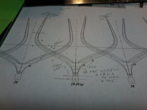
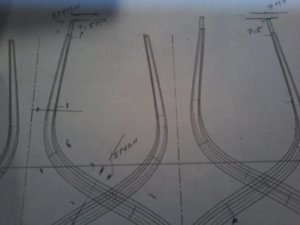
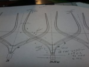
ok everyone, after a couple of days trying to get my mind to function and studying GILLES comments, going over the monograph again and reviewing GILLES SLIPWAY (gros venture) i think and i said think i have it figured out, showing pictures of aft frame No.29 with comments i do not think i can explain it with words so i wrote some comments on the frame plans hope this can get it across AS ALWAYS SUGFESTIONS CRITISISMS AND ANY COMMENTS GLADLY WELCOMED20200305_233455.jpg20200305_233649.jpg20200305_235050.jpg
 
i think and i said think i have it figured out, showing pictures of aft frame No.29

From your photo and comments on it, it looks like you have it right.
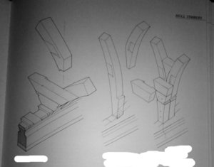
But just to show you so that you can confirm, 3 images attached.

First, drawings extracted from the "74-gun ship" by J.B.
It is a bit more complicated, but the basic layout is the same.

20200305_194852 a.jpg

A drawing from another monograph by the author of your monograph.
It is the same drawing shown a while back. I know this drawing is shown is in the text portion of several of Gérard`s monographs.
Chances are it is in Le Rochefort text portion as well.
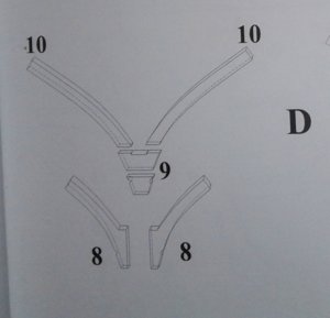
Exploded view:
Parts 8 are fitted in front of parts 9 and 10 (parts 9 and 10 would be closet to the stern)
Basically the same layout as your frame 29.

20200305_194914 a.jpg

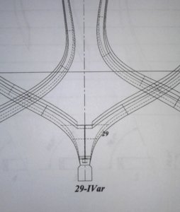
And here is Frame 29 (aft) of Rochefort
Knowing that:
solid line = edges & joints closest to viewer
dotted line = hidden edges & joints

20200305_195403 a.jpg

Regards.
G.
 
Hello Don, It sure looks like you have come a long way in a couple of months with Gilles help, keep up the good work. It may seam hard now but so very much depends on the work you do now for the finished results.
Regards Lawrence
 
In addition to the advice Christian gives above, I would suggest using a fine touch while sanding. Go easy with the material into the sander. It's not so much about the speed of the sander or the grit, but more about how much pressure you apply. You can also extend the life of you sanding paper by not sanding on the same spot every time. Hope this helps.
 
Back
Top