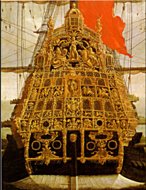
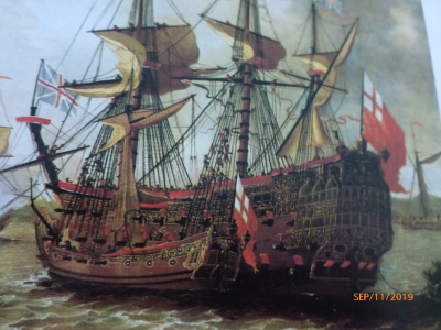
17th Century Ship Design and the Sovereign of the Seas (1637)

All this information is going right into my model, @CharlieT . That includes fixing a couple errors such as filling in the outermost gunports on the beakhead bulkhead. I mistakenly placed six gunports instead of 4, believing that the outermost ones were obstructed from view in the Payne engraving by the bulkhead decorations. The additional ports should be attributed to changes as part of the rebuild of 1658-1660. Your descriptions of the cheeks and the changes made during the rebuild were truly helpful!
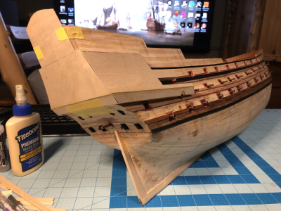
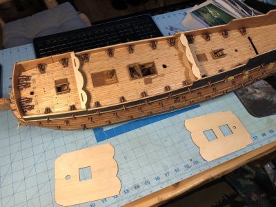
1418 Test Fit Forcastle & Halfdeck Bulkhead Jigs.jpg
 
Kurt, the street runs both ways. I've been following your excellent build, and will be stealing lifting purloining borrowing several ideas from you, too. I once again compliment you on your terrific decorations.
 
I did compare it with the Pett painting. It suggests an angle closer to 18 degrees. I chose 12 degrees because artistic perspective may have distorted the angle, and because the smaller angle puts the figurehead in a more favorable position with respect to the guns. Perhaps even more important is that the ship's trim would act to increase the angle, so the angle suggested by the Pett painting is likely too big. I do not know if the painting accurately portrays the trim, nor was I able to precisely estimate it on the painting. Nevertheless, one of the main reasons I called my choice as subjective was because the painting suggests a greater angle, so others may prefer it.
 
Last edited:

The Sheer Plan (continued)​

The Counter​

The Treatise tells us that “The counter pieces are certain small pieces of compass timbers, swept out by a circle and placed in the stern between the transom and gallery to support it in the overhanging of the stern, which is done by the help of the bracket in the side thereof.” The lower counter is an important part of how the ship looks. According to the Treatise’s it, like the head, “is but a matter of ornament, yet if proportion be not observed the whole work will be much disgraced by the uncomely winning of the ship.” Deane tells us that the counter “must rake so far aft as to hide the rudder head which comes just under it.” Bushnell does not mention the counter.

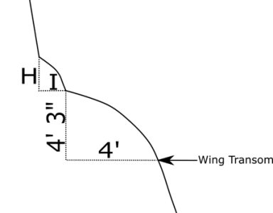
Shipwrights drew counters on their plans as part of a circle. Its radius varied among ships and shipwrights. The Newton Manuscript illustrates this. It allows for the counter’s sweep to be between ⅓ and ⅘ of the sternpost’s length. This ranges from about 9 feet 3 ½ inches to 22 feet 4 inches on the Sovereign.[1] The Treatise is more proscriptive. It suggests only one radius, 11/10 of the depth, and that the arc span a horizontal distance equal to half of this. Deane’s method (shown in Figure 61) is similar. He tells us to “set it by a square 4 feet aft, and by a perpendicular 4 feet 3 inches. When I have done, sweep it by a 7-foot sweep…” Figure 61 shows this, as well as an upper counter (labelled with “H” and “I”) These dimensions obviously require modification for the Sovereign, which is bigger than Deane’s ship, but Deane does not tell us how he obtained the lengths of his lines.[2]


Figure 61. Deane’s Description of the Upper and Lower Counters
1732899959427.png

Drawing adapted from Deane

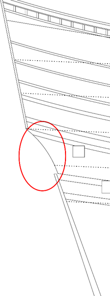
The current plans use a modification the Treatise’s method. Thus, a radius of 11/10 the depth, or 21.15 feet, is drawn from the post’s true head (but accounting for the rabbet’s width here) to the underside of the upper gun deck’s planking. Figure 62 shows the counter circled in red.

Figure 62 The Counter
1732899992911.png

This design ultimately causes all the weight of the upper stern to rest on the wing transom. This represents a weakness in seventeenth century ship design that persisted for quite some time. Because there is so much weight on this transom, it carries an “unduly heavy workload for a single timber.” (Lavery 1984, pg 34)

References​

Lavery, Brian. 1984. The Ship of the Line. Vols. Volume II: Design, Construction and Fittings. London: Conway Maritime Press.


[1] Assuming, of course, that its sternpost had the same dimensions as the post on the current plans.
[2] When expressed as a proportion of depth in hold, the sweep of Deane’s counter is less than half of the Treatise’s sweep. Deane tells us the depth of his ship is 15 feet 9 inches, so his counter’s sweep, which is 7 feet, is 44.44% of the depth.
 
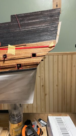
This is the stern profile on my model, as best interpreted from the Payne engraving. You can see the tiller protruding from the stern, since the rudder is not fitted yet. The curve of the counter will be partially occluded by the side galleries when they are installed.
1439 Transom Profile.jpg
 
Last edited:
That looks good!
By the way, the next section will be on the tiller and whipstaff, and the one after that will be on the galleries.
 
For clarity. The scupper holes were certainly lined with lead to minimise fungal attack. But the leather reference is for flaps cut from leather that hung down like a curtain over the holes. These acted as a simple one-way valve, minimising the amount of water that could enter into the ship, while presenting only a minor obstacle to water exiting the ship.
I have read in an 1850 source that the exterior leather flap was hinged at the bottom. So I am wondering what year this practice started? And, since museum models showing scuppers just look like a pipe sticking out of a round plate, where these leather flaps inside the scupper pipe? TYVM
 
For those who really want to know more about scuppers, I can add the following: they were also frequently made of leather. I have seen them listed among items in a ship's inventory.

A 1657 contract for scuppers states that those for a first rate were to be 28 inches long. They are shaped rather like a funnel, but wth both ends cut on a skew, to better suit the angle at which they met the waterways and the external planking. The inner, wide end was to be 18" breadth; presumably when it was laid flat. This would give a diameter when fitted of around 6". The outer, smallest end was to be 6", which would result in a diameter of around 2"; rather small. It is possible that the end of the scupper was intended to be crushed flat by the pressure of the sea against it, if the tube was empty; but that is speculation on my part. It is also possible that the flap was a separate part, added during installation, which being larger than the 2" specified here, would be much more visible.

The leather was to be 'liquored', presumably either tanned or varnished.

Ratty
Does anyone have any pictures of scuppers and leather scupper flaps? I understand what Bilge Ratt was describing, since a reducing cone made from leather would quickly seal when folded in half by wave action, but I'd be interested in seeing a variety of scupper sealing design, particularly for early ships.
 
Does anyone have any pictures of scuppers and leather scupper flaps? I understand what Bilge Ratt was describing, since a reducing cone made from leather would quickly seal when folded in half by wave action, but I'd be interested in seeing a variety of scupper sealing design, particularly for early ships.
Maarten's Royal Caroline build has something covering the scuppers...
 
On Dutch ships it was common to do this with a tube of sail cloth. The functioning is that if water protrudes from below into the scupper the sail cloth will fold and close the passage through the scupper.
This type of scupper seal is also drawn on the drawings of Richard Endsor, therefore I also used it for my Royal Caroline.
 
The Sheer Plan (continued)

The Tiller and Whipstaff​

The Sovereign was built before the invention of the ship’s wheel, so it was steered with a tiller and whipstaff. A whipstaff is a vertical pole that was attached to the tiller. The helmsman moved the whipstaff from side-to-side to move the tiller which, in turn, moved the rudder. The helmsman faced forward. The tiller rested on a horizontal wooden bar called the tiller sweep, which was sheathed in metal and coated with soap and grease to minimize the drag of the tiller as it rode across it. The whipstaff was connected to the tiller through a pivot point called the rowle.

We can approximate where the Sovereign’s whipstaff joined the tiller from the position of the 12th gun port on the middle gun deck. It appears to have been moved so the gun arming this port would not recoil into it (see “Gun Port Spacing”). The whipstaff likely ran from just under the middle gun deck to the upper gun deck. (Fox, Personal Communication) This made the Sovereign’s tiller and the whipstaff rather long. This is desirable. Both act like levers, and less force is required to move a longer lever than a shorter one. This harks back to Archimedes’ statement “Give me a lever long enough and a fulcrum on which to place it, and I shall move the world.” The difficulty is that when a ship becomes very large, it is impractical to make the tiller long enough. This likely encouraged the adoption of the wheel on larger vessels. (Reid 2016)


Figure 63 The Tiller and Whipstaff
1733409793184.png
Note: The figure portrays the deck’s height, and the thickness of its beams at the deck’s midline. The figure shows the space available for the tiller and whipstaff, and does not portray their actual thicknesses. Both could be thinner than the portrayed spaces. As on a real ship, there is little room for the tiller, so some may find it convenient to reduce the thickness of the middle gun deck’s beams beyond the 12 inches described in the previous section on the midship bend.

Steering by whipstaff presented a host of problems. Among them was that the range of movement of the rudder was limited. It may have been as small as five to ten degrees. (zu Mondfeld 1989, 148) Another was the whipstaff’s position dictated that the helmsman did not stand on a weather deck. Consequently, his field of view was limited and, on the Sovereign, he may not have been able to see outside at all. Orders to him probably had to be shouted down from a weather deck or brought down by runners. This must have made the Sovereign difficult to maneuver in conditions that demanded quick action The below-decks position of the whipstaff also meant that the helmsman could not see the horizon so he had to use a compass to steer a straight course. This is problematic because a compass’ response lags behind a course change. Finally, the helmsman also could not see the ship’s sails and, therefore, could not be given an order to sail by the wind while keeping the sails full. (Reid 2016)

Shipwrights often struggled to fit the tiller under the middle gun deck. They accomplished this in a variety of ways, some of which we have previously discussed. They might rotate the middle gun deck’s aft end up to create room. They make the lower gun deck slant down, which was advantageous because it kept the guns from recoiling “downhill.” (Fox, Personal Communication) The Pett painting suggests that neither of these two options was used on the Sovereign. Shipwrights also made room for the tiller by reducing the size and/or height of the chase gun ports above the lower gun deck. I have incorporated the latter on the present plans (see “Stern Chase Ports” for details. Finally, shipwrights sometimes made room for the tiller by reducing the size of the deck beams that were just above it. The present plans also use this maneuver (see “The Beams’ Thicknesses” for details).


References​

Fox, Frank. Personal Communication

—Personal Communication.

Reid, Phillip. 2016. "The Time Machine? Using Replica Analysis to Understand Merchant Ships and the Develmpment of the British Atlantic, 1600-1800." The Northern Mariner/Le marin du nord 26 (3): 299-316.

zu Mondfeld, Wolfram. 1989. Historic Ship Models. New York: Sterling Publishing Co,. Inc.
 
The Sheer Plan (continued)

The Quarter Galleries​

The Sovereign had upper and lower quarter galleries. Both galleries had an unroofed extension whet it was launched. This extension was used to handle the ship’s boats, though exactly how is unclear. (Fox)

The galleries are an important part of the ship’s appearance. Treatise’s author describes them, like the counter, as a “matter of ornament, yet if proportion be not observed, the whole work will be much disgraced by the uncomely winning of the ship.”

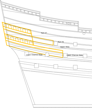
The Sovereign’s upper and lower galleries align with the wales and rails in specific ways. (Figure 64) The lower channel wale is at the lower gallery’s bottom and the upper wale is at its top. The upper wale and seventh rail similarly align with the bottom and top, respectively, of the upper gallery. Since the upper and lower quarter galleries are the same height, the distance between the lower channel and upper wales must equal the distance between the fifth wale and rail #7, and all three wales, as well as rail #7 must be parallel. Finally, the rails of the lower quarter galleries wrap around the stern, and these must be placed to align with the upper gun deck’s stern chase ports. This will be further discussed in the section on the stern. Additional details about these rails will also be provided in the next section.

The Treatise’s ship has one quarter gallery whose length is one sixth the length of the ship. [1] This works out to be 28 feet 10 inches on the Sovereign. The Sovereign’s galleries are longer. The lower quarter gallery is almost 35 feet long with its extension, and the upper quarter gallery is a bit less than 32 ½ feet long.[2]

The Sovereign’s quarter galleries, like those of other ships of its time, are set at an angle. Many models of this ship mistakenly portray them as horizontal. The Pett painting shows that the lower quarter gallery starts on the middle gun deck and ends on the upper gun deck. The associated stern windows serve the highest of these two decks. Similarly, the upper quarter gallery starts on the upper gun deck, and ends on the half deck, and its associated stern windows serve the latter deck. The Pett painting is not the only source to show that the galleries slope upwards as they move aft. The Payne engraving shows it, too. The Treatise tells us that the gallery’s should rise by one-fifth of their lengths. This is about how much the Sovereign’s galleries rise.

The galleries’ rises are not captured by a painting commonly used to model the Sovereign’s stern.[3] This painting, “Peter Pett and the Sovereign of the Seas” (which will be provided in the next section shows the galleries as horizontal. This is one of several errors in this painting (its other errors will be discussed in the next section).


Figure 64. The Quarter Galleries
1733515349008.png

Note: As previously discussed, the top of the middle gun deck’s second-from-aft port is comprised of an arch in the gallery floor. Accordingly, this port, which I previously drew as square, is now shown as arched. Note also that the galleries project aft of the plane of the upper stern. This mimics the Pett painting.


[1] The total length equals the rake of the post plus the length of the keel plus the rake of the stem. It is, 173 feet for the Sovereign.
[2] Lengths were measured on drawn plans and are, therefore, crude estimates. They are therefore rounded to the nearest half foot.
[3] The Greenwich Royal Museums attribute the painting to Peter Lely. (Greenwich Royal Museums ca. 1640-1645)

References​

Fox, Frank Personal Communication

Greenwich Royal Museums. ca. 1640-1645. Peter Pett and the Sovereign of the Seas. https://collections.rmg.co.uk/collections/objects/14422.html.
 
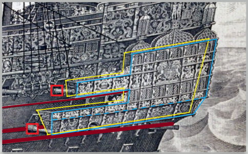
My analysis of the Payne engraving shows that the quarter galleries may not have extended beyond the transom, when taking into account the perspective of the galleries as shown below.
1733529376055.png

My first attempt at framing out the shape of the side galleries and how they interface with the stern is heavily influenced by how flat the rear ends of the galleries appear in the Painting of the stern attributed to Peter Lely. The painting does indeed have flaws, but there are elements that are rather faithful to the ship. The trick is choosing the correct ones. From what I can see, if the side galleries do jut out beyond the stern, they would be to the extent of the depth of the decorative carvings. Note in the Lely painting that the lower deck stern chase guns have a shadow above them which I attribute to the curvature of the counter. I may have to increase the angle of the side galleries to ensure that the door leading to the lower balcony from the middle gun deck is aligned with the floor of the balcony. It looks close now, but adjustments may be made before the final version of the galleries is established. @CharlieT , if you could describe the basis for having the side galleries extend beyond the counter, I'd be very interested.
1733529590070.png

1733529669869.png


1733529790109.png
 
Last edited:
Take a look at the Knyff painting (If you don't have it, no worries. I will show it in the next section). It clearly shows that the stern galleries curve outwards. You are absolutely correct in noting that the degree of curvature one incorporates will be influenced by the stern decorations. The wing transom's width (i.e., the narrowing of the breadth at the stern), and the degree of toptimber narrowing also play a role. On my plans, curving the stern galleries aft in a 2 foot arc seems to work. This may not work with a ship based on the Mantua kit.

Also notice that while the Knyff painting isn't perfectly clear, it suggests the side galleries project aft of the upper edge of the counter. This is consistent with the Pett painting.

My opinion, for whatever its worth, is that if you drew the yellow line you've layered on top of the Payne engraving through the centers of the tops of the aftmost upper and lower quarter gallery windows, you would come up with the something very much like Pett and Knyff show. The difficulty is that the bottom of this line will be a few inches aft of the stern that Payne shows. As you know, though, I am not convinced that Payne is always accurate, so this does not bother me all that much.
 
Jacob Knyff 1673
1733580124809.png


The painting shows a remarkable protrusion of the side galleries beyond the transom, if you concentrate your attention to the outline of the stern at the starboard side. Note that in other portions of the painting, the ship is heavily distorted. Interpreting old paintings involves careful cherry picking when it comes to selecting which features to incorporate into a model, and cross comparison with other sources.

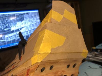
It would appear that moving the upper half of the transom forward on my model, cutting the wood at the pencil line at the top of the galleries shown in my photo above, would be the best way to change the shape of the stern in accordance with this new interpretation. Seeing as I had previously extended the transom rearward by 1cm, it will be a simple issue to break that wood extension out, saw the transom horizontally at the pencil line, and move the top portion of the transom forward to its original position. The hull framework is based largely on the DeAgostini kit which is the foundation of the model, albeit heavily modified. I must say that puzzling out the features of this famous ship has been quite an adventure.
 
Last edited:
Kurt,
I would like to comment "Interpreting old paintings involves careful cherry picking when it comes to selecting which features to incorporate into a model...."

You sentence very accurately describes what most modelers have done when reconstructing the Sovereign. This, I think, has caused problems. A more satisfactory approach is to decide with of the three profile views (Pett, Payne, or van de Velde) of this ship is correct, justify your choice, and then stick with it. This gets around the difficulties associated with cherry picking.
Choosing one of the three sources is problematic in that they all have inaccuracies, either due to the artist's lack of understanding of ship features, or filling in features in areas that were not actually witnessed by the the artist with estimations (such as the rigging arrangement in Payne's engraving). It makes choosing one source very difficult to support. Add to that the changes the ship went through in its career coupled with the time at which the source created the image, and we have quite a complex problem authenticating features on a ship like the Sovereign. It's a real minefield trying to figure out what the ship looked like at a particular time. When I described the process as cherry picking, I meant that each feature of the vessel could be taken from a different source if your first source has appears incorrect based on contemporary knowledge of that feature.

Take for example the Knyff drawing's galleries that we discussed recently. The extension of the galleries beyond the transom is not clear in Payne's engraving but is clearer in the Knyff painting. Since it is improbable that the entire stern's array of carvings were changed with a possible change to extend the galleries during one of the ship's rebuilds, one could conclude that the length of the galleries should follow the Knyff painting. Cherry picking is difficult to avoid.

As a beginner myself, I am faced with these choices for each and every feature of the model, having to sift through the sources to choose what to incorporate without the experience of being a lifetime 17th century maritime scholar. Instead, I gather information from others more knowledgeable in this topic than myself. You fall into that category, as did Frank Fox, (whose knowledge was not available to me). Some choices are obvious, such as aligning the windows on the side galleries to the stern windows when a course has them misaligned. Others require more in depth knowledge, research, and experience with the norms of construction of wooden ships for this time period.

This is the swamp we wade into when choosing to model ships from the 17th century. You guys who make models of HMS Victory have it so easy! :rolleyes:
 
Last edited:
Back
Top