-

Win a Free Custom Engraved Brass Coin!!!
As a way to introduce our brass coins to the community, we will raffle off a free coin during the month of August. Follow link ABOVE for instructions for entering.
-

PRE-ORDER SHIPS IN SCALE TODAY!
The beloved Ships in Scale Magazine is back and charting a new course for 2026!
Discover new skills, new techniques, and new inspirations in every issue.
NOTE THAT OUR FIRST ISSUE WILL BE JAN/FEB 2026
You are using an out of date browser. It may not display this or other websites correctly.
You should upgrade or use an alternative browser.
You should upgrade or use an alternative browser.
Artesania Latina Anatomy of Lord Nelson’s HMS Victory 1805
- Thread starter AlanOES
- Start date
- Watchers 39
-
- Tags
- artesania latina victory
AlanHey Alan,
Glad you said that. I'll keep your tip in mind. Your deck really looks like madness. Thanks for showing it. I am impressed.
Best regards
Günther
Thanks for the tips on the cannons and anchor rope. I received my kit and will be starting it this weekend. Hope mine turns out as good as yours . I will be watching and learning from your build log
Dave
Thank you Alan. Much appreciated. You would not believe it but I actually misplaced the container and after your message I realised that and went for a hunt for it! TonyHi Tony
All the wooden blocks are located in one of the clear plastic parts containers
I didn’t think much of the quality of the smallest single hole blocks, some didn’t have holes in them and I found I had to enlarge the holes to pass the thread through them even using a “Big Eye” needle
View attachment 538773
- Joined
- Dec 5, 2022
- Messages
- 1,119
- Points
- 443

Hey Toni,Vielen Dank, Alan. Vielen Dank. Du wirst es nicht glauben, aber ich habe den Behälter tatsächlich verlegt. Nach deiner Nachricht ist mir das aufgefallen und ich habe mich auf die Suche danach gemacht! Tony
where are your photos?
Cheers, Günther.

- Joined
- Nov 30, 2024
- Messages
- 156
- Points
- 103

Instructions video #24 completed
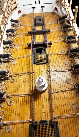
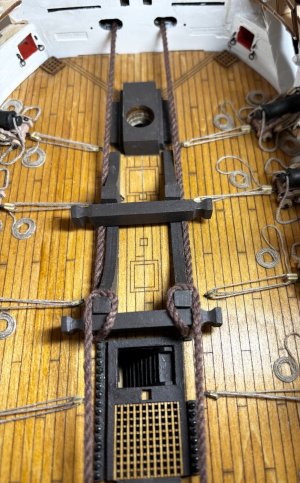
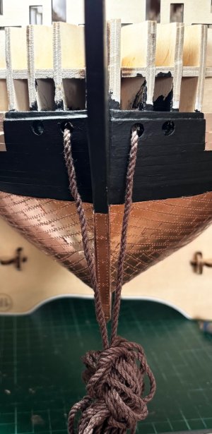
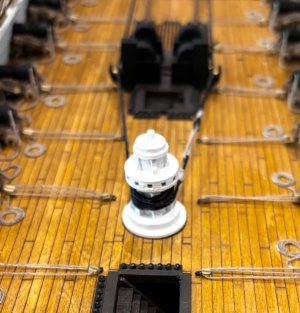
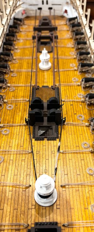
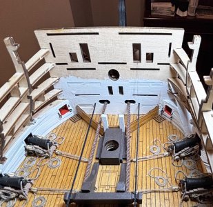
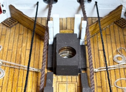
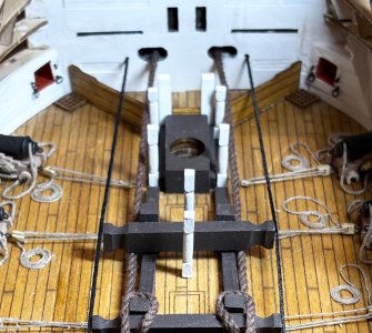
In this instalment I guide the anchor cables around the bits and out through the hawse holes in the bow
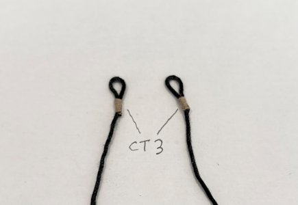
Construct the messenger cable and install it around the capstan and out through the pre drilled holes in the bow bulkhead (NOTE: In the video you are only instructed to harden the ends of the thread with CA glue to assist pushing them through the small holes,
I found that the way through was blocked by the wood pieces of the bow framework so had to drill though from the inside at a slight angle to make a route out for the threads)
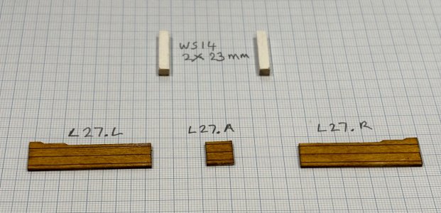
Next I stain and install the 3 boards that create the manger area at the bow.
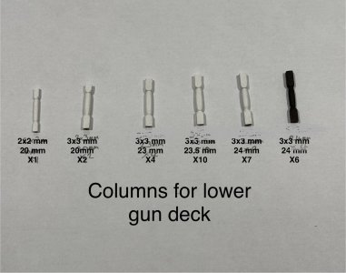
Next on to my mini lathe to turn 30 columns of varying heights and sizes to be placed on the lower gun deck.
Finally I bend some 0.5mm diameter brass rod as per the templates to form the bilge pump handles then insert them in position.
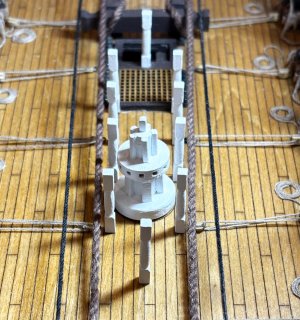
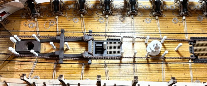
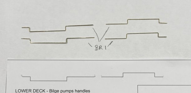
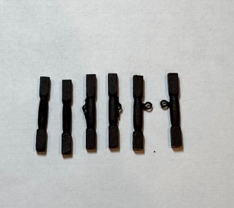
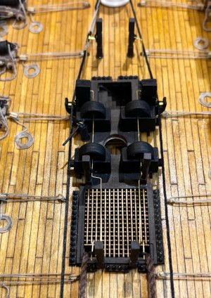
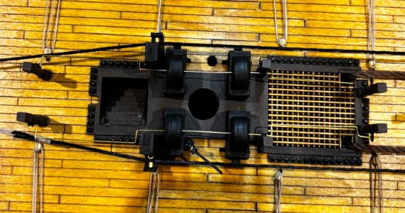
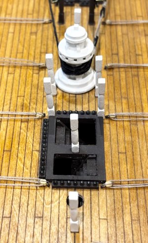
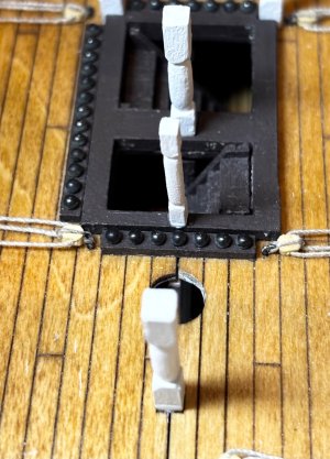


- Joined
- Nov 30, 2024
- Messages
- 156
- Points
- 103

Instructions video #25 Part 1
I have taken quite a few photos so far in this instalment so I’ve decided to split video 25 into 2 parts
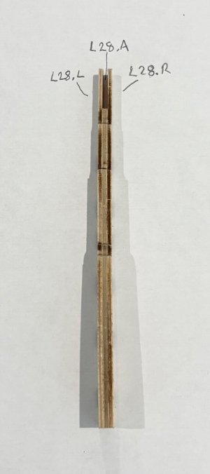
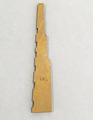
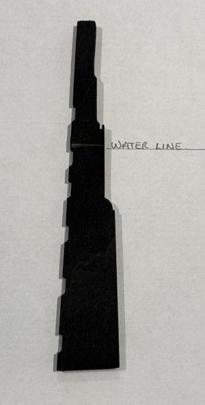
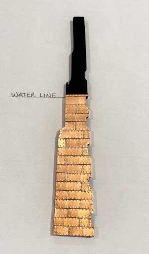
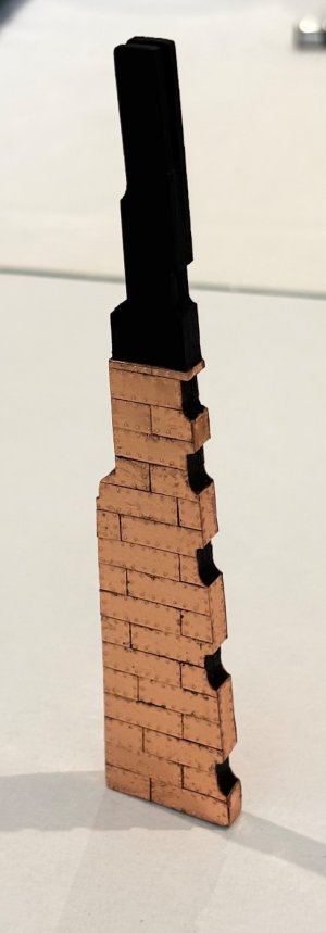
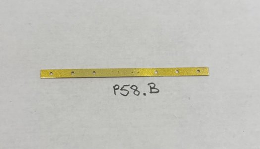
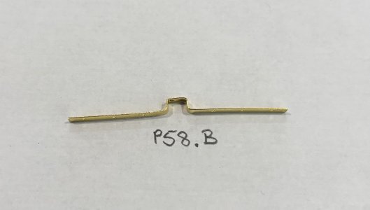
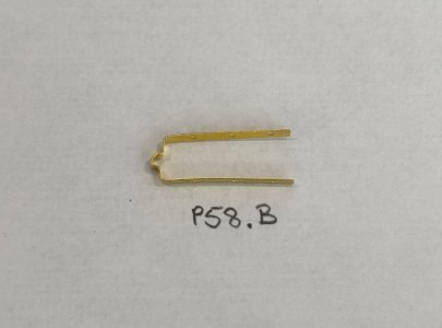
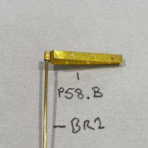
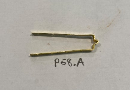
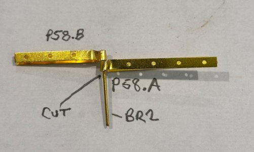
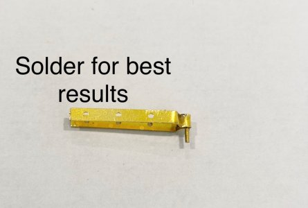
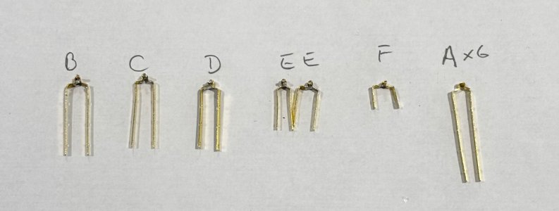
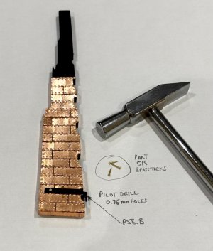
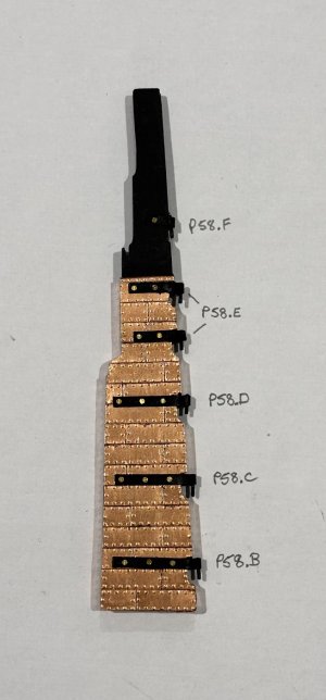
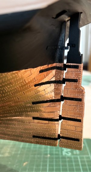
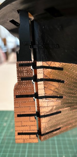
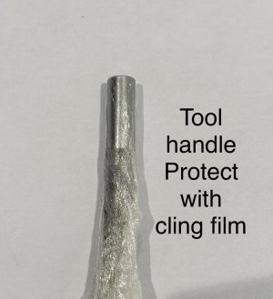
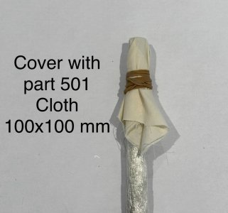
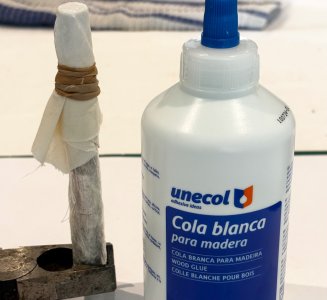
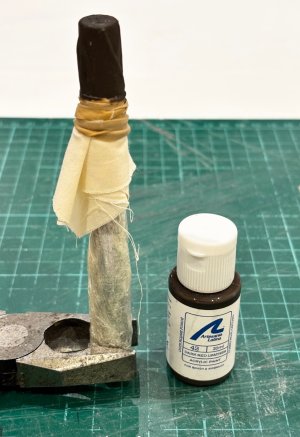
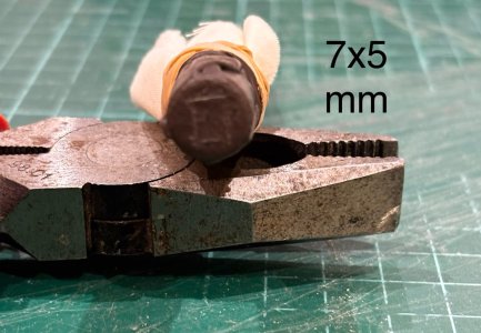
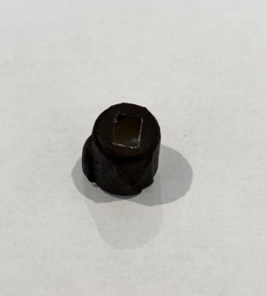
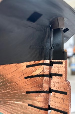
In this part I build the rudder and copper plate it. Make and shape the Gudgeons and Pintles, fit them in position and install the rudder in place.
Finally in this part I make and install the rudder’s gaiter. I was initially concerned that they did not included the spectacle plate at this stage, but fast forwarded several videos and see that it is included in the kit and is fitted at a later stage (video 50 I think) after attaching the chains to it.


- Joined
- Nov 30, 2024
- Messages
- 156
- Points
- 103

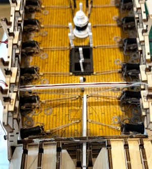
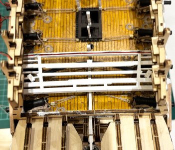
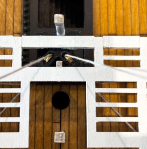
Instructions video #25 Completed
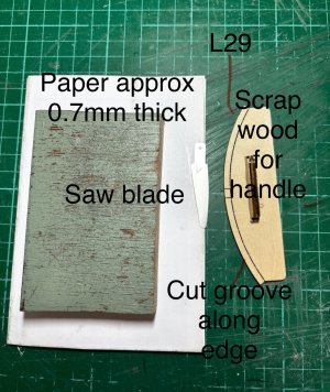
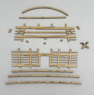
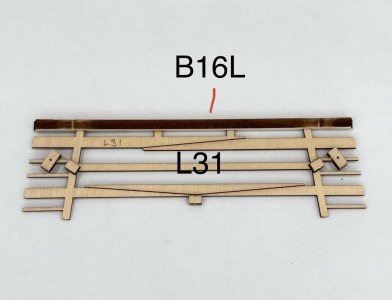
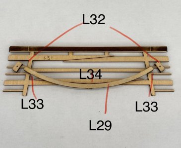
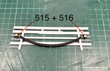
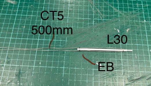
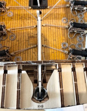
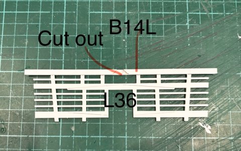
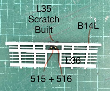
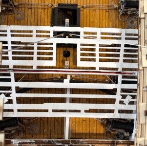
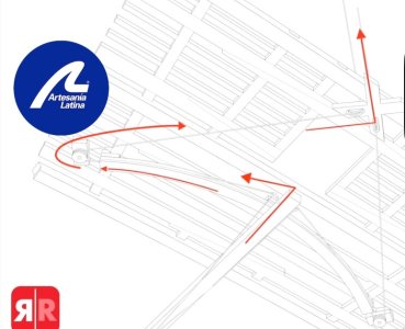
In this final part of video #25 I built the rudder steering gear. In the instructions it doesn’t tell you to glue the tiller (L30) into the slot in the top of the rudder, but I could see no reason not to, it also helps keep the tiller level when trying to pass the thread around the brass sheaves/blocks etc.
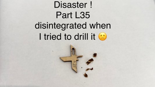
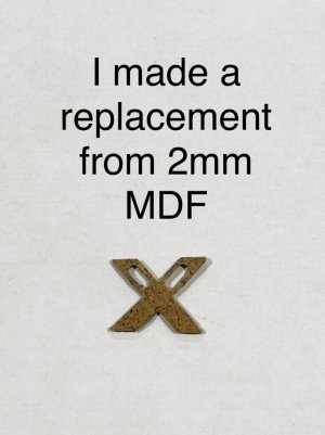
I had a disaster when trying to drill a hole in the edge of part L35, it basically disintegrated into many pieces!
I did email AL that evening and to there credit they replied next day to say they had shipped a replacement, but from experience of other deliveries from them I know it will take over a week to arrive, plus I was concerned that as it would be made from the same thin plywood, the same thing might happen, so I sourced some 2mm thick MDF and made my own replacement.
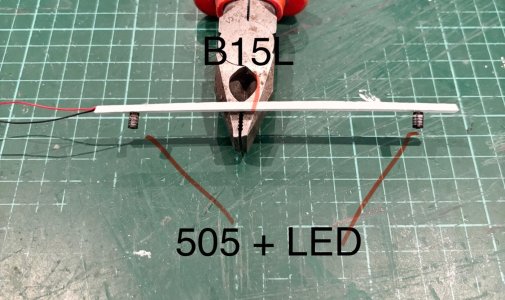
The rest was reasonably straight forward and hopefully the following photos will be self explanatory.


Last edited:
- Joined
- May 31, 2021
- Messages
- 86
- Points
- 88

Amazing! 


- Joined
- Nov 30, 2024
- Messages
- 156
- Points
- 103

2mmHope you don't mind my asking but what is the width of the pintles and gudgeons? Thank you very much. '
Allan
I noticed that there have been a few flags changing.The problem is Allan, kit makers have to be practical. Having a thinner strip of brass with several holes in it would make it more fragile and difficult to work with
ps. Have you changed your country ?
- Joined
- Nov 30, 2024
- Messages
- 156
- Points
- 103

Yes we changed to Italy for the past week and now France. Spain in a couple days. Can't hide anymore so going back to Florida on Friday. 
 LOVE the western Med!
Regarding the pintles and gudgeons, I have never had an issue with making them to scale using brass or copper. Drilling the 7 or 8 holes can be tricky but I do it after the parts are epoxied in place on the hull and rudder. A tiny dent with a pin or punch to make sure the drill bit does not wander should be done for each bolt location. Copper is softer and easier to work with and can be blackened after it is in place with a dab of diluted liver of sulfur.
Allan
Last edited:
- Joined
- Dec 5, 2022
- Messages
- 1,119
- Points
- 443

Hey Alan,
As always, a wonderful journey with you. I always look forward to seeing new pictures from you, especially as I will also be building the Victory from AL. That's why I'm taking on board all your experiences and will remember them.
Looks great as always.
Best regards
Günther
As always, a wonderful journey with you. I always look forward to seeing new pictures from you, especially as I will also be building the Victory from AL. That's why I'm taking on board all your experiences and will remember them.
Looks great as always.
Best regards
Günther

- Joined
- Nov 30, 2024
- Messages
- 156
- Points
- 103

I’m sure you can, and so could I probably if I really had to but kit manufacturers have to cater for all skill levels and to be honest, I’m happy with what is suppliedYes we changed to Italy for the past week and now France. Spain in a couple days. Can't hide anymore so going back to Florida on Friday.
LOVE the western Med!
Regarding the pintles and gudgeons, I have never had an issue with making them to scale using brass or copper. Drilling the 7 or 8 holes can be tricky but I do it after the parts are epoxied in place on the hull and rudder. A tiny dent with a pin or punch to make sure the drill bit does not wander should be done for each bolt location. Copper is softer and easier to work with and can be blackened after it is in place with a dab of diluted liver of sulfur.
Allan
Regards
Alan
I agree and this can be seen in that they make kits for various skill levels. But, this does not mean they have to supply the wrong parts such as out of scale hinges, incorrect cannon sizes and patterns, belaying pins on ships that never had any, and the list goes on. Thankfully, there are now a couple kit makers that are offering kits based on thorough research and using their research to manufacture a first class kit. This is a win win for them and for us.kit manufacturers have to cater for all skill levels
Allan
- Joined
- Nov 30, 2024
- Messages
- 156
- Points
- 103

Allan,I agree and this can be seen in that they make kits for various skill levels. But, this does not mean they have to supply the wrong parts such as out of scale hinges, incorrect cannon sizes and patterns, belaying pins on ships that never had any, and the list goes on. Thankfully, there are now a couple kit makers that are offering kits based on thorough research and using their research to manufacture a first class kit. This is a win win for them and for us.
Allan
It seems to me that all you’ve done from the start is to pick holes in this kit.
If you don’t like the kit or my build, my I respectfully suggest that you unfollow it
Alan


