Cool!
-

Win a Free Custom Engraved Brass Coin!!!
As a way to introduce our brass coins to the community, we will raffle off a free coin during the month of August. Follow link ABOVE for instructions for entering.
-

PRE-ORDER SHIPS IN SCALE TODAY!
The beloved Ships in Scale Magazine is back and charting a new course for 2026!
Discover new skills, new techniques, and new inspirations in every issue.
NOTE THAT OUR FIRST ISSUE WILL BE JAN/FEB 2026
- Home
- Forums
- Ships of Scale Group Builds and Projects
- Bluenose PoF Group Build
- Bluenose Group Build Logs
You are using an out of date browser. It may not display this or other websites correctly.
You should upgrade or use an alternative browser.
You should upgrade or use an alternative browser.
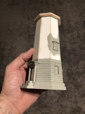
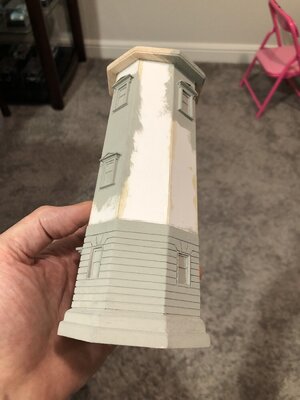
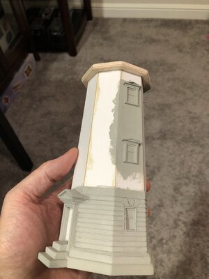
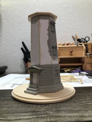
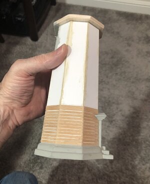
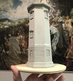
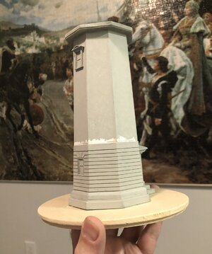
Looks like concrete and if not a second guess would be stucco which is made with portland cement which is just as good a protection as long as it has a good substrate mesh to help secure it from expansion/contraction with temp. changes. I like the implied quoines and keystone above the lower openings making a substantial base/foundation for the upper portion. RichThe lower windows…they are inset and need to be leveled (angle to wall).
View attachment 256975View attachment 256976
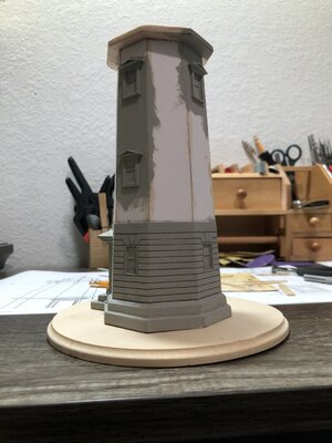
Then the boards to simulate the pattern on the lower tower and around the windows. It will be a lot of boards and a lot of work…but isn’t that how this goes…lol.
View attachment 256977View attachment 256978
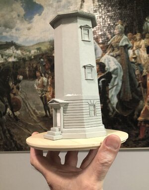
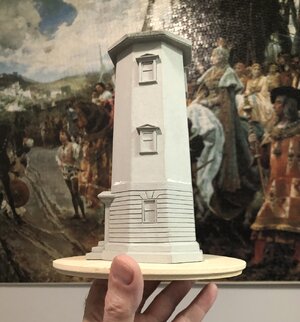
Then I painted to see what it’s going to look like. I am excited, once I start dry brushing the white on, it’s going to come alive. But that will be after I finish construction.
View attachment 256979View attachment 256980View attachment 256981
Pic for reference…
View attachment 256989
- Joined
- Oct 28, 2018
- Messages
- 760
- Points
- 403

Cool Dean
Thank you Henk. It’s actually a fun project! A lot of tedious work, but that’s model building.Cool Dean
When your tools are tweezers and an xacto knife, and you apply glue with a toothpick…you might be building a model…lol.
- Joined
- Jan 9, 2020
- Messages
- 10,566
- Points
- 938

Of course it's model building and I like it a lot. Apart from the beautiful work that you are doing, it does offer the kind of add-on to the build which I can appreciate. Even though it will add greatly to the overall visual appeal of the total picture, it remains a separate entity from the model. Both can be appreciated and enjoyed in their own right.
Thank you Heinrich! I think the truth is I wanted to build a lighthouse. And this was an excuse…lol.Of course it's model building and I like it a lot. Apart from the beautiful work that you are doing, it does offer the kind of add-on to the build which I can appreciate. Even though it will add greatly to the overall visual appeal of the total picture, it remains a separate entity from the model. Both can be appreciated and enjoyed in their own right.
But now that I am, I will hate to give it up, as I am growing very fond of it. But I suspect I will build more in the future.
You are making good progress with this build. The walls really come alive with the door, windows and beautiful vibrant base. I'm curious how you approach the skylight.
Regards, Peter
Regards, Peter
Thanks Peter! I still have to finish the boards around the base, then add a skirt or roof around the perimeter that will have a pitch, and below that is another piece of trim.You are making good progress with this build. The walls really come alive with the door, windows and beautiful vibrant base. I'm curious how you approach the skylight.
Regards, Peter
Then I have to do the corbels on each corner, 8 in total. Then I can paint and add the door in natural wood color.
Then finally I can start on the catwalk and upper lighthouse (the lantern room). So still a lot of work ahead. But, one piece at a time!
Last edited:
Thank you! No need to have a 3D printer! This is a complete scratch build, using plans I created!I really really like your work Dean. I was thinking about generating plans to make this completely from wood. I do not have a 3D printer.
Wonderful work. Thanks for posting this!
I started by finding an elevation view of the lighthouse, and with some known dimensions, determined the scale of it, and then used it to create a full scale model in 3D. Then I created a drawing (to 1/72 scale) using the model for views, that I printed on 11x17 to use as full scale plans to build with.
I have created it all out of wood thus far, except for the main lower base walls, that were made with construction board.
Last edited:
Someone asked me how I made all of the miter joints on the boards around the base of the lighthouse.
If I am using a miter saw, I usually have to get my angle finder and measure the included angle of the corner. In this case with an octagon, that would be 135 degrees. Divided by 2 and you get 67.5 degrees per board, therefore each board end would need to have 90 - 67.5 = 22.5 degrees removed, leaving 67.5 degrees each. That's in a perfect world, so the reason I use an angle finder is that each included angle will vary, some may be 136 degrees, 138 degrees, etc... and each time it is a different angle per board, per corner, that will result in a perfect miter joint.
But these being very thin boards (veneer) and on a model at a tiny scale, and finally me having to resort to doing it by hand, I chose the following method I will share with you.
First I glued on a board at the width of the side (the width changes as you move up or down being a tapered octagon!)

As shown above, this results in the board looking like it is too short to miter.

But I then file the end flush with the adjacent surface shown above.

Now I have the above shown corner.

Then I glue a board on that adjacent surface as shown above.

Now I file the end of that board flush with the adjacent board as shown above.

And finally I have a perfect miter joint as shown above with no gaps, regardless of the included angle!
Since it is going to be painted, and the boards are so thin (veneer) and small, this was the best approach in my opinion.
Try using a miter saw or measuring the angle on a 3mm x 1mm board...lol
If I am using a miter saw, I usually have to get my angle finder and measure the included angle of the corner. In this case with an octagon, that would be 135 degrees. Divided by 2 and you get 67.5 degrees per board, therefore each board end would need to have 90 - 67.5 = 22.5 degrees removed, leaving 67.5 degrees each. That's in a perfect world, so the reason I use an angle finder is that each included angle will vary, some may be 136 degrees, 138 degrees, etc... and each time it is a different angle per board, per corner, that will result in a perfect miter joint.
But these being very thin boards (veneer) and on a model at a tiny scale, and finally me having to resort to doing it by hand, I chose the following method I will share with you.
First I glued on a board at the width of the side (the width changes as you move up or down being a tapered octagon!)

As shown above, this results in the board looking like it is too short to miter.

But I then file the end flush with the adjacent surface shown above.

Now I have the above shown corner.

Then I glue a board on that adjacent surface as shown above.

Now I file the end of that board flush with the adjacent board as shown above.

And finally I have a perfect miter joint as shown above with no gaps, regardless of the included angle!
Since it is going to be painted, and the boards are so thin (veneer) and small, this was the best approach in my opinion.
Try using a miter saw or measuring the angle on a 3mm x 1mm board...lol
Last edited:
You have a true engineering command of the geometry and math for this "carptentery" Well done!Someone asked me how I made all of the miter joints on the boards around the base of the lighthouse.
If I am using a miter saw, I usually have to get my angle finder and measure the included angle of the corner. In this case with an octagon, that would be 135 degrees. Divided by 2 and you get 67.5 degrees per board, therefore each board end would need to have 90 - 67.5 = 22.5 degrees removed, leaving 67.5 degrees each. That's in a perfect world, so the reason I use an angle finder is that each included angle will vary, some may be 136 degrees, 138 degrees, etc... and each time it is a different angle per board, per corner, that will result in a perfect miter joint.
But these being very thin boards (veneer) and on a model at a tiny scale, and finally me having to resort doing it by hand, I chose the following method I will share with you.
First I glued on a board at the width of the side (the width changes as you move up or down being a tapered octagon!)
View attachment 257445
As shown above, this results in the board looking like it is too short to miter.
View attachment 257446
But I then file the end flush with the adjacent surface shown above.
View attachment 257447
Now I have the above shown corner.
View attachment 257448
Then I glue a board on that adjacent surface as shown above.
View attachment 257449
Now I file the end of that board flush with the adjacent board as shown above.
View attachment 257451
And finally I have a perfect miter joint as shown above with no gaps, regardless of the included angle!
Since it is going to be painted, and the boards are so thin (veneer) and small, this was the best approach in my opinion.
Try using a miter saw or measuring the angle on a 3mm x 1mm board...lol
 Rich
RichThank you Rich, the above method requires no math, no miter saw and no angle finder.You have a true engineering command of the geometry and math for this "carptentery" Well done!Rich
It is merely an analytic approach to solving a difficulty with miter joints on veneer.
So, it looks like the A-team was also here, Dean.Someone asked me how I made all of the miter joints on the boards around the base of the lighthouse.
If I am using a miter saw, I usually have to get my angle finder and measure the included angle of the corner. In this case with an octagon, that would be 135 degrees. Divided by 2 and you get 67.5 degrees per board, therefore each board end would need to have 90 - 67.5 = 22.5 degrees removed, leaving 67.5 degrees each. That's in a perfect world, so the reason I use an angle finder is that each included angle will vary, some may be 136 degrees, 138 degrees, etc... and each time it is a different angle per board, per corner, that will result in a perfect miter joint.
But these being very thin boards (veneer) and on a model at a tiny scale, and finally me having to resort to doing it by hand, I chose the following method I will share with you.
First I glued on a board at the width of the side (the width changes as you move up or down being a tapered octagon!)
View attachment 257445
As shown above, this results in the board looking like it is too short to miter.
View attachment 257446
But I then file the end flush with the adjacent surface shown above.
View attachment 257447
Now I have the above shown corner.
View attachment 257448
Then I glue a board on that adjacent surface as shown above.
View attachment 257449
Now I file the end of that board flush with the adjacent board as shown above.
View attachment 257451
And finally I have a perfect miter joint as shown above with no gaps, regardless of the included angle!
Since it is going to be painted, and the boards are so thin (veneer) and small, this was the best approach in my opinion.
Try using a miter saw or measuring the angle on a 3mm x 1mm board...lol
‘I love it when a Plan comes Together’.
Good consideration in advance, saves work and gives a nice result.
And your ‘degree-reasoning’ reminded me of my math lessons from early on. My favorite subject at school.
Regards, Peter
Math is why I ended up being an orthodontist (no math needed)So, it looks like the A-team was also here, Dean.
‘I love it when a Plan comes Together’.
Good consideration in advance, saves work and gives a nice result.
And your ‘degree-reasoning’ reminded me of my math lessons from early on. My favorite subject at school.
Regards, Peter
 . But I am pretty good at visualizing things in 3D so I, too, can appreciate Dean's approach.
Thanks guys, one important fact that I failed to mention is that it is actually a compound miter joint, due to the fact the walls are at a 5 degree angle that tapers upwards. So this is a easy way to get both angles by filing the overhang of the board with the adjacent surface. Otherwise it becomes a very time consuming and tricky corner!  And this method will work with any thickness board.
Never liked the math (and still), that's probably why I didn't end up an orthodontist (even no math needed)Math is why I ended up being an orthodontist (no math needed). But I am pretty good at visualizing things in 3D so I, too, can appreciate Dean's approach.


