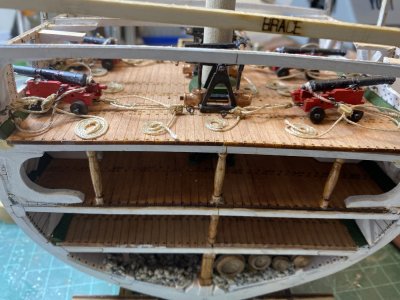
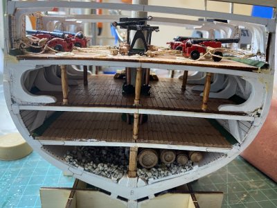
Constitution Cross Section MS20245 Model Expo

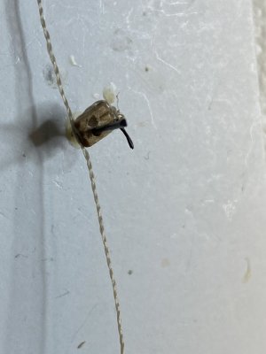
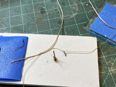
Next up is the gun tackle for the cannons. Three sets will be needed for each cannon 2 gun tackles that would haul the cannon into firing position and change its aiming point and a train tackle that would be used to pull the cannon back into the ship. For this 12 sets of blocks would be used, 12 single and 12 double. I started by enlarging the holes in the blocks so the line would actual pass through it. Using a drill vise i gently enlarged the holes and made sure they were free of any obstructions. some blocks needed small hooks seized to them. Some needed a hook and a line seized on opposite ends. I started by using the small thread I was using for seizing the other lines and tied a small hook onto it. I placed a small piece of wire onto some foam board to hold the block as I tied onto it. A nearby piece of doubled up tape was helpful in holding loose ends of line that seemed to want to fly away on it's own. for the block that required a line seized onto it, I also tucked a length of line to the seizing thread.
IMG_9788.jpeg

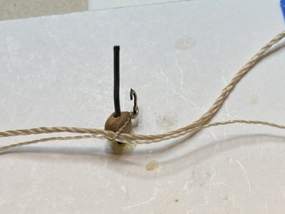
The line was then positioned and tied tightly using a square knot.
IMG_9789.jpeg

After this I help the hook with a clamp and seized the line with the same length of line I used to seize the hook onto the block.

IMG_9791.jpeg

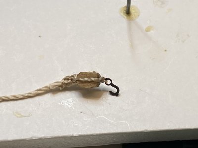
I used 5 or 6 half hitches around the line and then placed a drop of glue on the seized area. After it dried I cut off the excess lines.
IMG_9792.jpeg
 
After stropping several blocks with small hooks I had a lot of trouble aligning the stropping line along the block before I tightened them up. I finally put a dab of glue (I used the wood glue but the CA would also work) onto the block where I wanted the hook to be and aligned and stuck the stropping line with the hook onto that spot. After allowing the glue to dry a bit I found it much easier to align the stropping line on the block.
IMG_9799.jpeg

I then assembled my first Train tackle using one single and one double block.
IMG_9802.jpeg
 
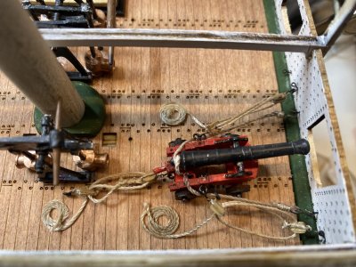
I set up a few tackles and tried them on my "stage" set just to get an idea of what I have to do. My first discovery is that I can really use about half as much line as I have used for the tackles. I am slowly tightening the tackle to get a realistic look of how the lines would look.

IMG_9804.jpeg
 
After doing most of this work I came across a wonderful you tube video by Olha Batchvarov showing how she does this work in a much more elegant way!


I strongly suggest you watch how she produces the cannon tackle!
 
While I was making the gun tackles I decided to glue the walls of the gun deck to the frame. The required a lot more sanding of the tabs to fit into the frame. I do not know if the height of the waterways is more than they wanted. but the walls fit nicely once everything was sanded.
IMG_9812.jpegIMG_9813.jpeg
 
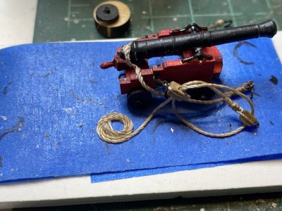
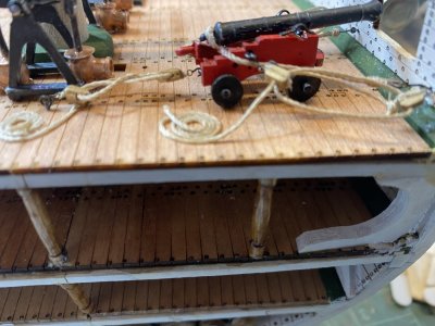
To form the rope coils on the tackle, I borrowed the method that Olha Batchvarov used in her you tube video. She placed the line down on a sticky tape surfeace and used a round form to get the coil. I used a pare cannon wheel, as I did not want the coil to be too large. I figured the crew on a ship would want to keep the amount of line to a minimum, since space was tight. I carefully placed the line around the form pressing it down to stick into place. I then took the wheel off and coiled the rest of the line inside the other line. The procedure went quite easily. One could just as easily wind the line outside the first coil if you wanted a larger coil.
IMG_9816.jpegIMG_9819.jpeg
 
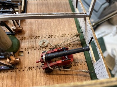
To put on the planking, these cannons will be turned upside down and on their side, so I wanted to make sure they were firmly attached. To help with this I drilled a hole in the carriage frame of the cannons. I then set the cannon into place attached to the frame with the breeching line. When I was happy with the position I drilled a hole into the deck going through the hole in the gun carriage. I am luck enough to have a long 20 gauge spinal needle that was able to easily go through the deck. I then used a eyebolt that I coated with wood glue and placed through both holes. I also used a dab of wood glue under the wheels. With things in place it is very hard to see the eyebolt securing the cannon.

IMG_9820.jpeg

Then using tweezers I attached the 3 gun tackles, gluing the coils to the deck and using a drop of CA to help secure the hooks onto the eyebolts.
IMG_9821.jpegIMG_9822.jpeg
 
I altered the location of the eyebolt for the train tackle, as there was not enough area for a pleasing effect. Of course, once the spar deck is added a lot of this detail will be hard to discern.

IMG_9824.jpegIMG_9826.jpeg

After everything dried I turned the ship over and nothing budged. Well three more cannons to go!
 
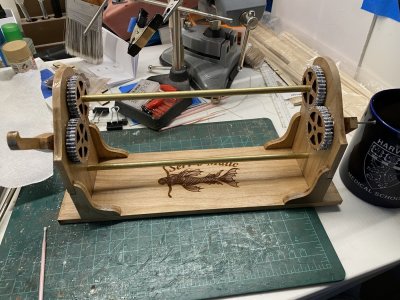
While doing my build, I decided to get a serving machine to serve the longer lines. I found the serving machine from Syren.

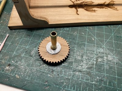
It has gotten mixed reviews but I decided to order it. It came as laser cut maple parts and a few brass tubes. The assembly instructions are only available online. I sanded the char off the parts as suggested and it was easy to assemble.
IMG_9828.jpeg

I then put on a few coats of poly acrylic to seal it. To make sure that it operated smoothly, I used lithium grease on all the moving surfaces and bearing points.
IMG_9831.jpegIMG_9832.jpeg

Once assembled it appear to rotate easily with no slippage.
IMG_9833.jpeg

I will follow up with how it works, or doesn't when I gain some experience with it.
 
Last edited:
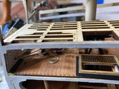
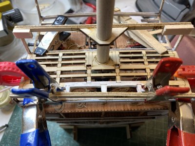
While waiting for things to set into place with my second cannon, I decided to test fit the spar deck framing that goes above the gun deck. When I did this I ran into a potential problem. The side edges of the decking stand proud to the frames by about 1/16th of an inch.

IMG_9839.jpeg

IMG_9838.jpeg

I realize this is due to the walls of the gun deck protruding up. If you remember I had to make the notches for the walls deeper to fit into the framing. I do not understand why this occurred. Others in previous build logs did not report this problem. Both waterways that the side walls stand on are the proper size and both rest on the framing below not on the decking. My main concern is that the outer walls will not align with the inner wall gun ports. But we will fix that when it becomes necessary. I was thinking of using my block plane to plane the surface on the edges of the spar deck framing down, but I decided it was just easier to sand them.
IMG_9842.jpeg

Doing it slowly it did not take much time to get the edges down to a level that was acceptable.
IMG_9841.jpeg
 
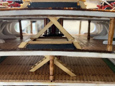
While waiting for things to dry on the other side I started to put in the standing and diagonal knees into place. They actually went into place very easily.
IMG_9846.jpegIMG_9847.jpeg

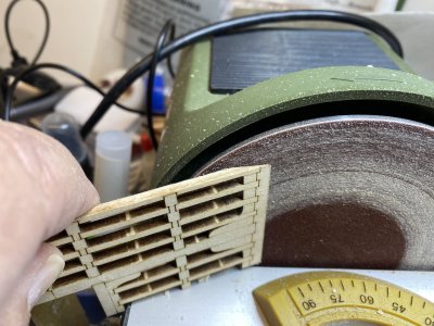
The top side diagonal brace that fit against the spar deck framing was beveled to fit more closely using a disk sander. The bottom portions also had to be trimmed and angled to fit against the standing braces.

IMG_9848.jpeg

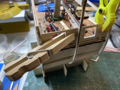
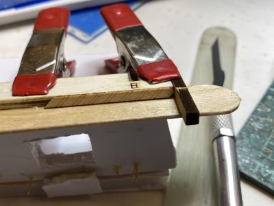
Some of the braces I was unable to clamp using my regular clamps. As I have stated in other building logs I have used clothes pins which I 'Flipped over" to make longer more controllable clamps. These worked well here.

IMG_9849.jpeg
 
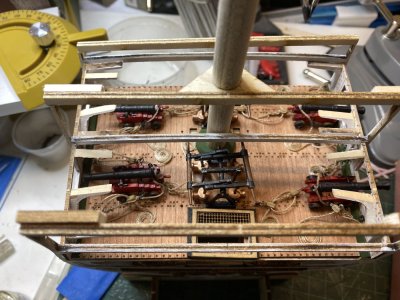
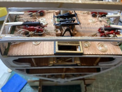
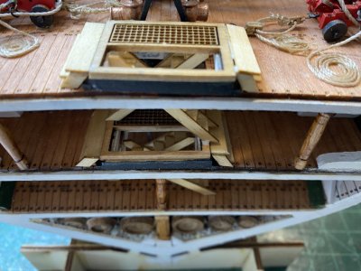
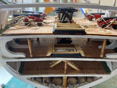
Well the gun deck is finally complete. I now need to place stairs between the berthing and gun decks then I will place the spar deck framing in place. I have not yes decided whether to cover all the spar deck with decking or to expose part of it so people can get a better look at the gun deck.

IMG_9852.jpegIMG_9853.jpegIMG_9854.jpegIMG_9857.jpegIMG_9858.jpeg
 
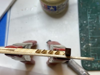
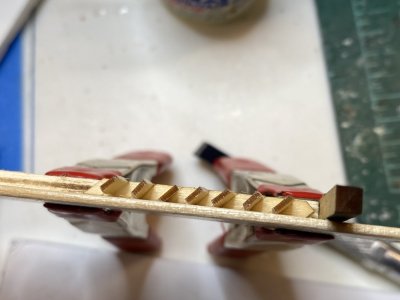
Building the ladders between the berthing and gun deck, I was unhappy with the method I used before, placing the rungs one by one against the risers. The rungs kept shifting because of gravity.

IMG_9859.jpeg
So what I decided to do is to shift the jig so it the risers were on their backs so to speak and to lower the rungs onto the risers.
IMG_9860.jpeg
IMG_9862.jpeg

I found this method much easier to do. I then glued the top riser to the rungs and clamped them until the glue dried.
IMG_9863.jpeg
 
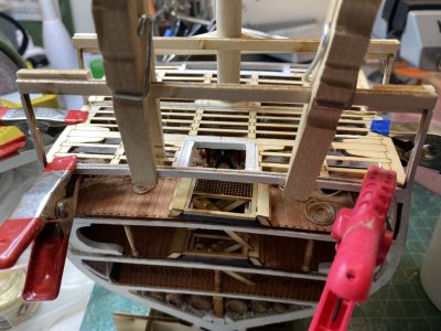
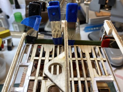
When I was putting the spar deck framing on it would not fit. The problem was that the knees should have been level with the bottom of the ship frames and I made them level with the top. Instead of redoing all the knees I decided to shave down the area of the spar deck framing where the knees go. To do this I used a new toy I got, a "nail drill" used for manicuring nails. It is almost like a miniature Dremel, except is is very light weight. The best part is that is was $10 on Amazon. It works very well as a small drum sander, especially for curved pieces. For those who are interested in it be aware that the shafts are not interchangeable with the Dremel (Dremel shafts are bigger), and it does not have the torque a Dremel does. However it is very lightweight and fits well in your hand and powerful enough to do what you want.
IMG_9869.jpeg

After some fiddling around I got the Spar deck framing to fit into place.

IMG_9872.jpeg
 
I set up a few tackles and tried them on my "stage" set just to get an idea of what I have to do. My first discovery is that I can really use about half as much line as I have used for the tackles. I am slowly tightening the tackle to get a realistic look of how the lines would look.

View attachment 509975
I know this is a test simulator, but I believe your blocks are reversed and the double block attaches to the hull, and you pull back, the way shown would not work for providing best leverage on pulling of the ropes.
 
Back
Top