Donnie's HMS Blandford Cross Section Build: 1/32 Scale [COMPLETED BUILD]

Thank you Kurt and Uwe, et al.
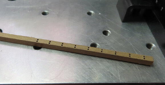
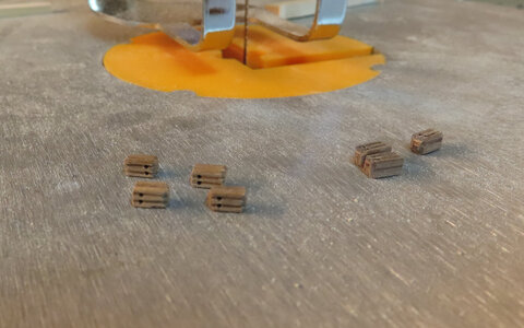
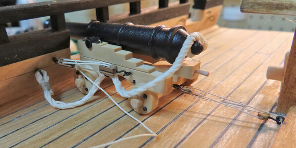
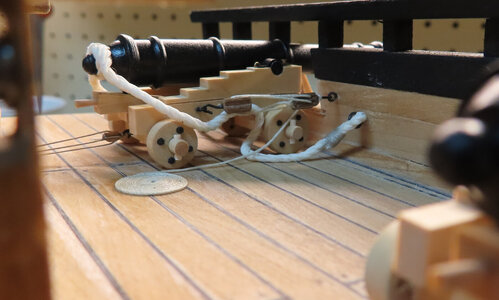
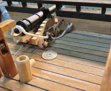
Now, to prepare the ring bolts and other hardware for the final rigging, including having to make my own blocks. I still have not found a breeching line that I am happy with. I just used a tiny file to make the grooves on the blocks. Sorry that I did not include photos of that whole step by step. Kind of hard holding the camera and doing that at the same time.
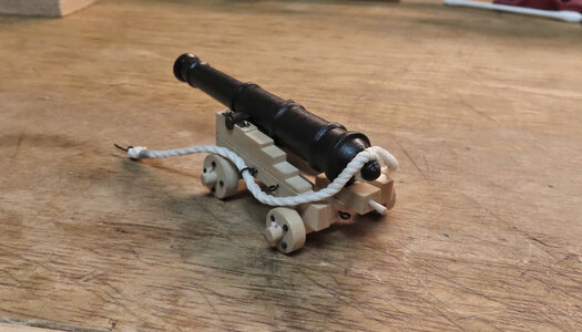
Also, I finally added the chock for the wheels and trimmed off axles.
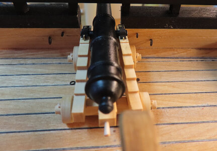
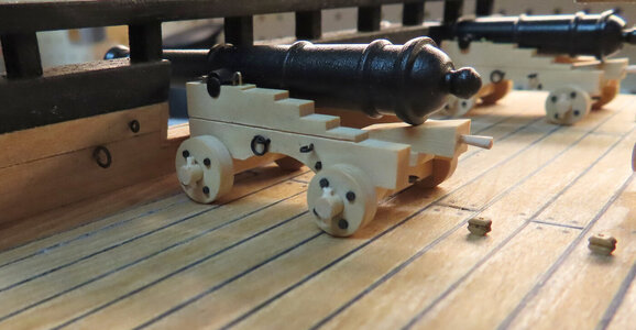
carriage-50.jpg

carriage-51.jpg

carriage-52.jpg

carriage-53.jpg

carriage-54.jpg

 
Thank you Dave !
onto more rigging. Finally got some breeching line that I like. I got it from Hobby Lobby. Part #123588 1.2mm thick. Natural Cord.
I researched many pictures of this and what I found was more of a thicker rope type for the breech. Then making the other rigging blocks, lines for the rest of cannon rigging.
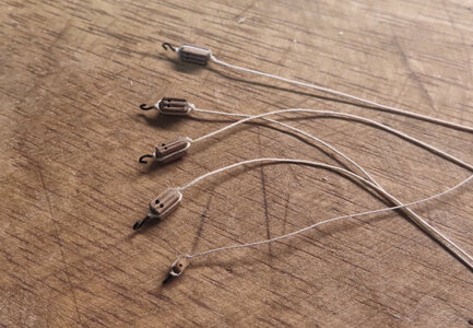
The larger pulleys are for the Gun Tackle and the smallest Pulleys (which I have more to make) is for the Train Tackle (at least that is what the books say).
The rigging line for the larger blocks is a Hobby Lobby H.H. Lizbeth Size 20 Col 603

carriage-55.jpg

carriage-56.jpg
 
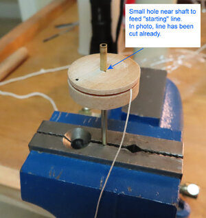
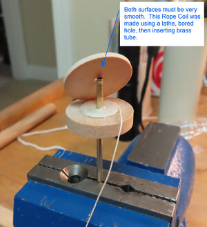
This next step was and is a very tedious process of which I was not looking forward to. First I had to make some type of Rope Coil making thing. (not sure if it has a proper name). Taking from ideas toss around, it was time to head to the lathe with about a 1 inch dowel. Made sure that the dowel was 'faced' nice and smooth, then bored a hole to accept a brass rod. Then I parted off the 'top' - all of which was no measuring, just going with it.
Both surfaces must be really smooth like glass for the line to wrap around, as it can not 'hang' on any burr or anything. You can use wax if you wish, but it must be very smooth (as what I found out).
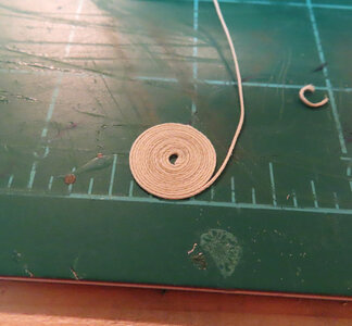
Then I made a small hole for the TOP part right at the edge of the shaft. This is where you feed your starting line into that adds tension as you wrap the line. It took a few tries to get the hang of it. Surprised me that it worked as well as it did. I then coated the coil, with 50/50 water and white glue. Nothing is holding the 'top' down as you just use your hands and fingers to hold the contraption in place as you wind the coil VERY carefully. I will divulge a secret. The coil is spliced onto the rest of the rigging to make it look like it is all one long line.

carriage-58.jpg

carriage-59.jpg

carriage-60.jpg

carriage-61.jpg

carriage-62.jpg
 
Hello Donnie, You are the master and chief for using your power tools. I can see you are truly enjoying the lathe and mill. As a result, we can see very fine work! Thumbs-Up
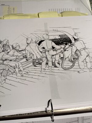
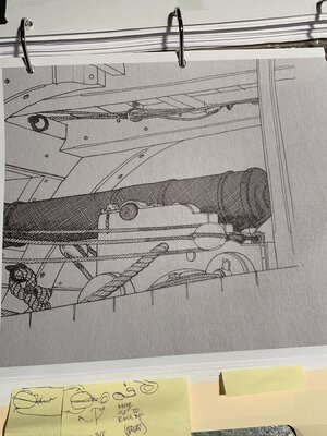
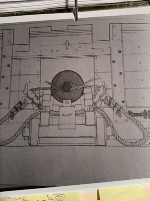
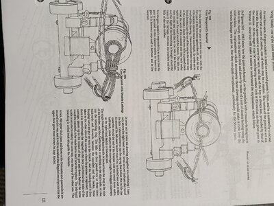
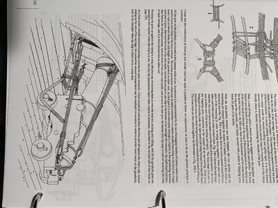
Very nice coil jig that you made/used. Also nicely done gun carriages and tackle. Jean B. shows a few different manners of placing the restraining hawser at the cascabel. There was also the often seen passage of the hawser though holes in the carriage under the barrel. That is the way that I have it in my firing cannon carriage. Here are some of J. B's from his 84 French gunship. First the gun crew:Carriage Restraining Hawser.jpg
Now a side elevationCarriage side view.jpg
Next a breach end viewBreach End view.jpg
Now on to a cascabel lashing for temporary restraint:Temporary breach securement.jpg
And securing the gun while underway to prevent any motion. The option was to lash it parallel to the side but that took a lot more effort and different configuration while providing more working deck space.Temporary securemenet lashings and view.jpg
Ultimately it all depends upon the gun manufacture and the carriage used for the particular ship and era. Just some thoughts. PT-2 (Rich)
 
Thank you Jim, and I take that with a lot of humility. There are other methods actually of making the rope coils that are quite ingenious. I guess I get in a hurry and rush through things wanting to put this project to rest -- LOL

Thank you PT-2,
this was the type of info I was looking for before I started, but humm - too late, I have to stick with what I have. I have the AOTS Blandford Book and was trying to follow exactly what the drawings had there.
The drawings from J.B.s 84 gun French ship so there are likely different manners with other countries and ages. You will produce an excellent build when done, I am sure. PT-2 (Rich)
 
Or with a perpendicular or lead, like I do it normally - If you have one, it is in my opinion that fastest and most accurate possibility
View attachment 127491
Looks like a small plumb bob and line are being used for alignment. . . imagine that, one of the oldest tools in existence for building is still being employed by us today at a vast range of scales. Old levels used a triangular frame with a plumb-bob and line for perpendiculars before they melded that into an upside down T with the plumb line at the top center where the out of horizontal T legs would cause the plumbline to swerve off of vertical. Some things don't change that much. PLumb lines are much more accurate than arced bubble levels. Just a reflection. PT-2
 
Looks like a small plumb bob and line are being used for alignment. . . imagine that, one of the oldest tools in existence for building is still being employed by us today at a vast range of scales. Old levels used a triangular frame with a plumb-bob and line for perpendiculars before they melded that into an upside down T with the plumb line at the top center where the out of horizontal T legs would cause the plumbline to swerve off of vertical. Some things don't change that much. PLumb lines are much more accurate than arced bubble levels. Just a reflection. PT-2

True enough...but a plumb line does not define a perpendicular unless the plane it’s intersecting is perfectly horizontal. Another measurement needed!
 
True enough...but a plumb line does not define a perpendicular unless the plane it’s intersecting is perfectly horizontal. Another measurement needed!
I believe that if the plumbline is centered on either of the old Egyptian triangular leg device( (upside down V shape which is the horizontal part) or on the center of the upside down T shape legs on the bottom, then the horizontal is proven. If either are off of the center then those base legs' points were not horizontal so that type of device served in testing both the horizontal and vertical perpendicular. Another old tool was used in testing perpendiculars (verticals) with a wooden piece with parallel sides to a centered plumbline/bob would prove perpendiculars or the vertical face of a member of element like a wall or post. The plumb line/bob is still the active working part of all of these old instruments. Interesting to consider isn't it.
 
Thank you Kurt and Uwe, et al.
Now, to prepare the ring bolts and other hardware for the final rigging, including having to make my own blocks. I still have not found a breeching line that I am happy with. I just used a tiny file to make the grooves on the blocks. Sorry that I did not include photos of that whole step by step. Kind of hard holding the camera and doing that at the same time.
Also, I finally added the chock for the wheels and trimmed off axles.
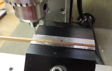
View attachment 188537

View attachment 188538

View attachment 188539

View attachment 188540

View attachment 188541

Nice looking carriages! PT-2
 
PT. I think I am going to pass on that. I am lacking the materials to do so, plus honestly just ready to put this project to rest. I agree, it would really make things look better though.
 
PT. I think I am going to pass on that. I am lacking the materials to do so, plus honestly just ready to put this project to rest. I agree, it would really make things look better though.
I fully understand. Any additional carriage bolts would be microscopic and lost in most viewing of the build. I am sure that it will be well appreciated when done. PT-2
 
I am finding that my Coil Making Jib is becoming a pain in the ACE. (if you know what I mean). I have already thought out some other designs I might have to try. One is using all aluminum and a much thicker dowel to hold the blasted thing. I was in a hurry as usual trying to come up with an idea. I saw where someone used a compression spring to keep the two pieces pushed in while you wrap the line. This could turn (no pun intended) into a major ordeal of which I am almost finished making the coils anyways.
I have found the ONLY way to make the coils "stay" in place is to coat the line with beeswax. Using 50/50 water/glue just does not work for me. Then once the coil is exposed on the wheel, then mop it down with the 50/50. Then let it dry and remove from spindle or wheel.
 
Back
Top