HMS Blandford 1:48 POF Modelship Dockyard [COMPLETED BUILD]

Hello and again thank you all for you for being here. Today I promised that I would show you how I removed the char from my ribs, this is no magic bullet but it works quite well for me.

Instead of using a small Dremel type sanding drum at high speed I tried using a large sanding drum at low speed. I used a fine/medium grit drum, about two inches in diameter in a low powered drill, I set the speed to just a little faster than an electric screwdriver and used that, I found that the larger drum better fit the curve of the rib, at this slow speed it was less aggressive and removed the char more slowly so was more controllable, yet it was quicker because more area was sanded by the larger drum at any time and best of all because of the low speed the char dust wasn’t thrown up into the air like with a high speed Dremel but it just fell to the bench like it does when hand sanding. I only sanded the rib part that was clamped in the vice, moving it around regularly so had no breakage issues. I know we all have are preferred methods of doing things but this worked for me and is worth a thought.

The rib production line is working well and acceptable progress is being made with no problems so far.


View attachment 395721

View attachment 395722

View attachment 395723

View attachment 395724

View attachment 395725

View attachment 395726
What a pace, Ken. A nice progress of fine looking frames.
Regards, Peter
 
Hello and again thank you all for you for being here. Today I promised that I would show you how I removed the char from my ribs, this is no magic bullet but it works quite well for me.

Instead of using a small Dremel type sanding drum at high speed I tried using a large sanding drum at low speed. I used a fine/medium grit drum, about two inches in diameter in a low powered drill, I set the speed to just a little faster than an electric screwdriver and used that, I found that the larger drum better fit the curve of the rib, at this slow speed it was less aggressive and removed the char more slowly so was more controllable, yet it was quicker because more area was sanded by the larger drum at any time and best of all because of the low speed the char dust wasn’t thrown up into the air like with a high speed Dremel but it just fell to the bench like it does when hand sanding. I only sanded the rib part that was clamped in the vice, moving it around regularly so had no breakage issues. I know we all have are preferred methods of doing things but this worked for me and is worth a thought.

The rib production line is working well and acceptable progress is being made with no problems so far.


View attachment 395721

View attachment 395722

View attachment 395723

View attachment 395724

View attachment 395725

View attachment 395726
Good morning Ken. I really dislike removing char so thanks for this tip if I ever choose a POF model. Looking great and I’m with Paul re the colourful pins and clips ;). Cheers Grant
 
Hallo Ken - looking very good - also the rubber bands which are bringing really some colour into our boring brown hulls

Small remark:
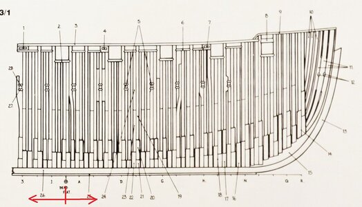
I do not know, if the framing of the kit is prepared with the change of the frame direction - if yes please take care that the direction of the frames is somehwere midships changing - not that you fair the frame(s) towards the wrong direction - so please check this with teh drawings and instruction of the kit

IMG_19331.jpg

This is an excerpt from the Blandford anatomy book, where I marked this mentioned point - yes, the framing of the model is different and simplified compared to Goodwins drawing, but some kits have this
 
Good morning Ken. I really dislike removing char so thanks for this tip if I ever choose a POF model. Looking great and I’m with Paul re the colourful pins and clips ;). Cheers Grant
Thanks Grant, Yes the colourful pins and bands, as this is going to be around on my bench for some time I wanted it to look cheerful, given that it was no extra work it was a no brainier. Ken
 
Hallo Ken - looking very good - also the rubber bands which are bringing really some colour into our boring brown hulls

Small remark:
I do not know, if the framing of the kit is prepared with the change of the frame direction - if yes please take care that the direction of the frames is somehwere midships changing - not that you fair the frame(s) towards the wrong direction - so please check this with teh drawings and instruction of the kit

View attachment 395914

This is an excerpt from the Blandford anatomy book, where I marked this mentioned point - yes, the framing of the model is different and simplified compared to Goodwins drawing, but some kits have this
Thanks for the tip, I’ll look into it, if it doesn’t follow Godwin’s I’ll go with the kit just to keep it simple. Ken
 
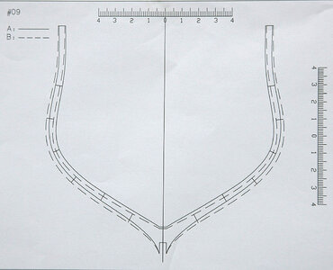
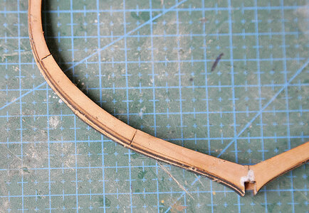
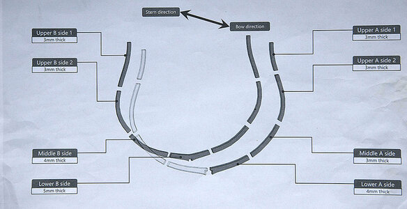
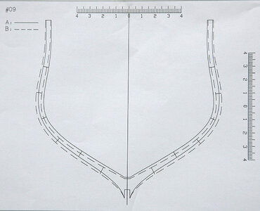
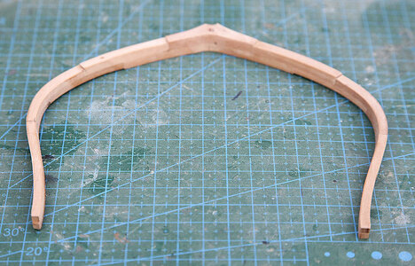
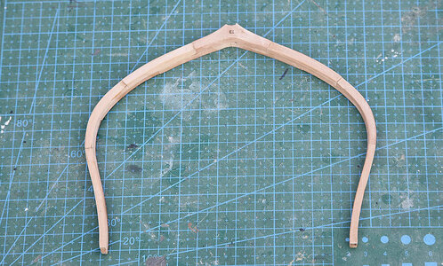
Hello, Again thank you for your encouragements. The rib production line has been going well so far, the ribs up until now have been relatively simple to do as the two layers were place directly on top of each other with no offset. Now I am starting the faired ribs and I’m finding them easy enough to understand but quite tricky to do so things are slowing down a bit, Paul will be happy now. I’ve shown the plan of one such rib, you will see that there are two guides, one a normal line and the other a broken line, you fit the rib pieces that face the stern over the broken line and the forward facing parts over the unbroken guide line this forms an offset rib. Easy enough but there are sanding guides on the parts which show the degree of fairing needed, care is needed to get these guides the correct way round and on the correct sides, whereas before you could place the parts either right or left as they were the same but not so now. At first this looked odd but once I’d done one, sanded it to the guide lines and fitted it into the jig it made a lot more sense.
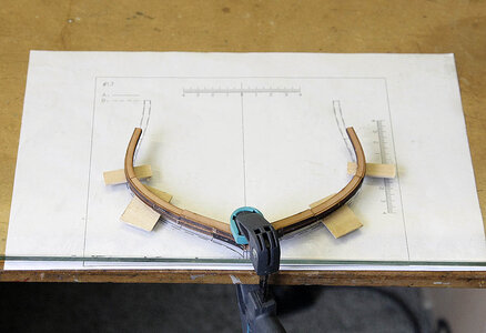
Because of the offset there is less contact area and I found that by just placing it over the plan I couldn’t get an accurate fit easily as the slightest movement when fitting the parts put it out of true, I ended up putting the plan under my glass top and clamping the lower part of the rib over it, just turning it over at each stage, as I moved upwards, I wish that I’d done this earlier as it was so much better and easier to line up accurately.

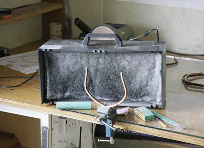
Now when sanding I was not just removing the char but was sanding into the wood so there was a bit more dust being created. As I’d explained I share a study with my wife so to keep her onboard I used a small extractor fan that I’d used as a spray booth placed next to where I sand this helps quite a bit.

066.jpg

064.jpg

067.jpg

068.jpg
 
Last edited:
Woah Ken! The ribs are not off- set. They are placed directly on top of each other as the mid ship frames the solid and dotted lines on the plan just show the position of the edges fore and aft after sanding the fairing
 
Woah Ken! The ribs are not off- set. They are placed directly on top of each other as the mid ship frames the solid and dotted lines on the plan just show the position of the edges fore and aft after sanding the fairing


l hope l caught you in time and my explanation makes sense. Sorry, l hope you have not done too many and they can be rectified
Hi Keith, Yes got it. thanks As I said, I've done a few and they look perfect and fit well. I've shown some pics. I think that on instructions like these they probably often have different interpretations

069.jpg

066.jpg

070.jpg

071.jpg
 
Last edited:
Hi Keith, From how I interpreted the plans and instructions they appear to be offset, this makes sense so that when the ribs are faired they end up being an even thickness across their edge. I can’t think of any other reason that the plan shows this offset. The rib instructions show A as the side facing the bow and B the dotted line facing the stern and the rib guide shows the position of both rib piece A + B and they are different, when fitted they look right, that’s how I saw it.

I think that others might have a look at the rib plan that I’ve shown and perhaps comment. Thanks very much for spotting our different approach and bringing it up.
 
Last edited:
I quietly, frozen, without moving, watch how beauty is born!!
 
Last edited:
The broken and unbroken lines are the positions of the two part frames a and b and therefore mark the maximum and minimum width from bow to stern. The fairing lines have to show the same thing ie the frame is faired once both halves are together. I don't have this kit but if I'm right then the original thickness of the frame parts will match the plan either dotted or undotted. Otherwise it would need be thicker for the fairing to be accommodated.
 
Ken - your previous ship models are superb! The balance of wood colors and your workmanship on the blanking shows
excellent craftsmanship. I'll be following your build - and learning! Best, wayne
 
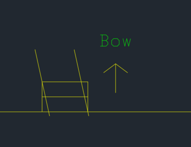
基夫是对的。A和B边一模一样,我就画一个示意图。
从俯视图来看,它应该看起来像这样

Keef is right. Sides A and B are exactly the same, so I will draw a schematic diagram.
From a top view it should look like this

1695413533763.png
 
基夫是对的。A和B边一模一样,我就画一个示意图。
从俯视图来看,它应该看起来像这样

Keefis right. Sides A and B are exactly the same, so I will draw a schematic diagram.
From a top view it should look like this

View attachment 396025
Thanks very much, that makes things much simpler, I've only done a few of the less faired ones and these seem to fit and look ok, it's lucky that this was caught before I got further towards the bow. It highlights what help one can get doing a detailed log. Phew!
 
Last edited:
Back
Top