HMS Diana by Caldercraft

I agree Mustafa, these are all great to have and I feel lucky to have them but none of them are essential. The photo below was built without any of the tools you mentioned as there was no electricity available at the time in England (1775) :)
there were no electric-operated tools, but they used mechanically (foot pedal) operated tools.
 
It is my understanding that there were teams building the models from helpers to apprentices to journeymen. I would love to read more if anyone has any sources about how these old masterpieces were done.
Allan
Hallo Allan and sorry @HMSFly for this short off topic in your log

I just took this book in hand and it is decribing with some information, who were these modelers and also more inormation about the models - maybe you have it in your library, or if not, it is recommended to have......

NAVY BOARD SHIP MODELS, 1650 - 1750
by John Franklin

 
It's unbelievable!
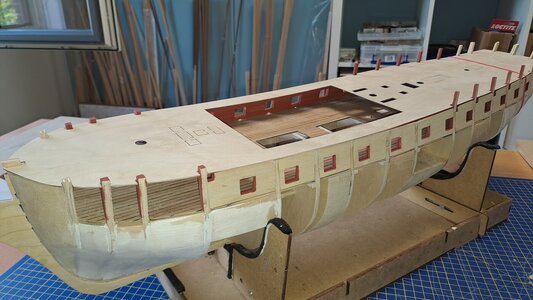
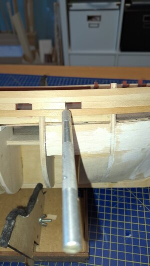
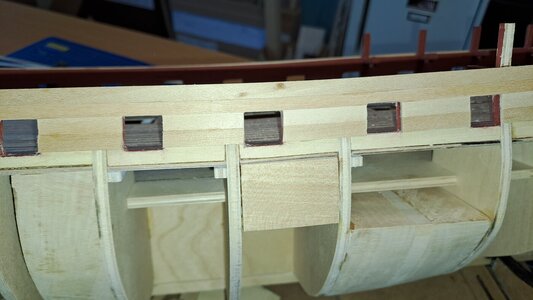
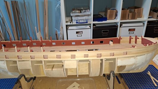
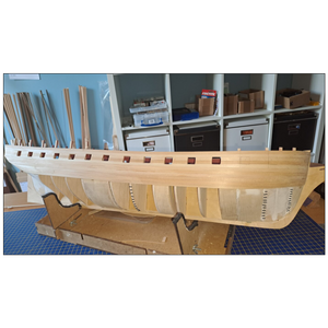
The distance between the Main Deck and the upper part of the Gun Ports is exactly 11 mm: room for a 6 mm strip and one of 5 mm. Precision work that paid off!
As you can see, I also glued 3 strips of 6 mm: 2 x 6 mm between the Gun Ports and the last one fits exactly under the Gun Ports....
I'm verry happy with the result!
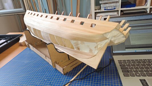
According to plan, two more Gun Ports need to be made in the front part (in the single layer strips). It seems quite fragile to me, so I'm going to apply a second layer of planks on the inside.


Ps:
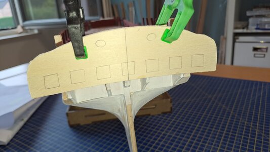
I also made a replica of the Stern to determine the correct placement of the first strips and to check whether the frame of the Stern is correct...

Diana99.jpg

Diana100.jpg

Diana101.jpg

Diana102.jpg

Diana103.jpg
 
You are on a very good way to produce a very good hull planking - very accurate work Thumbsup
 
Before going any further you may find it beneficial to mark out the width of each plank from the dead flat to the stem and to the sternpost. I sketched tick marks on a couple bulkheads in the pic below, in this case 12 strakes to show what I mean. If you have not already tried them tick strips work quickly and easily. Take a strip of scrap paper, and cut one for each bulkhead (or every other one) so it reaches the rabbet to the last plank already on the hull. Then, if there are twelve strakes to add for example, fold each tick strip in half six times then mark the creases and then transfer the marks to the bulkheads. You can then taper the strakes of planking to the width at each point. If it is a tiny bit off on any given bulkhead it is not a problem as you can adjust on the next strake.
Allan
1723595297096.png
 
Last edited:
Before going any further you may find it beneficial to mark out the width of each plank from the dead flat to the stem and to the sternpost. I sketched tick marks on a couple bulkheads in the pic below, in this case 12 strakes to show what I mean. If you have not already tried them tick strips work quickly and easily. Take a strip of scrap paper, and cut one for each bulkhead (or every other one) so it reaches the rabbet to the last plank already on the hull. Then, if there are twelve strakes to add for example, fold each tick strip it in half six times then mark the creases and then transfer the marks to the bulkheads. You can then taper the strakes of planking to the width at each point. If it is a tiny bit off on any given bulkhead it is not a problem as you can adjust on the next strake.
Allan
View attachment 464724
Dear Allan,
Thank you very much for the advice: I'll try it out!

Cheers

Marc
 
Very good planking work Marc.
Is this going to be double planked?
Are some of the planks butt jointed towards the stern. (Sorry I can see they are).
How do you make your bends and tapering?
Bravo
Hey,

Pleas allow me to answer your questions:
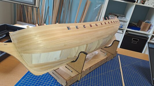
Yes, the Diana is foreseen for double planking. The 2nd layer should be walnut strips of 1.5 x 4 mm.

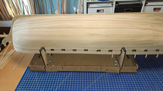
Before I start, I come up with an layout plan. I draw the lines on the Bulkheads with a soft pencil, knowing that there are always deviations...To support the strips, I placed the lime blocks in "strategic" places. With these blocks I create extra space to apply glue and thus provide extra strength to the strips that make bends. Also note that I only use CA (Loctite) glue. This allows me to twist the wood extra in a bend and still glue it immediately... without breaking anything. I also moisten the strips for a maximum of 2 minutes and heat them with a soldering iron, but make sure that the strips are still a little moist... this makes them fold even easier and, as mentioned, with CA glue piece of cake,,,

Photo's: work in progress

Diana110.jpg

Diana111.jpg
 
Hi Marc
Did Fly have a copper bottom? She was launched before it became common practice, but wondered if this was done later in her life.
Allan
 
Hey Allan,

I really don't know if HMS Fly had a copper bottom. I have seen that a sister ship, the HMS Pegasus, was fitted with a copper bottom (Amati construction kit, so I assume this is historically correct?). And there was not a long period between the construction of those 2.
The original plans still exists in the Royal Museums Greenwich.... but I never found this part.

Marc

The HMS Fly got her coppering in 1778 according the information at Dry-docks - so not coppered when she was launched but already two years after - in this period a lot of ships were coppered during a re-fitting

Screenshot 2024-08-15 165102.png

 
Hi Marc,

The information Uwe gives is great. In general copper plating was tried and abandoned early in the 18th century, but then tried again in the late 1770s. Regarding
Pegasus (14) 1776 it probably did not have it when launched and as it sunk 10 months after being launched probably never did. I do not think it is a good idea to trust what any kit proposes without confirming by doing further research first, just as Uwe has done for Fly.


Allan
Perfect! I learned something (again)... ;)
 
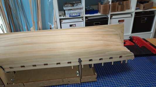
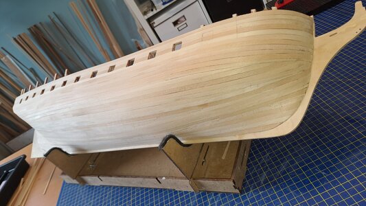
And now the finishing touch: sanding and again sanding....Actually, it doesn't have to be that precise. After all, a second planking is provided with 1x 4 mm Walnutt strips... And then a third layer of copper plates..... A lot off layers....


But, I was very lucky:
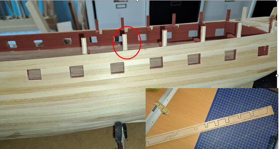
I almost started the 1st planking of the top part of the Bulkheads... But the Bulkheads that stick out have to be sawed off after the "Quarter deck bulkwarks" have been glued to these Bulkheads?????
I'll have to take a closer look at that..... First glue and then saw off... and the Maindeck has cutouts to accommodate the Bulkheads????

Question: How would you solve this issue?

Marc


1723999763511.png

Diana115.jpg

Diana116.jpg

Diana117.jpg
 
But the Bulkheads that stick out have to be sawed off after the "Quarter deck bulkwarks" have been glued to these Bulkheads?????
This makes no sense to me either :( . This following may have nothing to do with their instructions, but just a thought..... The quarter deck bulwark planking is attached to the top timbers which these bulkhead extensions seem to replicate. Why take them off? Then again there may be a good reason. For Diana (38) 1794 these top timbers should be moulded about 5" (in and out thickness) in the range of the quarterdeck (Scantlings of Royal Navy Ships pages 90-91) so maybe you can just sand them down to 2mm (at 1:64) if they are too thick now. The thickness of the spirketting is 3" thick and the quickwork between the spirketting and rail is 2" thick (Scantlings of Royal Navy Ships pages 200-201). The upper works outboard planking (including both layers for a double planked model) for a fifth rate was the depth of the keel divided by 9 (The Construction and Fitting of English Ships of War). In the case of Diana this is 18"/9 = 2 inches (less than 1mm for both outboard planking layers total.) I checked a couple original contracts for fifth rates contemporary to Diana and they give very similar scantlings.

In the end this might be why they recommend removing the bulkhead extensions. To leave them as is, will the total thickness with the planking they supply be too thick? The total thickness with inboard and outboard planking needs to be 9.5" (about 3.75mm) otherwise the sheer rail will be extraordinarily wide.

Allan
 
And now the finishing touch: sanding and again sanding....Actually, it doesn't have to be that precise. After all, a second planking is provided with 1x 4 mm Walnutt strips... And then a third layer of copper plates..... A lot off layers....


But, I was very lucky:
I almost started the 1st planking of the top part of the Bulkheads... But the Bulkheads that stick out have to be sawed off after the "Quarter deck bulkwarks" have been glued to these Bulkheads?????
I'll have to take a closer look at that..... First glue and then saw off... and the Maindeck has cutouts to accommodate the Bulkheads????

Question: How would you solve this issue?

Marc


View attachment 465492

View attachment 465486

View attachment 465487

View attachment 465488
Hi Marc
I'm always amazed at how quickly you build your ships, it's looking very good.
I have no idea about the bulkheads I need to study the plans and instructions before I can comment. Great work as usual
Tony
 
Back
Top