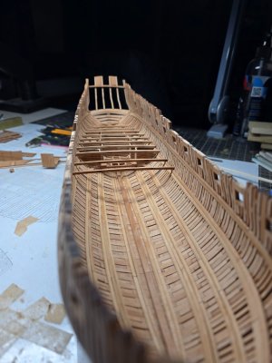
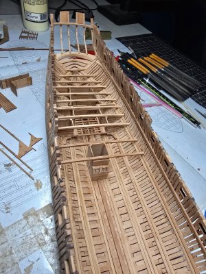
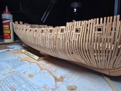
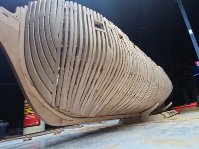
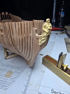
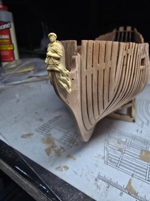
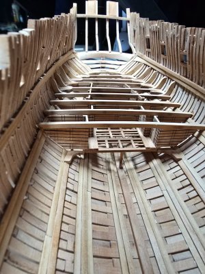
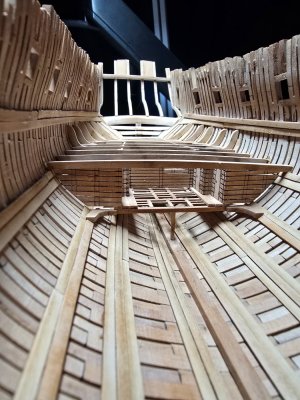
HMS Enterprize 1/96 by Modelship Dockyard

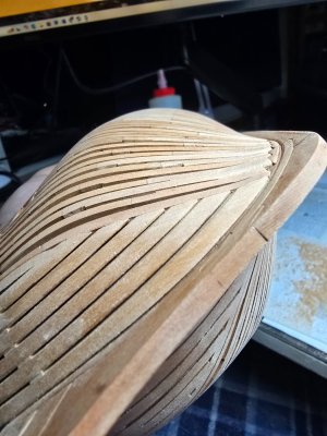
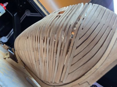
the knee of the head tapers from 11.5" at the stem to 4" at the fore end
I sent a note to the manufacturer and asked about this. They responded they do give instructions in the kit to do this but they did not say if they give the dimensions for the right amount of taper.
Allan
 
Is that pearwood?
Looks great

It is pearwood and it's shaping up nicely.

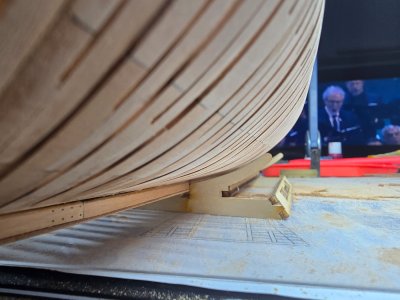
20241118_234319.jpg

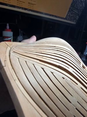
20241118_234402.jpg

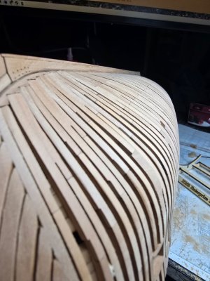
20241118_234445.jpg

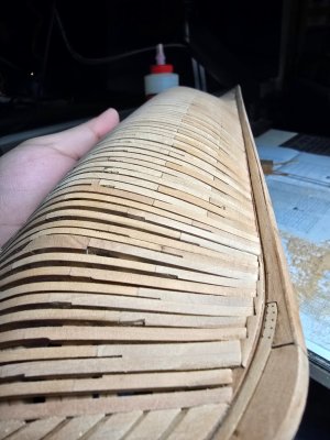
Working with 180 grit to get all the lines smoothed out. Then I'll go back once the shape is right with higher levels of grit to get the smooth finish. As of now you can still see char marks left behind and pencil markings I made early on.
 
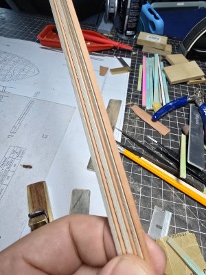
Made some 3mm strips, with the strips being so thin I use a 1/8 basswood board as support, using double sided tape.
20241129_122436.jpg

They come out nearly perfect, with little clean up. Also keeps them safe on the workbench.

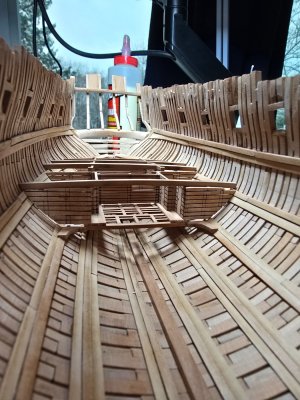
Putting together the read platform not easy.
20241130_163145.jpg
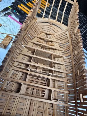
Lot of trial and error, shaping and reshaping of pieces. I missed a lot of photos here, but essentially I built downward. Put together all the cabin walls glued them to the platforms and sanded them until they fit into place.
20241130_231554.jpg

There are probably other ways but I like how it turned out for the most part.
20241130_231542.jpg

20241130_231537.jpg

20241130_235424.jpg

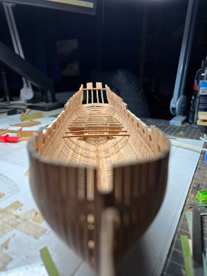
The well isn't glued in place yet, but slowly moving forward. Need to get the mast base in place.

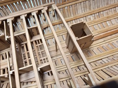
Having an issue with the front platform walls. I have several extra pieces that I don't see where they would fit. But I'm also missing a wall. I have S-8 in place, but there's no second S-8 or same length wall remaining.
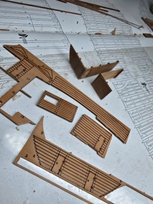
20241130_231741.jpg

So I can either scratch it or leave it without a second wall. We'll see.
 
You just have to trust the process and hope you're earlier builds were in the correct spot. Of the initial set of beams I've only had to remove and relocate one. Another one I just shortened the elbow to fit into place.

20241202_000516.jpg

20241202_000522.jpg

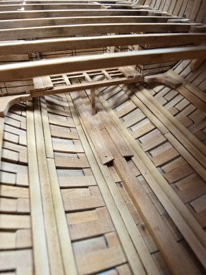
I looked at the next step in the plans several times and for whatever reason I didn't realize that the next step was the building the entire floor of L2, otherwise I wouldn't have glued them in place without all the other pieces in place first. Luckily it worked out.

In the meantime I'm debating whether I want to include ballast.

SmartSelect_20241130_213917_Amazon Shopping.jpg

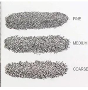
I'm looking at some woodland scenics HO scale ballast, probably course. Wanted to see if anyone had any thoughts, I did a quick search and didn't see other builds with ballast, or at least not using the search terms I used.
 
Good morning. Wow, congratulations. This is superb modeling. Cheers Grant
Thanks!

Okay, looking for thoughts here.

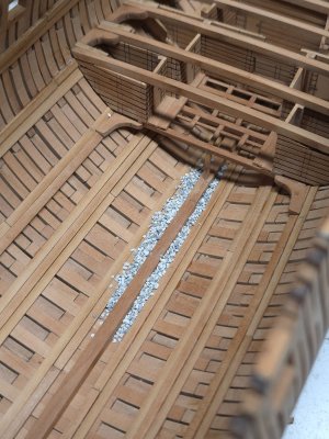
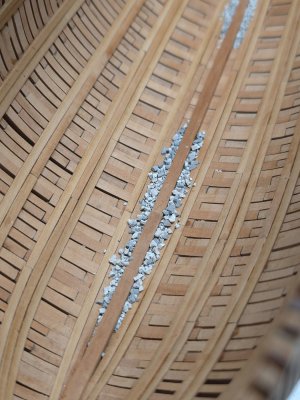
Here is medium by itself.

20241208_202730.jpg

Then medium with large mixed in.

20241208_202725.jpg

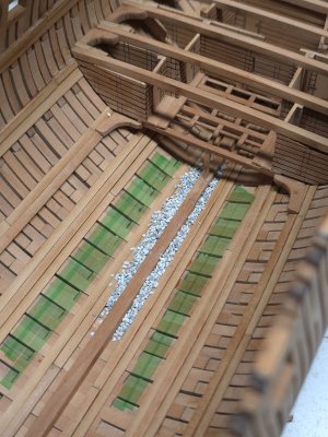
There's also a fine ballast that I will likely mix into which every mix I decide. I think I like how it looks so I think I'll keep the ballast, just a matter of scale. At 1/96 are these the right size
 
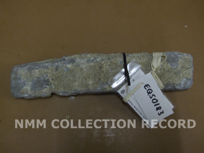
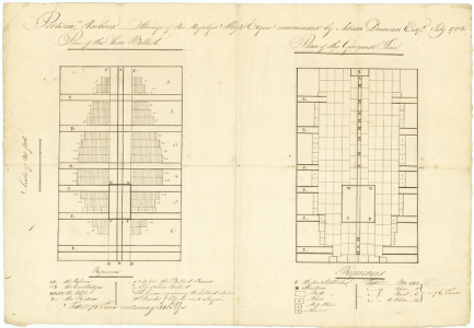
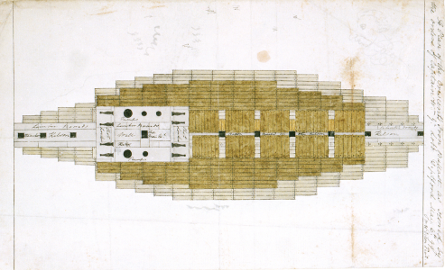
I hope you find the following contemporary drawing on ballasting and barrel storage interesting. Note that the ballast laid on the planking was ingots that were laid to within about 5 inches of the limber boards. There was no ballast next to the keelson. be it shingle as in your photos or pieces of iron. The first photo is a piece of iron ballast (kentledge) circa 1800. These ingots varied in size from about 4"X4" X1' to as large as 6" X6"X3' Shingle was then typically laid on top of the ingots to help secure the barrels. The second post is a typical layout using kentledge on the left and the stowage barrels on the right. The last drawing is a plan of the ballast of the HMS Crescent as stowed by the orders of Captain W. M. Ge Lobb, at Deptford on 6 May 1799.

Allan
1733742390085.png
1733742059984.png
1733742609172.png
 
Last edited:
I hope you find the following contemporary drawing on ballasting and barrel storage interesting. Note that the ballast laid on the planking was ingots that were laid to within about 5 inches of the limber boards. There was no ballast next to the keelson. be it shingle as in your photos or pieces of iron. The first photo is a piece of iron ballast (kentledge) circa 1800. These ingots varied in size from about 4"X4" X1' to as large as 6" X6"X3' Shingle was then typically laid on top of the ingots to help secure the barrels. The second post is a typical layout using kentledge on the left and the stowage barrels on the right. The last drawing is a plan of the ballast of the HMS Crescent as stowed by the orders of Captain W. M. Ge Lobb, at Deptford on 6 May 1799.

Allan
View attachment 489100
View attachment 489099
View attachment 489101

Very helpful again.

So since I have no scale ingots the ballast will have to do. Based on these drawings I believe I'll want to use the small/medium ballast above and keep it in the green highlighted areas.

20241208_202730.jpg

I wasn't planning on doing barrels, but I wonder if I could find some 1/96 barrels
 
So since I have no scale ingots the ballast will have to do. Based on these drawings I believe I'll want to use the small/medium ballast above and keep it in the green highlighted areas.
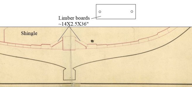
That should work but you can take it down to the limber boards once you install them. On the plan below I drew in shingle only on the left and kentledge and shingle on the right, both of which end at the limber boards. The limber boards rest in place and are loose so they are easy to lift so the ballast should leave them accessible. Hope this is useful.
Allan
1733757821387.jpeg
 
That should work but you can take it down to the limber boards once you install them. On the plan below I drew in shingle only on the left and kentledge and shingle on the right, both of which end at the limber boards. The limber boards rest in place and are loose so they are easy to lift so the ballast should leave them accessible. Hope this is useful.
Allan
View attachment 489148

Those limber boards don't appear to be included in the kit, so I think I'll scratch those. Would those run the entire length of the keel?
 
if I may,Yes along the keel.Frank
Except where the pump tubes and steps were located. :)
Those limber boards don't appear to be included in the kit, so I think I'll scratch those
It is really great to see you go for it and scratch build them as they are so easy to make being no more than a bunch of simple pieces with a couple holes in each end. At 1:96 any scrap less than 1mm thick and 3 or 4mm wide can be used and should look good.

From one contract of 1776:
To prepare Limber Boards of 3 inch Plank of a proper Length, for the more easy taking up, and to do everything in the Hold of the said Ship as shall be necessary, and as usual to a Ship of War.

From a contract in 1702
Limber Boards To be Two Inches and a halfe Thick and One foot Two Inches Broad on Each Side the Kelson.

The Elements and Practice of Naval Archirtecture
gives thicknesses up to 3.5 inches for first rates and the individual pieces were not to exceed three feet in length.
1733777139798.jpeg
Allan
 
Last edited:
Leave the green tape in place and pour some clear acrylic, and Bob’s Your Uncle you”ve got realistic-looking bilgewater ROTF
 
Back
Top