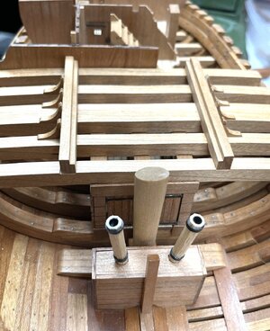
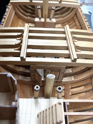
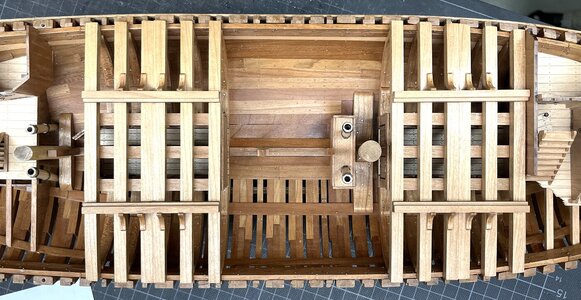
HMS GRANADO - full hull - POF kit by CAF in 1:48 - by Uwe

Anchors and their location

2 * bower anchor with 20 cwt = 1,02 tons - secured all times to the cable - suspended from its cathead and lashed to the side
1 * bower / sheet anchor with 18 cwt = 0,90 tons - free of its cable - lashed abaft starboard bower
1 * stream anchor with 7 1/2 cwt = 0,38 tons - free of its cable - stored under deck
1 * ketch anchor with 3 1/2 cwt = 0,18 tons - free of its cable - lashed to spare bower / sheet anchor
It seems to me it may be impossible to get the Stream anchor below deck. While no dimensions or drawings are given for the Stream anchor, we might assume it is of the same proportions as the Ketch anchor, which is 1.42m x 2.18m x 2.48m. An anchor weighing 7.5 tons will be 1.29 times the size in all dimensions of one weighing 3.5 tons, if sizes and materials are in proportion. Thus the Stream anchor would be about 1.83m x 2.83m x 3.21m. The largest hatch in the deck scales about 2.1m diagonally (2.29m on the model). Putting an anchor this size with its wooden stock attached would be impossible. And difficult if taken apart.

Possibly the Stream anchor would be kept aboard the tender vessel? As might some of its required anchor rope?
 
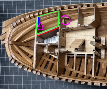
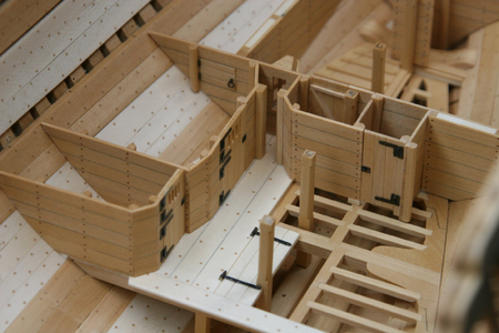
I wonder if the kit is in error when it comes to the After Bulkhead for the Magazine. The kit shows this bulkhead going the whole way across the beam, as you have done here:
1721016544200.png
which creates a small room to the starboard of the Filling Room. However, Goodwin's plan does not show the portion of the wall I've marked in blue above:
1721016225230.png
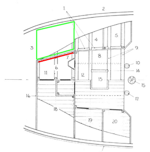
and also gives a name to the area outlined in green above and shaded here as #9:
1721016306723.png
the "Bread Room Annex". This would seem to indicate that the breadroom was more or less an 'L' shape, and that the rear bulkhead of the magazine and filling room did not extend past the port wall of the filling room (drawn in red above).

I already have this bulkhead in place as well, but wonder if it really should be there.

Also, I don't see the small doors included with the kit outlined in purple above on any of Goodwin's drawings. While again, I have included them, I'm not sure what sense it would make to have a door from the Purser's cabin to the Bread Room Annex. Then again, it might make more sense than the floor hatch from the Captain's Day Cabin being the only access to the Breadroom! "Pardon me, Cap, but I've got a mess of hardtack to fetch from the Breadroom to the, uh, mess. Mind movin' yore desk a bit more?"
 
It seems to me it may be impossible to get the Stream anchor below deck. While no dimensions or drawings are given for the Stream anchor, we might assume it is of the same proportions as the Ketch anchor, which is 1.42m x 2.18m x 2.48m. An anchor weighing 7.5 tons will be 1.29 times the size in all dimensions of one weighing 3.5 tons, if sizes and materials are in proportion. Thus the Stream anchor would be about 1.83m x 2.83m x 3.21m. The largest hatch in the deck scales about 2.1m diagonally (2.29m on the model). Putting an anchor this size with its wooden stock attached would be impossible. And difficult if taken apart.

Possibly the Stream anchor would be kept aboard the tender vessel? As might some of its required anchor rope?
Hallo my friend,
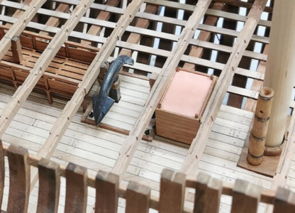
When they stored an anchor under deck the anchor stock was not assembled - in moment I can not find a better photo, but I guess it is understandable

Screenshot 2024-07-16 163324.png

excerpt from the @CAFmodel La Renommee model
 
Last edited:
I wonder if the kit is in error when it comes to the After Bulkhead for the Magazine. The kit shows this bulkhead going the whole way across the beam, as you have done here:
View attachment 459268
which creates a small room to the starboard of the Filling Room. However, Goodwin's plan does not show the portion of the wall I've marked in blue above:
View attachment 459266
and also gives a name to the area outlined in green above and shaded here as #9:
View attachment 459267
the "Bread Room Annex". This would seem to indicate that the breadroom was more or less an 'L' shape, and that the rear bulkhead of the magazine and filling room did not extend past the port wall of the filling room (drawn in red above).

I already have this bulkhead in place as well, but wonder if it really should be there.

Also, I don't see the small doors included with the kit outlined in purple above on any of Goodwin's drawings. While again, I have included them, I'm not sure what sense it would make to have a door from the Purser's cabin to the Bread Room Annex. Then again, it might make more sense than the floor hatch from the Captain's Day Cabin being the only access to the Breadroom! "Pardon me, Cap, but I've got a mess of hardtack to fetch from the Breadroom to the, uh, mess. Mind movin' yore desk a bit more?"
Here it seems, that you are correct
in skecth C4/4 is written under #9 "Bread room wing"
The purser definitely controled the storage of the food, also the bread, so the entrance to the bread room was definitely via the pursor´s cabin, there was no other access, but a door would be more logical
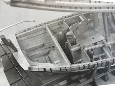
When we take a look at the NMM model we can see this arrangement - too late for my model - Thanks for bringing this up !!! (you can find this photo on page 33
IMG_5467.jpg
 
Here it seems, that you are correct
in skecth C4/4 is written under #9 "Bread room wing"
The purser definitely controled the storage of the food, also the bread, so the entrance to the bread room was definitely via the pursor´s cabin, there was no other access, but a door would be more logical
Yes, although there was the hatch from the Captain's day room. But that never made sense to me.
When we take a look at the NMM model we can see this arrangement - too late for my model - Thanks for bringing this up !!! (you can find this photo on page 33
Ah, yes, thank you, that shows it perfectly. Including the door not shown by Goodman. Now to decide if I want to remove this portion on my model.
 
Here it seems, that you are correct
in skecth C4/4 is written under #9 "Bread room wing"
The purser definitely controled the storage of the food, also the bread, so the entrance to the bread room was definitely via the pursor´s cabin, there was no other access, but a door would be more logical
When we take a look at the NMM model we can see this arrangement - too late for my model - Thanks for bringing this up !!! (you can find this photo on page 33
View attachment 459511
For what its worth...access to the bread room on the Kingfisher was via a small hinged 'door' that someone would have to crawl through... In fact, all the doors on this level would have required ducking, but the one to the bread room was more of a hatch than a door.
 
For what its worth...access to the bread room on the Kingfisher was via a small hinged 'door' that someone would have to crawl through... In fact, all the doors on this level would have required ducking, but the one to the bread room was more of a hatch than a door.
Many thanks for this information - than "my" interpretation is also possible
a small door like I have is the access to the cockies and a second hatch in an additional bulkhead towards the bread .... nobody knows how it was
 
A model kit contains plans, parts, instructions and an abundance of conundrums! :eek:
also kits are interpretations of existing drawings - here the Goodwin Anatomy book
and sometimes Goodwin made mistakes and did not clarify everything
The NMM model was build earlier (in 1975), so in some parts I guess he was in contact with the modeler Lightley during the preparation of his book (1990)

What I want to say, also scratch builder have plans, instructions and an abundance of conundrums!

We are often all in the same boat ;)
 
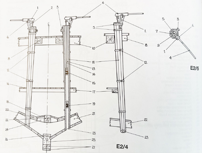
Coming back to the pumps

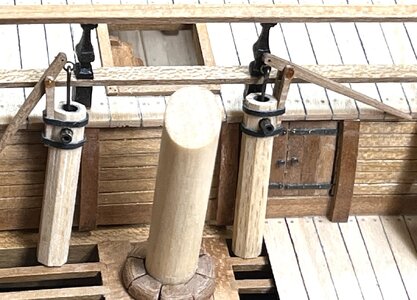
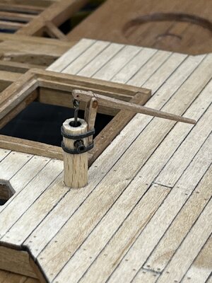
For these two the installation will be not problematic

IMG_5166.jpg

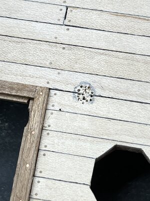
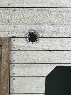
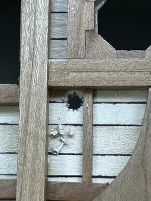
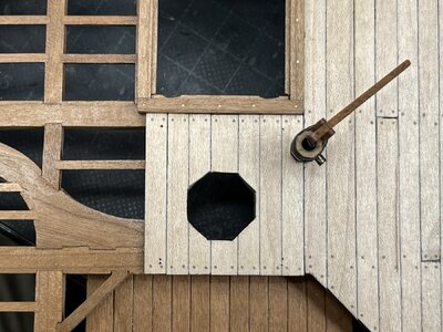
but for one bilge pump I have to cut the deck planking

IMG_5167.jpg

step by step not to make the hole too big

IMG_5169.jpg

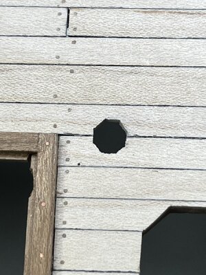
the same location from the undersight

IMG_5168.jpg

IMG_5172.jpg

dryfitted - now only some small black colour missing to immitate the caulking .....

IMG_5170.jpg

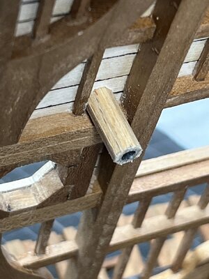
and the view under deck

IMG_5171.jpg

Many Thanks for your interest in my work ..... to be continued ......
 
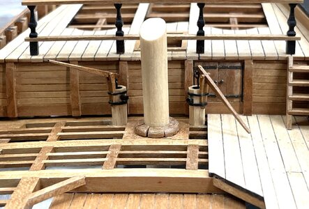
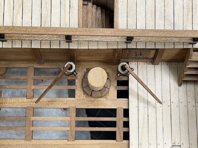
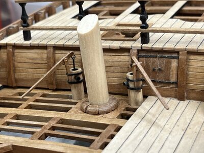
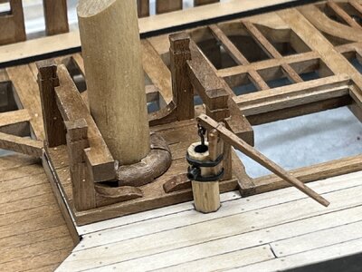
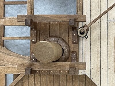
The final look of the elmtree-pumps

according Goodwin the outlets of the firefighting pumps are towards mast

IMG_5239.jpg

IMG_5241.jpg

IMG_5240.jpg

and the outlet of the bilgepumps orianted differently (as normal) - (the second elmtree-pump will be fixed later on, which will be glued only against the deck beam)

IMG_5242.jpg

now also with mast stump etc.

IMG_5243.jpg

IMG_5244.jpg

Many Thanks for your interest - to be continued .....
 
This doesn't make sense, one would try to get the bilge water away from where it's coming from.
It is making sense. because it was not the bilge water (with this pumps)
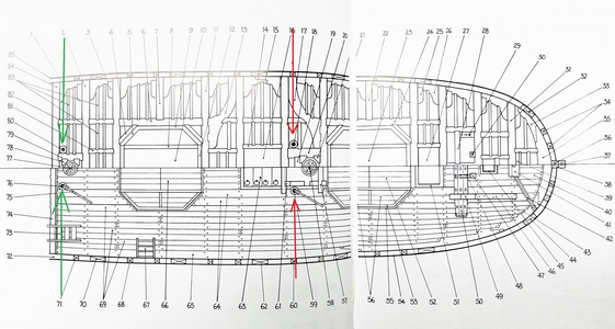
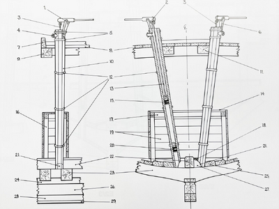
The Granado had altogether four elmtree-pumps - two pairs

1721544653247.png

one pair is next to main mast - the bilge pumps (red arrow)
1721544577874.png

and another pair for domestic and fire fighting - with connection to the seawater through the hull planking (green arrow)
1721544541357.png
 
With the time I am realizing, that some parts are still missing and have to be installed.
These f.e. I recognized in an other building log -> damn, these I have also to install

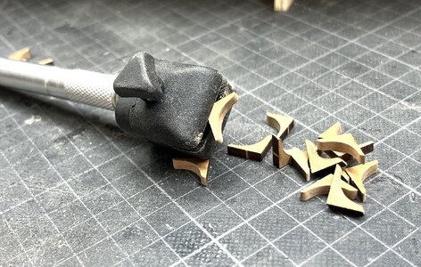
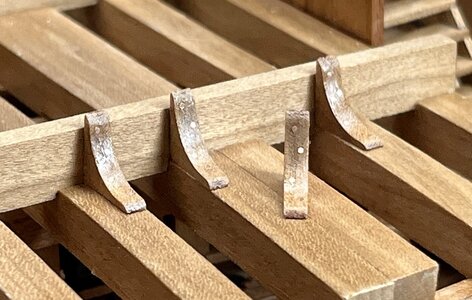
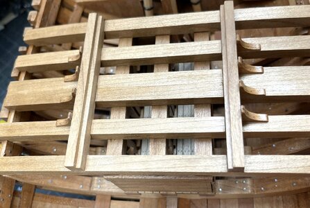
The small knees which are taking over the horizontal forces when the mortar is firing

And I remembered also this small and important small helper to fix small parts during f.e. the laser char removal

IMG_5473.jpg

After char removal I also "installed" copper "bolts"

IMG_5475.jpg

IMG_5474.jpg

IMG_5476.jpg

IMG_5477.jpg

IMG_5479.jpg

IMG_5480.jpg

IMG_5478.jpg

one more small thing installed - some hours of work, nobody will recognize them, but they belong to the Granado
and especially on my "open version" of the Granado they are important

Many Thanks for your interest in my building log ........ to be continued with the rudder assembly
 
Back
Top