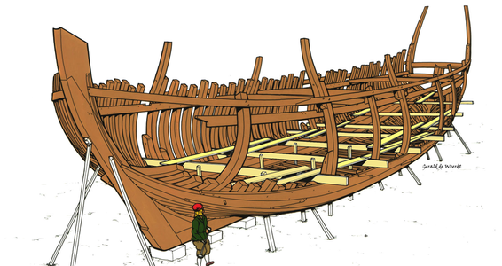
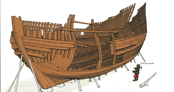
Hohenzollernmodell 1660-1670 Scale 1/75 POF build by Stephan Kertész (Steef66)

Hi Stephan,

Great progress again. What is the size of the planks you are using? By default Ab is mentioning 6 planks in the floor and 3 in the bilge, look like yours are smaller making the task more difficult with more planks.
Guess you are using straight planks? Maybe better to use preshaped planks. Make a template with paper and saw them in shape from thin boards. This creates far less tention in your structure.

Ps I will be joining you soon with the fluyt.
 
Here (Amsterdam 1699) we see 3 templates already in place, before the bottom ist completed. Could be,
that shipwrights sometimes used such devices for forming the shape.

View attachment 368614
If this painting is from 1699 then you can be correct. Shipbuilding in Holland was evolving during this time towards frame first building.
Shell first for large ships was done until the end of the 17th century slowly taken over by frame first.
 
I really do admire your patience and determination Stephan. I freely admit if I was to build shell first, I would cheat and make a timber buck to work aroundROTF

What was the reasoning for the shipwrights to adopt this method of construction as opposed to frame first?

Kind Regards

Nigel
Hi Nigel,

The reason for building like this is that you need less critical expensive pieces of wood. You first build a shell where you can fit in the frame pieces. In the shell you can easily fit the pieces of wood, the length and shape of the pieces are not of the importance as with frame building as these frames pieces are only fitted to the shell and not jointing any other frame parts. This means every internal frame part can have a different size in width and length and thus you have a much better use of the wood available which makes the build lighter and far cheaper then in a frame first ship.
The negative point is that you can t pre design the ship and that the PS and SB side never will be there exact mirror image.
 
Looks really good, real Dutch shipbuilding in miniature. Absolutely impressive.
Thanks Adi for your kind words and visit to my log
wow - hope everything works well or can be adjusted when necessary
amazing work my friend
Thanks Uwe, I can mention with some excitement, however, that it is working out very well so far. I will show it in this update.
Hi Stephan,

I hope to see you and your model during the exhibition in Amsterdam end of September. It is really interesting to follow the dutch method of shipbuilding
Hi Christian, yes I will be there if nothing comes between. Looking forward to meet you there.
This is the construction that has been at the back of my mind

Kind Regards

Nigel
Hi Nigel, like Maarten also explains there are a few construction methods the Dutch used and by the years it evolved. The shell first method is hardly known because other countries don't use this method on their big ships. That's why I wanted to try this method.

Hi Stephan,

Great progress again. What is the size of the planks you are using? By default Ab is mentioning 6 planks in the floor and 3 in the bilge, look like yours are smaller making the task more difficult with more planks.
Guess you are using straight planks? Maybe better to use preshaped planks. Make a template with paper and saw them in shape from thin boards. This creates far less tention in your structure.

Ps I will be joining you soon with the fluyt.
Thanks for your visit Maarten, I use planks that are 2x6 mm. And I think that I end up with7 to 8 planks on the floor and 3 to 4 on the bilge. Don't forget I'm building a 2 decker and not a Pinas. This ship is a little bigger. 6 mm. is in real 450 mm. And that looks to me the size these planks have in real.
The planks are straight and fit them to the ship unshaped. Just adjust the angle I explain later here. After the plank is glued I shape him before I glue the next layer.
The tension in the boards is something to consider, though. And so before I have mounted the floor timbers there may be problems. It is not easy to shape the planks beforehand, because they are not completely flat, which creates weak points in the planks. But by soaking the planks well, you can get the shape reasonably well and after drying you will have a plank that is 80% in shape and has little tension on the glue part.
About time that you start with the fluyt. September is short day.

And everybody I didn't mention thanks for your comments,visit and the likes. I appreciate this.

Now to my update.

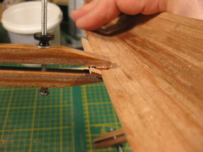
It goes slow, need a lot of measuring before I install a plank. It takes time to dry after soaking in water and when it is dry it takes time to glue. Like I mentioned in the comment to Maarten, I only adjust the angle of the plank before I wet the plank to bend it in shape. I do this on my clamp I got for a long time in my drawer.
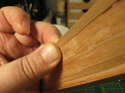
I clamp the plank in it like in the picture.
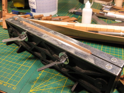
IMG_3465.JPG

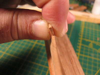
The part that sticks out at the top helps determine the angle. Then I go over it with my plane. I hold the plane in a way that my finger goes allong the side of the clamp. In that way I shape the angle.
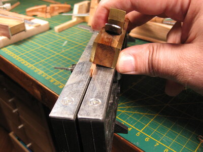
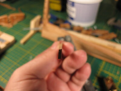
IMG_3467.JPG
IMG_3468.JPG

Then I measure it out on the ship

IMG_3469.JPG
IMG_3470.JPG

Before I wet and bent the plank, I make the joints in it.
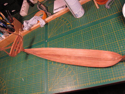
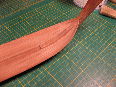
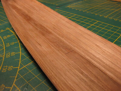
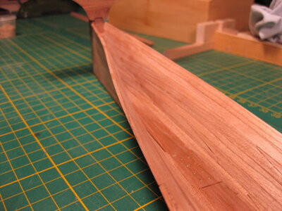
This is the shape of the planking of the bottom at this moment.
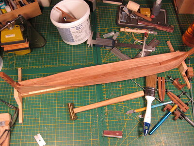
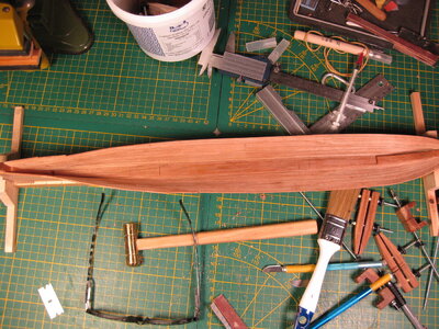
IMG_3471.JPG
IMG_3475.JPG

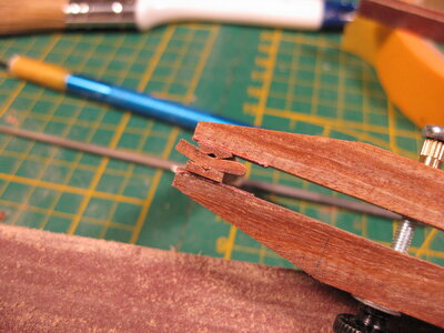
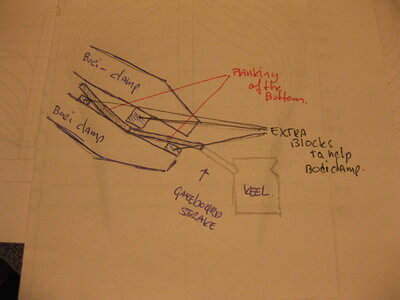
Using the Boei-clamps on planks that are not straight to eachother mounted need some adjustments. Like this drawing I showed before.
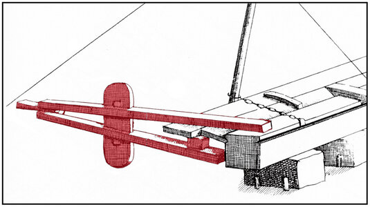
img-6.jpg

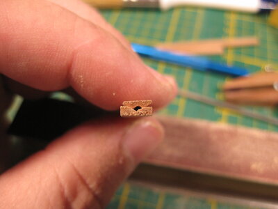
They use a piece of wood to fill up the gap that emerge because of that angle.
Not easy to do on scale, and I still need a way to find out how I handle this problem. I think something like toothpicks to put in between. I find a way and will show it. Because at this moment the angle is getting bigger and need to solve this problem before I can go on.
IMG_3473.JPG

Thanks for the visit
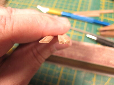
 
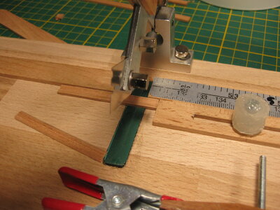
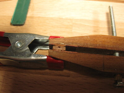
Little update on the clamps. I found a solution. It needed to be something that was 1 part with the clamp. Using pieces of wood that clamp together wouldn't work. Impossible to clamp all these loose pieces together. So I made this and glued them to the clamp. 2 or 3 clamps in this way do the job.

IMG_3477.JPGIMG_3478.JPGIMG_3479.JPGIMG_3480.JPGIMG_3481.JPGIMG_3482.JPG
 
Thanks all for the likes but......
No update because of a redo on the planking :confused: Coffee
After measuring both sides the difference getting more instead of less. So I did a Paula Abdul 1>2<

But the update on the clamps works perfect. Makes the job easier.
 
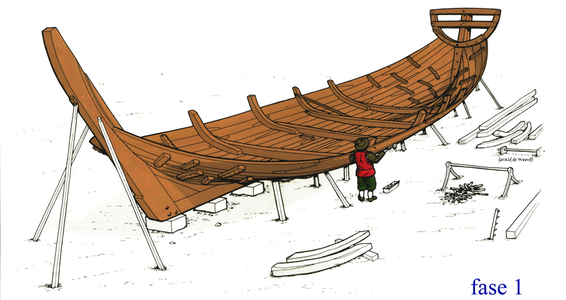
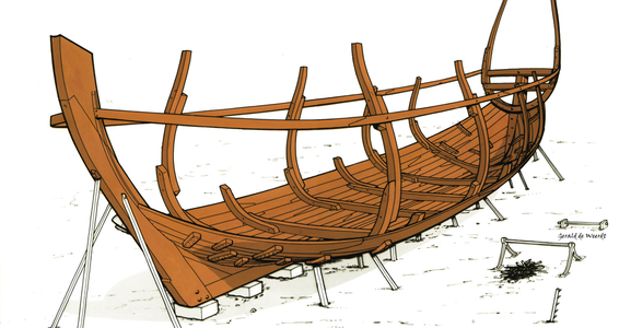
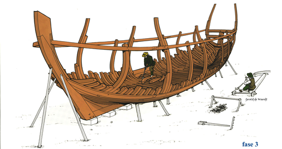
Very impressive Stephan. With regards to the redo - I suppose that is inevitable with this type of build. However, your building method is absolutely correct and seems to follow the WB step by step. If I intrude on your log, I apologize beforehand, but these illustrations give a very good indication of exactly how it worked and supports your theorem perfectly.

Bouw-Barschip-Fase-1.png
bouw-Barschip-Fase-2.png
bouw-Barschip-Fase-3.png
bouw-Barschip-Fase-4.png
Bouw-Barschip-Fase-5.png

Doe zo voort!
 
@all thanks for the likes and
@Heinrich Yes the build is exactly as the illustration you shared with us. Thanks for that. It helps to understand the way it was done. The only thng I don't do is nail the planks together with those tiny blocks on the planking. I use glue. And re-do's are inevitable in this way of building. Clamping wrong or sand to much and it doesn't fit the way it supposed.
But when the re-do comes out in the way you wanted, the joy is great.
I think 1 layer and I can start making the floor timber and futtock bilge.
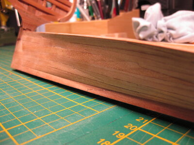
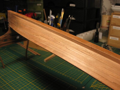
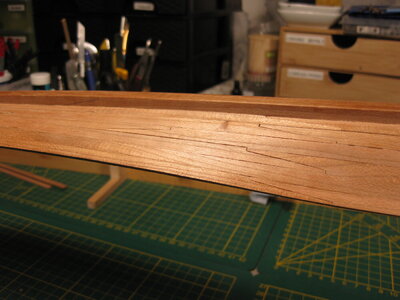
I sand the planks to look nice for the pictures, I need to make here or there tiny corrections by glueing splinters of wood between the planks. Not much but some places need attention.
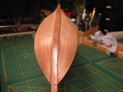
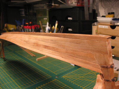
Enjoy the pictures of the state at this moment.

IMG_3483.JPGIMG_3484.JPGIMG_3485.JPGIMG_3486.JPGIMG_3487.JPGIMG_3488.JPGIMG_3489.JPGIMG_3490.JPGIMG_3491.JPGIMG_3492.JPG

Thanks for the visit
 
@all thanks for the likes and
@Heinrich Yes the build is exactly as the illustration you shared with us. Thanks for that. It helps to understand the way it was done. The only thng I don't do is nail the planks together with those tiny blocks on the planking. I use glue. And re-do's are inevitable in this way of building. Clamping wrong or sand to much and it doesn't fit the way it supposed.
But when the re-do comes out in the way you wanted, the joy is great.
I think 1 layer and I can start making the floor timber and futtock bilge.
I sand the planks to look nice for the pictures, I need to make here or there tiny corrections by glueing splinters of wood between the planks. Not much but some places need attention.
Enjoy the pictures of the state at this moment.

View attachment 370426View attachment 370427View attachment 370428View attachment 370429View attachment 370430View attachment 370431View attachment 370432View attachment 370433View attachment 370434View attachment 370435

Thanks for the visit
Wow Stephan. She is showing her nice lines more and more. Great to see the planks with the connection that nicely follows the curve and line.
Regards, Peter
 
Thanks Peter and Paul, kind words

in this picture you could see a repair on one place (green arrow) I glue a thin splinter of wood between the layers and the gap disappear
below (the red arrow) needs to be done.

View attachment 370436
…..and that is all :oops:…… with this extraordinary ‘No Frames To Plank On’ build …….. My respect!
 
…..and that is all :oops:…… with this extraordinary ‘No Frames To Plank On’ build …….. My respect!
on the planks thats all, I think 4 or 5 places. But the biggist issue is in picture number eight of post 288. When you look to the back (stern part) you a big difference on both sides. If I want to carrect that I have to start the hole side again. So I have to live with that. It is like Maarten said to Nigel; "The negative point is that you can t pre design the ship and that the PS and SB side never will be there exact mirror image.".
But thanks for the respect, I think indeed for the first time building like this I did a pretty good job on it, so I do these tiny repairs and leave PS and SB like it is. It gives the ship some character.
 
Hi Stephan,

Did you check the shape of the hull with your lines drawings? Or are you now buikding free form?
It can be due to the pictures but the floor seems to be U shaped.
 
Thanks @shota70 for your kind words. And @all for the likes and visit to my log.
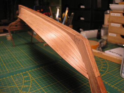
Small update today
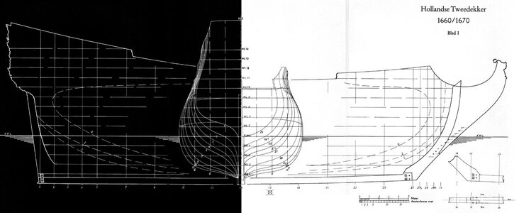
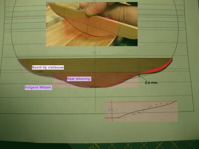
I'm still making layers but also transfer the hull I made to the drawings of the HZ model. Off course there are difference. I did it freehand.
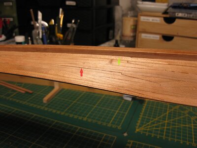
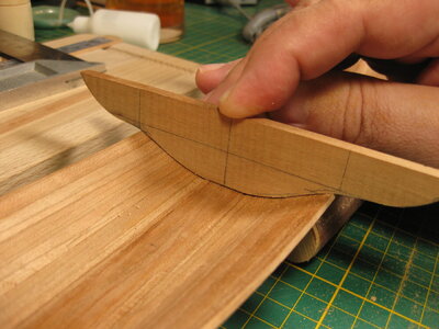
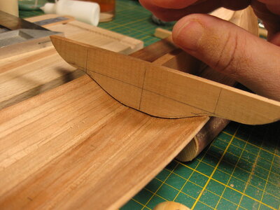
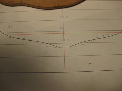
So first to start with the first bulkhead of the drawing. Number 17. I needed to see how much the difference was And I made the start of the first floor timber.
First picture with a little pressure, second without.

IMG_3493.JPG
IMG_3494.JPG

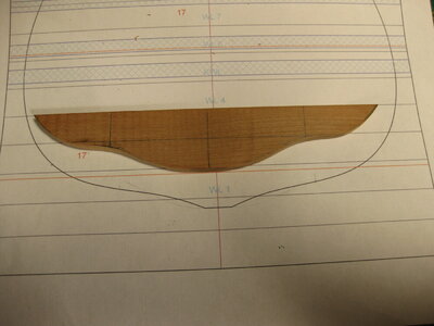
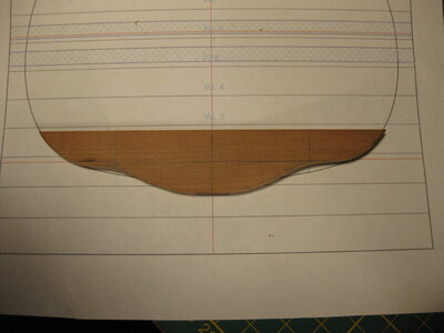
Then I put that piece of wood on the bulkhead on paper.

IMG_3495.JPG
IMG_3496.JPG
IMG_3497.JPG

I am very happy with the results I see, the minimal deviations from the model translated to the drawing delight me. On the stern and on the bow, I did a comparison with the paper templates. And I think I deviate minimally there as well. On the stern I'm almost sure it's right. But real certainty I will get if I do it the way I did with the frame 17. How accurate are these builds. Like Fred Hocker mentioned in @Daniel20 his thread of the Vasa, which is built the same way (at least what I read somewhere): "A key question here is how accurate do you want to be?" If the broad outlines are correct then I am satisfied, it does not have to be accurate to the mm. for me. Who is ever going to measure that?
These ships where actually build without drawings. I use the drawings of the HZ model. Because I want to build a model that looks like that model with al these decorations.

Thanks for watching, more small updates are following. Hope to show you next time the measurements on the bow or stern.
 
On the Dutch forum there where some concerns about the shape of the hull because of the minor anomalies on the surface of the floor.

I think about to adjust the shape on the red part to get rid of the hollow form that seems to appear in the hull
IMG_3496b.jpg

For the hull shape this is not a big problem, it is a small part in the hull that is influence by this. And I think not vissible went corrected in the right way. We see what happened, I have no concerns about it.

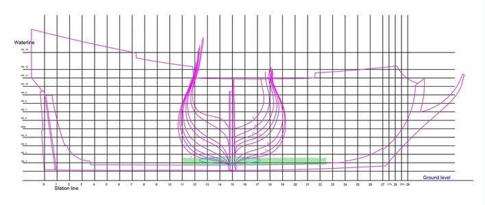
You have to let go of the mindset in this build of I have to follow the drawings exactly. You have to think here more about building a hull that has flowing shapes, no kinks, cavities that are overdone, as well as bulges. Also, you should not expect than starboard and port sides are the same. You are building a Dutchman, there this was not important. I only use the drawings to get the size and whether I am in the right direction since I decided to do shell first. I find a deviation of 1 to 6 mm acceptable depending of course on which point of the ship. Is it very visible or is it actually not noticeable. This deviation is not going to be noticeable considering what part of the ship it is. How small that part is of the entire hull.

Hol2dekontw2.jpg

The green area and the blue circle show the part on the ship.

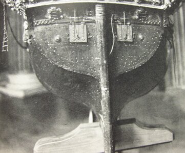
And if you look at the museum model, it appears that its builder wasn't looking too closely either.

IMG_3313.JPG
 
Last edited:
Hi Stephan,

Looking at position 17 I see you are at more or less the centre frame( the "hals" of the hull)
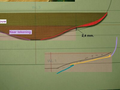
In that case I think your floor is not flat enough. From the keel up the garboard should be at an +/- 45 deg. angle and the following floor planks at ships centre should have a very slight angle creating a more or less flat floor up to the planks at the bilge. I am afraid with your current floor you don t get the hull shape you are aiming for.

I have sketched it below, garboard in blue, floor in yellow and bilge in purple.
IMG_3496b.jpg

If you fill the hull now with floor timbers they will all need a high curvature or a filler piece as you see on English frames. In Dutch ships you don t see this.
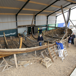
See below the shell of Willem Barentz and you see the floor timbers are nearly straight, even for this jacht with its sleek hull design.
eerste-zitter-1.png
 
Back
Top