Kingfisher 1770 1:48 POF

That’s looking GREAT, Paul. So much to see. I would love to see it in real.
Regards, Paul.
I would LOVE to see many of the models featured on this forum in person!

Just about the best wooden model I have ever seen Paul. Jack
Now you're just being silly Jack. But it's a nice thing to say regardless. My humble thanks...

Absolutely Outstanding. Incredible what you have accomplished.

Jan
Thanks Jan! I'm really having a great time.

Paul, you can be proud, it looks fantastic, great work.
You are very kind, Tobias.

Absolutely fantastic build log and even better model that would grace and improve any museum!! I LOVE the sail room louvers to help dry out the sailcloth and that "hanging" hatch cover!

The open deck really allows one to see the incredible detail and skill of your lower deck structures. You will need to carefully decide how much decking you place, so those details remain visible...tough decisions ahead.

Glad the eye has had NO impact on the results of your build!!! I hope the retina is recovering and the eyesight is slowly restoring itself!!!
Short answer: there won't be much decking. After you spend hour after hour fitting lodging knees and the like it's hard to come up with a reason to cover it all with something boring.

Thanks for asking about my eye. Things have been steadily improving just as the retina specialist promised...until yesterday when there was a small setback...

Another feast for the eye. Great.
Thanks, Stephen. I enjoy your build report as well!
 
Gorgeous model. Is the lower planking done with holly?

I have made top and butt planking for the wales but not below. After seeing yours I will be looking to do this in the future. Peter Goodwin gives a description of this in The Construction and Fitting of the English Man of War that is a bit helpful but if you have other sources with information on this that you can share that would be fantastic.

Many thanks Paul

Allan
Hi Allan,

Yes, I used holly for the lower planking. Generally speaking, I like the color and it is VERY easy to work with - but I found that holly was too soft to make proper treenails to scale. I ended up making these out of boxwood and there is a bit too much contrast. Then again, installing hull trunnels is a serious undertaking so at least you can see my work ROTF.

In the book series The Fully Framed Model, David Antscherl goes into plenty of detail on top/butt planking which was a feature of swan class ships. I wouldn't want to post those pages on the forum but if you PM me... Sadly, Volume 1 (which is the one you would need) is out of print at Seawatch Books.
 
In the book series The Fully Framed Model
Thank you very much Paul. I never thought to look there even though I have used all the TFFM volumes numerous times for other things. I am very lucky to have had David sign each of my copies as each was published. He is truly a master builder and a gentleman.

I love holly for deck planking and planking ships' boats as well. The white lower hull is one reason I will probably not build any warship models when copper plating came into use.

Allan
 
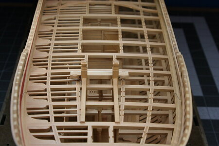
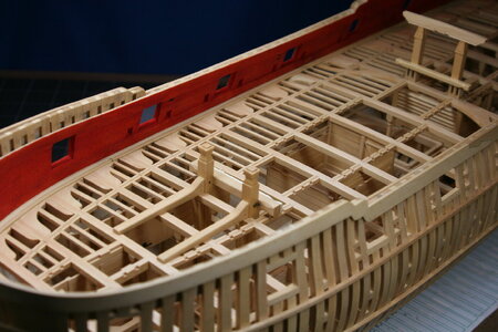
It was a bit of a struggle, but I did manage to install the lower deck structures along with the upper deck framing (sometimes in the reverse order if you can imagine that!). It wasn't elegant, nor free from some (mild) profanity :rolleyes:, but mission accomplished.

But first...the new sail room:

View attachment 458319

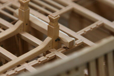
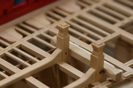
Installing the upper deck pillars:

View attachment 458322

View attachment 458321

Upper deck forward:

View attachment 458324

Upper deck aft:

View attachment 458323

Finally, peaking through the deck to what lies below... Forward:

View attachment 458325

View attachment 458326

The new sail room:

View attachment 458327

Midships (the pumphouse and shot locker):

View attachment 458328

Aft structures:

View attachment 458329

View attachment 458330

Hanging knees (and lodging knees):

View attachment 458331

Next up: upper deck waterways...
Absolutely wonderful, as usual !
 
It was a bit of a struggle, but I did manage to install the lower deck structures along with the upper deck framing (sometimes in the reverse order if you can imagine that!). It wasn't elegant, nor free from some (mild) profanity :rolleyes:, but mission accomplished.

But first...the new sail room:

View attachment 458319

Installing the upper deck pillars:

View attachment 458322

View attachment 458321

Upper deck forward:

View attachment 458324

Upper deck aft:

View attachment 458323

Finally, peaking through the deck to what lies below... Forward:

View attachment 458325

View attachment 458326

The new sail room:

View attachment 458327

Midships (the pumphouse and shot locker):

View attachment 458328

Aft structures:

View attachment 458329

View attachment 458330

Hanging knees (and lodging knees):

View attachment 458331

Next up: upper deck waterways...
As expected this defies description and no language that I possess can convey the joy that viewing such immaculate work brings.

Bravo Paul.
 
Hello friends!

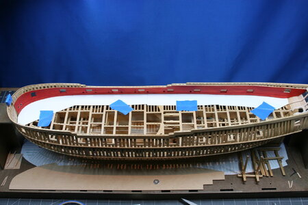
I learned a few things fabricating the waterway on the lower deck that I was able to apply to the (more complex) waterway of the upper deck. First, I discovered a way to make a quick and accurate pattern... In the image below the cardstock (4 overlapping pieces - one for each of the waterway segments) has only been quickly trimmed to approximate the flow of the inner hull:

IMG_0849.JPG

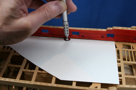
I then used a washer to trace a precise line...

IMG_0848.JPG

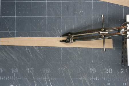
Once I had cut out the cardstock template, I traced that shape onto suitable stock and cut out strips to match. In order to mark the width of the waterway I used a compass:

IMG_0873.JPG

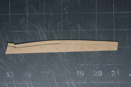
Anyone ever done this???

IMG_0874.JPG

Yes, I am cutting on the wrong side of the line :rolleyes:.

Anyway, I then shaped the waterway to the final profile:

IMG_0878.JPG

Fitted and installed:

IMG_0885.JPG

IMG_0889.JPG

Oh, and somewhere along the way I added this iron knee:

IMG_0887.JPG

On the next post you will see the final installation of the bitts...
 
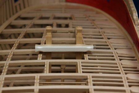
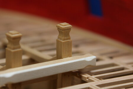
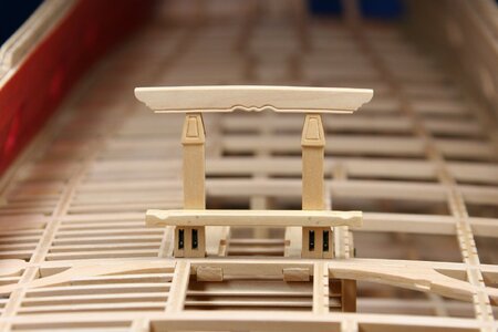
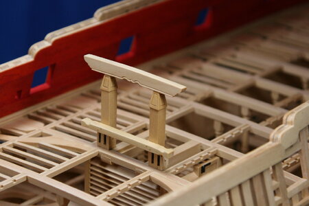
I've actually been moving from the lower deck to the upper deck for nearly three months now. I fabricated the bitts along the way to get a break from walls, doors, beams, carlings, etc... They were shown previously, but have received their final installation.

First, this is the riding bitts (the stove actually sits in between the 'standards' that run on the deck beams):

IMG_0890.JPG

IMG_0891.JPG

IMG_0892.JPG

And a few details:

IMG_0894.JPG

IMG_0895.JPG

IMG_0901.JPG

IMG_0903.JPG

Next, this is the main topsail sheet bitts:

IMG_0896.JPG

IMG_0899.JPG

I have also fabricated the main jeer bitts which sit one beam away from the sheet bitts - but something isn't fitting right so I need to make up some of the quarter deck beams and figure out what is going on.

This build log will go silent now for a few weeks. I'm hanging out the 'gone fishing' sign...

Thanks for stopping by!
 
Hello Friends!

More than a month ago I set out to add the bulkheads and rooms that sit on the aft platform. But as I studied the work progression, I realized that in order to fabricate bulkheads and rooms I needed to first locate the centerline posts that sit under the lower deck beams. But in order to locate the centerline posts I needed to know where the beams would be positioned for the lower deck (at least what I'm calling the lower deck).

Anyway, that's why (seemingly out of nowhere) I fabricated lower deck beams.

With those roughed out I then started working backwards toward the aft platform bulkheads and rooms. And the first job was making the centerline posts:

View attachment 431387 View attachment 431386

I chose to add a bevel to the corners. Here you can see one in position:

View attachment 431388

At this point I realized that the beams (which I had pinned into position) were still moving all over the place. In order to add more stability, I decided that I needed to add the carlings. But in order to do that I needed to cut tabled mortices:

View attachment 431389

View attachment 431390

And now with the carlings in place:

View attachment 431392

Which meant I could FINALLY build a bulkhead.

I started at the back where there is a magazine room (gunpowder and cartridges). You can see this (partial) bulkhead under the most aft beam:

View attachment 431392

View attachment 431393

The bulkheads and walls of the magazine are a complicated affair that are oddly thick and then filled with mortar.

View attachment 431395

View attachment 431394

Everything is just sitting there loose so don't be concerned with fit and finish - that will come later.

Question: is it normal to spend an entire day making a single small bulkhead? Asking for a friend... :rolleyes:
Amazing work... I'm reading your log with great interest and using your work as "gold" reference for a future build. I do have a newbie question thought, since I'm new to wood working in general. How do you actually do the "cut tabled mortices"? they are so precise and finely done. I just have no idea of the instrumentation and/or tools you are using for that. So sorry about the novice question... I'm trying to learn from the master's here.
 
Amazing work... I'm reading your log with great interest and using your work as "gold" reference for a future build. I do have a newbie question thought, since I'm new to wood working in general. How do you actually do the "cut tabled mortices"? they are so precise and finely done. I just have no idea of the instrumentation and/or tools you are using for that. So sorry about the novice question... I'm trying to learn from the master's here.
Hello @Loracs! Welcome to my build report. I have seen three ways to make tabled mortices in beams and carlings for the scratch builder.

1. Chisels - and I mean small chisels (micro chisels). At 1:48 the mortices in the beams (for the carlings) are about 3.6 mm wide and the mortices in the carlings (for the ledges) are around half that (1.8 mm). The first one takes an hour - now I can do them in a couple of minutes.

2. With a table saw! Now you cut the 3.6 mm (or 1.8 mm) dimension by running the beam/carling perpendicular over the blade (top surface facing down) fully notching the piece. You then create the 'table' by scabbing in a 1.5 x1.5 mm piece of wood to create the floor of the mortice. Very simple - and you cannot tell the modeler cheated.

3. With a mill. Now you turn the beam/carling 90 degrees and cut the top of the mortice by moving the piece into the milling head. This creates a perfectly 'squared' notch on the top of the beam/carling. Then, with chisels, you square off the bottom of the mortice to create the table. This is how I have been doing it (unless I am using a kit-supplied part).

Bonus: here is a modelers cheat... Don't even bother to cut the tabled mortice. Using a file (well, maybe some limiting cuts with a #11 XActo blade), file out a 45 degree 'pocket' into the beam/'carling. Now cut a corresponding 45 degree end onto the joining carling/ledge. Again, visually this looks perfect. This is what I do when I have to add a mortice to a beam/carling that is already installed on the model. It is a bit more failsafe and easier to do in situ.

I should mention that all of this depends on rather perfect layout lines. This is where it all goes wrong...
 
Back
Top